2004 SUBARU FORESTER parking brake
[x] Cancel search: parking brakePage 742 of 2870

PM-5
PERIODIC MAINTENANCE SERVICE
Schedule
B: MAINTENANCE SCHEDULE 2
1. EUROPE AREA
Item EveryRepeat short
distance driveRepeat
rough/muddy
road driveExtremely
cold weather
areaSalt or other
corrosive
used or
coastal areaHigh humid-
ity or moun-
tain areaRepeat tow-
ing trailer
Engine oil Replace
more fre-
quentlyReplace
more fre-
quentlyReplace
more fre-
quently
Engine oil filter Replace
more fre-
quentlyReplace
more fre-
quentlyReplace
more fre-
quently
Fuel line 12 months
I 15,000 km
9,000 miles
Transmission oilReplace
more fre-
quently
AT FReplace
more fre-
quently
Front & rear dif-
ferential oilReplace
more fre-
quently
Brake line 12 months
I 15,000 km
9,000 miles
Brake fluid 12 months
R 15,000 km
9,000 miles
Brake pads 12 months
II I I 15,000 km
9,000 miles
Brake linings
and drums12 months
II I I 15,000 km
9,000 miles
Parking brake 12 months
II I I 15,000 km
9,000 miles
Suspension 12 months
III 15,000 km
9,000 miles
Axle boots &
joints12 months
II I I 15,000 km
9,000 miles
Steering system
(Power steering)12 months
III 15,000 km
9,000 miles
Page 743 of 2870

PM-6
PERIODIC MAINTENANCE SERVICE
Schedule
2. EXCEPT FOR EUROPE AREA
Item EveryRepeat short
distance driveRepeat
rough/muddy
road driveExtremely
cold weather
areaSalt or other
corrosive
used or
coastal areaHigh humid-
ity or moun-
tain areaRepeat tow-
ing trailer
Engine oil Replace
more fre-
quentlyReplace
more fre-
quentlyReplace
more fre-
quently
Engine oil filter Replace
more fre-
quentlyReplace
more fre-
quentlyReplace
more fre-
quently
Fuel line 6 months
I 12,500 km
7,500 miles
Transmission oilReplace
more fre-
quently
AT FReplace
more fre-
quently
Front & rear dif-
ferential oilReplace
more fre-
quently
Brake line 6 months
I 12,500 km
7,500 miles
Brake fluid 12 months
R 25,000 km
15,000 miles
Brake pads 6 months
II I I 12,500 km
7,500 miles
Brake linings
and drums6 months
II I I 12,500 km
7,500 miles
Parking brake 6 months
II I I 12,500 km
7,500 miles
Suspension 6 months
III 12,500 km
7,500 miles
Axle boots &
joints6 months
II I I 12,500 km
7,500 miles
Steering system
(Power steering)6 months
III 12,500 km
7,500 miles
Page 771 of 2870

PM-34
PERIODIC MAINTENANCE SERVICE
Brake Linings and Drums
21.Brake Linings and Drums
A: INSPECTION
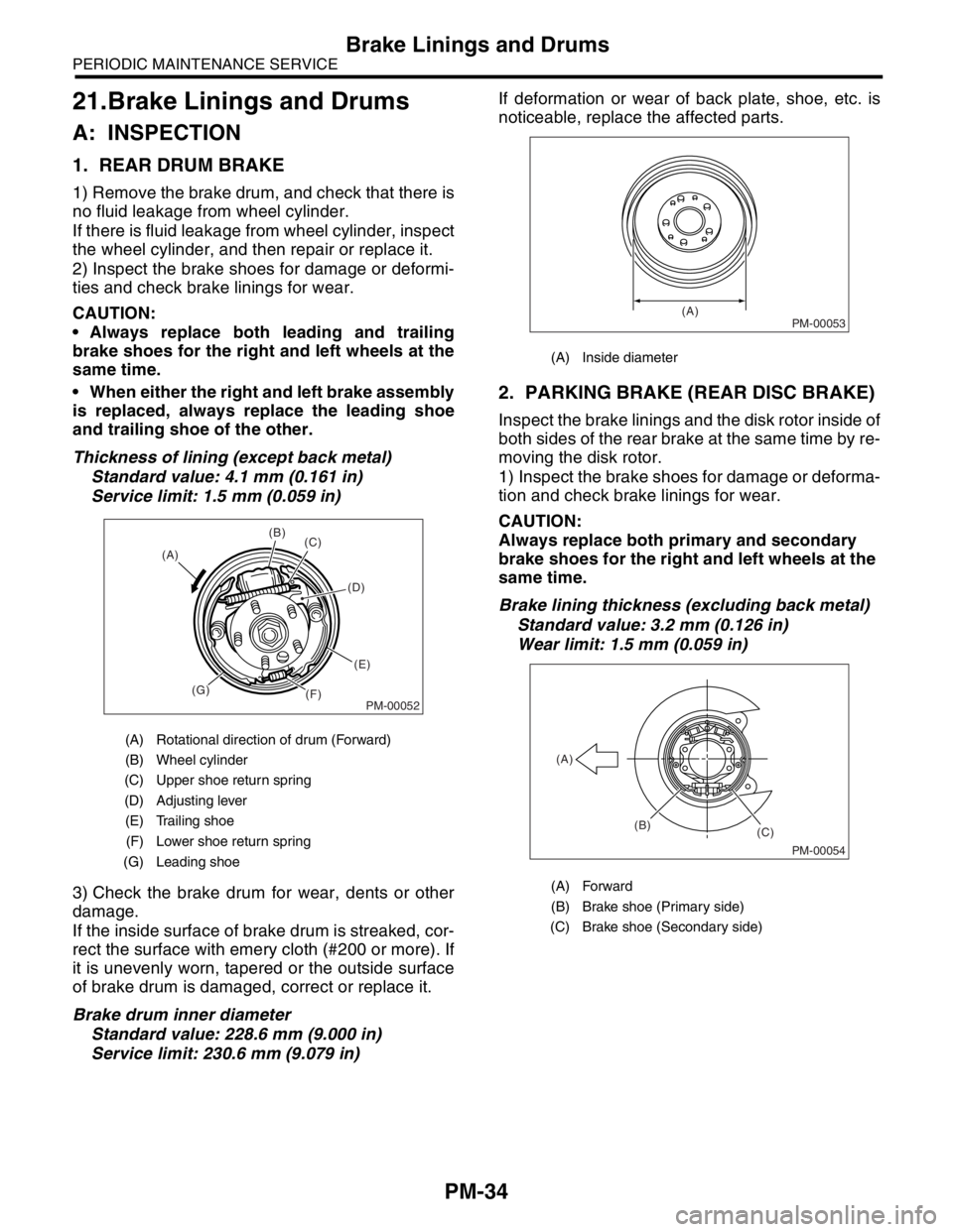
1. REAR DRUM BRAKE
1) Remove the brake drum, and check that there is
no fluid leakage from wheel cylinder.
If there is fluid leakage from wheel cylinder, inspect
the wheel cylinder, and then repair or replace it.
2) Inspect the brake shoes for damage or deformi-
ties and check brake linings for wear.
CAUTION:
Always replace both leading and trailing
brake shoes for the right and left wheels at the
same time.
When either the right and left brake assembly
is replaced, always replace the leading shoe
and trailing shoe of the other.
Thickness of lining (except back metal)
Standard value: 4.1 mm (0.161 in)
Service limit: 1.5 mm (0.059 in)
3) Check the brake drum for wear, dents or other
damage.
If the inside surface of brake drum is streaked, cor-
rect the surface with emery cloth (#200 or more). If
it is unevenly worn, tapered or the outside surface
of brake drum is damaged, correct or replace it.
Brake drum inner diameter
Standard value: 228.6 mm (9.000 in)
Service limit: 230.6 mm (9.079 in)If deformation or wear of back plate, shoe, etc. is
noticeable, replace the affected parts.
2. PARKING BRAKE (REAR DISC BRAKE)
Inspect the brake linings and the disk rotor inside of
both sides of the rear brake at the same time by re-
moving the disk rotor.
1) Inspect the brake shoes for damage or deforma-
tion and check brake linings for wear.
CAUTION:
Always replace both primary and secondary
brake shoes for the right and left wheels at the
same time.
Brake lining thickness (excluding back metal)
Standard value: 3.2 mm (0.126 in)
Wear limit: 1.5 mm (0.059 in)
(A) Rotational direction of drum (Forward)
(B) Wheel cylinder
(C) Upper shoe return spring
(D) Adjusting lever
(E) Trailing shoe
(F) Lower shoe return spring
(G) Leading shoe
PM-00052
(B)
(C)
(D)
(E)
(F) (G) (A)
(A) Inside diameter
(A) Forward
(B) Brake shoe (Primary side)
(C) Brake shoe (Secondary side)
PM-00053(A)
PM-00054
(B)
(C) (A)
Page 772 of 2870

PM-35
PERIODIC MAINTENANCE SERVICE
Brake Linings and Drums
2) Check the disk rotor for wear, dents or other
damage. If the inside surface of disk rotor is
streaked, correct the surface with emery cloth
(#200 or more). If it is unevenly worn or tapered,
correct or replace it.
Brake drum inside diameter
Standard value: 170 mm (6.69 in)
Wear limit: 171 mm (6.73 in)
3) If the deformation or wear of back plate, shoe,
etc. is noticeable, replace them.
4) When the shoe return spring tension is exces-
sively weakened, replace it.B: ADJUSTMENT
1. REAR DRUM BRAKE
The main brake is adjusted automatically, and so
there is no need to adjust it.
2. PARKING BRAKE (REAR DISC BRAKE)
For rear disc brake, adjust the parking brake after
bleeding air.
1) Remove the rear cover (rubber) installed at back
plate.
2) Turn the adjuster toward arrow mark (upward)
until it is locked slightly, by using a flat tip screwdriv-
er as shown in illustration.
3) Turn back (downward) the adjuster 3 to 4 notch-
es.
4) Install the rear cover (rubber) at original position
correctly.
(A) Inside diameter
(B) Disk
PM-00055
(A) (B)
(A) Adjuster
(B) Rear cover (rubber)
(C) Back plate
PM-00056
(B)
(C) (A)
Page 1133 of 2870
![SUBARU FORESTER 2004 Service Repair Manual EN(H4SO)-35
ENGINE (DIAGNOSTIC)
Subaru Select Monitor
8. READ CURRENT DATA FOR AT
1) On the «Main Menu» display screen, select the {Each System Check} and press the [YES] key.
2) On the «System Sel SUBARU FORESTER 2004 Service Repair Manual EN(H4SO)-35
ENGINE (DIAGNOSTIC)
Subaru Select Monitor
8. READ CURRENT DATA FOR AT
1) On the «Main Menu» display screen, select the {Each System Check} and press the [YES] key.
2) On the «System Sel](/manual-img/17/57426/w960_57426-1132.png)
EN(H4SO)-35
ENGINE (DIAGNOSTIC)
Subaru Select Monitor
8. READ CURRENT DATA FOR AT
1) On the «Main Menu» display screen, select the {Each System Check} and press the [YES] key.
2) On the «System Selection Menu» display screen, select the {Transmission} and press the [YES] key.
3) Press the [YES] key after the information of transmission type is displayed.
4) On the «Transmission Diagnosis» display screen, select the {Current Data Display & Save} and press the
[YES] key.
5) On the «Transmission Diagnosis» display screen, select the {Data Display} and press the [YES] key.
6) Using the scroll key, scroll the display screen up or down until the desired data is shown.
A list of the support data is shown in the following table.
Description Display Unit of measure
Battery voltage Battery Voltage V
Rear vehicle speed sensor signal Rear Wheel Speed km/h or MPH
Front vehicle speed sensor signal Front Wheel Speed km/h or MPH
Engine speed signal Engine speed rpm
ATF temperature signal ATF Temp.°C or °F
Throttle position sensor Throttle Sensor Voltage V
Gear Position Gear position —
Line pressure control duty ratio Line pressure duty %
Lock up clutch control duty ratio L/U Duty %
Transfer clutch control duty ratio AWD duty %
Throttle position sensor power supply Throttle sensor power supply V
Turbine revolution signal Turbine Revolution Speed rpm
2-4 Brake timing pressure control duty ratio 2-4 B Pressure Duty %
Intake manifold pressure sensor voltage Mani. Relative Voltage V
FWD switch signal FWD SW ON or OFF
Kick down switch signal Kick Down Switch ON or OFF
Stop light switch signal Stop Light SW ON or OFF
Anti lock brake system signal ABS signal ON or OFF
Cruise control system signal Cruise Control Signal ON or OFF
Neutral/Parking range signal N/P range ON or OFF
Reverse range signal R Range ON or OFF
Drive range signal D Range ON or OFF
3rd range signal 3rd Range Signal ON or OFF
2nd range signal 2nd Range Signal ON or OFF
1st range signal 1st Range Signal ON or OFF
Shift control solenoid A Shift Solenoid #1 ON or OFF
Shift control solenoid B Shift Solenoid #2 ON or OFF
Torque control output signal #1 Torque control output signal 1 ON or OFF
Torque control output signal #2 Torque control output signal 2 ON or OFF
Torque control cut signal Torque Control Cut Sig ON or OFF
2-4 brake timing control solenoid valve 2-4B Timing Solenoid ON or OFF
Low clutch timing control solenoid valve L/C timing solenoid ON or OFF
Automatic transmission diagnosis light output signal Diagnosis Lamp ON or OFF
Page 1137 of 2870

EN(H4SO)-39
ENGINE (DIAGNOSTIC)
Inspection Mode
1. PREPARATION FOR THE INSPECTION
MODE
1) Check battery voltage is more than 12 V and fuel
remains half [20 — 402 (5.3 — 10.6 US gal, 4.4 —
8.8 Imp gal)].
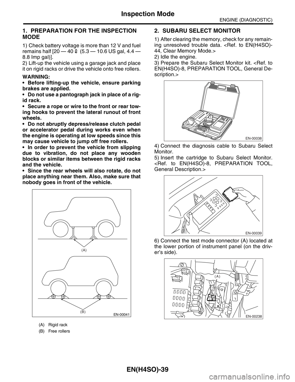
2) Lift-up the vehicle using a garage jack and place
it on rigid racks or drive the vehicle onto free rollers.
WARNING:
Before lifting-up the vehicle, ensure parking
brakes are applied.
Do not use a pantograph jack in place of a rig-
id rack.
Secure a rope or wire to the front or rear tow-
ing hooks to prevent the lateral runout of front
wheels.
Do not abruptly depress/release clutch pedal
or accelerator pedal during works even when
the engine is operating at low speeds since this
may cause vehicle to jump off free rollers.
In order to prevent the vehicle from slipping
due to vibration, do not place any wooden
blocks or similar items between the rigid racks
and the vehicle.
Since the rear wheels will also rotate, do not
place anything near them. Also, make sure that
nobody goes in front of the vehicle.
2. SUBARU SELECT MONITOR
1) After clearing the memory, check for any remain-
ing unresolved trouble data.
2) Idle the engine.
3) Prepare the Subaru Select Monitor kit.
scription.>
4) Connect the diagnosis cable to Subaru Select
Monitor.
5) Insert the cartridge to Subaru Select Monitor.
6) Connect the test mode connector (A) located at
the lower portion of instrument panel (on the driv-
er’s side).
(A) Rigid rack
(B) Free rollers
EN-00041
(A)
(B)
EN-00038
EN-00039
EN-00238
(A)
Page 1138 of 2870

EN(H4SO)-40
ENGINE (DIAGNOSTIC)
Inspection Mode
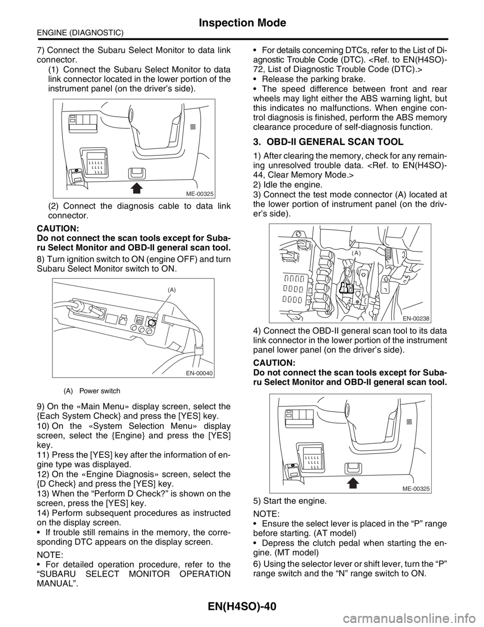
7) Connect the Subaru Select Monitor to data link
connector.
(1) Connect the Subaru Select Monitor to data
link connector located in the lower portion of the
instrument panel (on the driver’s side).
(2) Connect the diagnosis cable to data link
connector.
CAUTION:
Do not connect the scan tools except for Suba-
ru Select Monitor and OBD-II general scan tool.
8) Turn ignition switch to ON (engine OFF) and turn
Subaru Select Monitor switch to ON.
9) On the «Main Menu» display screen, select the
{Each System Check} and press the [YES] key.
10) On the «System Selection Menu» display
screen, select the {Engine} and press the [YES]
key.
11) Press the [YES] key after the information of en-
gine type was displayed.
12) On the «Engine Diagnosis» screen, select the
{D Check} and press the [YES] key.
13) When the “Perform D Check?” is shown on the
screen, press the [YES] key.
14) Perform subsequent procedures as instructed
on the display screen.
If trouble still remains in the memory, the corre-
sponding DTC appears on the display screen.
NOTE:
For detailed operation procedure, refer to the
“SUBARU SELECT MONITOR OPERATION
MANUAL”. For details concerning DTCs, refer to the List of Di-
agnostic Trouble Code (DTC).
Release the parking brake.
The speed difference between front and rear
wheels may light either the ABS warning light, but
this indicates no malfunctions. When engine con-
trol diagnosis is finished, perform the ABS memory
clearance procedure of self-diagnosis function.
3. OBD-II GENERAL SCAN TOOL
1) After clearing the memory, check for any remain-
ing unresolved trouble data.
2) Idle the engine.
3) Connect the test mode connector (A) located at
the lower portion of instrument panel (on the driv-
er’s side).
4) Connect the OBD-II general scan tool to its data
link connector in the lower portion of the instrument
panel lower panel (on the driver’s side).
CAUTION:
Do not connect the scan tools except for Suba-
ru Select Monitor and OBD-II general scan tool.
5) Start the engine.
NOTE:
Ensure the select lever is placed in the “P” range
before starting. (AT model)
Depress the clutch pedal when starting the en-
gine. (MT model)
6) Using the selector lever or shift lever, turn the “P”
range switch and the “N” range switch to ON.
(A) Power switch
ME-00325
EN-00040
(A)
EN-00238
(A)
ME-00325
Page 1139 of 2870

EN(H4SO)-41
ENGINE (DIAGNOSTIC)
Inspection Mode
7) Depress the brake pedal to turn the brake switch
ON. (AT model)
8) Keep the engine speed in the 2,500 — 3,000
rpm range for 40 seconds.
9) Place the select lever or shift lever in the “D”
range (AT model) or “1st” gear (MT model) and
drive the vehicle at 5 to 10 km/h (3 to 6 MPH).
NOTE:
On AWD vehicles, release the parking brake.
The speed difference between front and rear
wheels may light either the ABS warning light, but
this indicates no malfunctions. When engine con-
trol diagnosis is finished, perform the ABS memory
clearance procedure of self-diagnosis system.
10) Using the OBD-II general scan tool, check
DTC(s) and record the result(s).
NOTE:
For detailed operation procedures, refer to the
OBD-II General Scan Tool Operation Manual.
For details concerning DTCs, refer to the List of Di-
agnostic Trouble Code (DTC).