2004 SUBARU FORESTER oil type
[x] Cancel search: oil typePage 921 of 2870

ME(H4SO)-52
MECHANICAL
Timing Belt
2. AUTOMATIC BELT TENSION ADJUST-
ER
1) Visually check oil seals for leaks, and rod ends
for abnormal wear or scratches. If necessary, re-
place faulty parts.
2) Check that the adjuster rod does not move when
a pressure of 294 N (30 kgf, 66 lb) is applied to it.
This is to check adjuster rod stiffness.
3) If the adjuster rod is not stiff and moves freely
when applying 294 N (30 kgf, 66 lb), check it using
the following procedures:
(1) Slowly press the adjuster rod down to the
end surface of the cylinder. Repeat this motion 2
or 3 times.
(2) With the adjuster rod moved all the way up,
apply a pressure of 294 N (30 kgf, 66 lb) to it.
Check adjuster rod stiffness.
(3) If the adjuster rod is not stiff and moves
down, replace the automatic belt tension adjust-
er assembly with a new one.
CAUTION:
Always use a vertical type pressing tool to
move the adjuster rod down.
Do not use a lateral type vise.
Push the adjuster rod vertically.
Press-in the adjuster rod gradually taking
more than 3 minutes.
Do not allow press pressure to exceed 9,807
N (1,000 kgf, 2,205 lb).
Press the adjuster rod as far as the end sur-
face of the cylinder. Do not press the adjuster
rod into the cylinder. Doing so may damage the
cylinder.
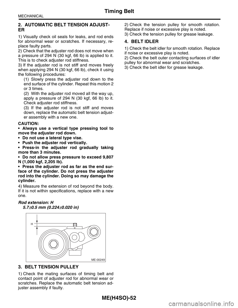
4) Measure the extension of rod beyond the body.
If it is not within specifications, replace with a new
one.
Rod extension: H
5.7
±0.5 mm (0.224±0.020 in)
3. BELT TENSION PULLEY
1) Check the mating surfaces of timing belt and
contact point of adjuster rod for abnormal wear or
scratches. Replace the automatic belt tension ad-
juster assembly if faulty.2) Check the tension pulley for smooth rotation.
Replace if noise or excessive play is noted.
3) Check the tension pulley for grease leakage.
4. BELT IDLER
1) Check the belt idler for smooth rotation. Replace
if noise or excessive play is noted.
2) Check the belt outer contacting surfaces of idler
pulley for abnormal wear and scratches.
3) Check the belt idler for grease leakage.
ME-00249
H
Page 967 of 2870

ME(H4SO)-96
MECHANICAL
Engine Noise
23.Engine Noise
A: INSPECTION
NOTE*:
When disconnecting fuel injector connector, the malfunction indicator light illuminates and DTC is stored in ECM memory.
Therefore, carry out the clear memory mode
Regular clicking soundSound increases as engine
speed increases. Valve mechanism is defective.
Incorrect valve clearance
Worn valve rocker
Worn camshaft
Broken valve spring
Heavy and dull clankOil pressure is low. Worn crankshaft main bearing
Worn connecting rod bearing (big end)
Oil pressure is normal. Loose flywheel mounting bolts
Damaged engine mounting
High-pitched clank (Spark
knock)Sound is noticeable when
accelerating with an overload. Ignition timing advanced
Accumulation of carbon inside combustion chamber
Wrong spark plug
Improper gasoline
Clank when engine speed is
medium (1,000 to 2,000 rpm).Sound is reduced when fuel
injector connector of noisy cyl-
inder is disconnected.
(NOTE*) Worn crankshaft main bearing
Worn bearing at crankshaft end of connecting rod
Knocking sound when engine
is operating under idling speed
and engine is warmSound is reduced when fuel
injector connector of noisy cyl-
inder is disconnected.
(NOTE*) Worn cylinder liner and piston ring
Broken or stuck piston ring
Worn piston pin and hole at piston end of connecting rod
Sound is not reduced if each
fuel injector connector is dis-
connected in turn. (NOTE*) Unusually worn valve lifter
Worn cam gear
Worn camshaft journal bore in crankcase
Squeaky sound — Insufficient generator lubrication
Rubbing sound — Defective generator brush and rotor contact
Gear scream when starting
engine— Defective ignition starter switch
Worn gear and starter pinion
Sound like polishing glass with
a dry cloth— Loose drive belt
Defective water pump shaft
Hissing sound — Loss of compression
Air leakage in air intake system, hoses, connections or mani-
folds
Timing belt noise — Loose timing belt
Belt contacting case/adjacent part
Valve tappet noise — Incorrect valve clearance
Page 985 of 2870

CO(H4SO)-2
COOLING
General Description
1. General Description
A: SPECIFICATION
ModelNon-turbo Turbo
Cooling system Electric fan+Forced engine coolant circulation system
Total engine coolant capacity2(US qt, Imp qt)2.0L with ATF warmer:
Approx. 6.9 (7.29, 6.07)
2.0L AT:
Approx. 6.5 (6.87, 5.72)
2.0L MT:
Approx. 6.6 (6.98, 5.81)
2.5L AT:
Approx. 6.8 (7.19, 5.98)
2.5L MT:
Approx. 6.9 (7.29, 6.07)AT :
Approx. 7.3 (7.71, 6.42)
MT with oil cooler:
Approx. 7.3 (7.71, 6.42)
MT without oil cooler:
Approx. 7.4 (7.82, 6.51)
Water pumpType Centrifugal impeller type
Discharge perfor-
mance IDischarge 202 (5.3 US gal, 4.4 Imp gal)/min.
Pump speed — Discharge
pressure760 rpm — 2.9 kPa (0.3 mAq)
Engine coolant temperature 85°C (185°F)
Discharge perfor-
mance IIDischarge 1002 (26.4 US gal, 22.0 Imp gal)/min.
Pump speed — Discharge
pressure3,000 rpm — 49.0 kPa (5.0 mAq)
Engine coolant temperature 85°C (185°F)
Discharge perfor-
mance IIIDischarge 2002 (52.8 US gal, 44.0 Imp gal)/min.
Pump speed — Discharge
pressure6,000 rpm — 225.4 kPa (23.0 mAq)
Engine coolant temperature 85°C (185°F)
Impeller diameter 76 mm (2.99 in)
Number of impeller vanes 8
Pump pulley diameter 60 mm (2.36 in)
Clearance between
impeller and caseStandard 0.5 — 0.7 mm (0.020 — 0.028 in)
Limit 1.0 mm (0.039 in)
“Thrust” runout of impeller end 0.5 mm (0.020 in)
ThermostatType Wax pellet type
Starts to open 80 — 84°C (176 — 183°F) 76 — 80°C (169 — 176°F)
Fully opened 95°C (203°F) 91°C (196°F)
Valve lift 9.0 mm (0.354 in) or more
Valve bore 35 mm (1.38 in)
Radiator fanMotorMain fan 70 W2.0L AT (K4
★1) : 70 W
2.0L AT (EC, EK★1) :
120 W
2.0 L MT: 70 W
2.5 L: 120 W
Sub fan 70 W2.0L AT (K4
★1) : 70 W
2.0L AT (EC, EK★1) :
120 W
2.0 L MT: 70 W
2.5 L: 120 W
Fan diameter×Blade320 mm (11.81 in)×5 (main fan)
320 mm (11.81 in)×7 (sub fan)
Page 1030 of 2870

LU(H4SO)-2
LUBRICATION
General Description
1. General Description
A: SPECIFICATION
Lubrication methodForced lubrication
Oil pumpPump type Trochoid type
Number of teethInner rotor 9
Outer rotor 10
Outer rotor diameter×thicknessNon-turbo model 78×7 mm (3.07×0.28 in)
Turbo model 78×10 mm (3.07×0.39 in)
Tip clearance between inner and outer rotorStandard 0.04 — 0.14 mm (0.0016 — 0.0055 in)
Limit 0.18 mm (0.0071 in)
Side clearance between inner rotor and pump
caseStandard 0.02 — 0.07 mm (0.0008 — 0.0028 in)
Limit 0.12 mm (0.0047 in)
Case clearance between outer rotor and pump
caseStandard 0.10 — 0.175 mm (0.0039 — 0.0069 in)
Limit 0.20 mm (0.0079 in)
Capacity at
80°C (176°F)Non-turbo
model
600 rpmDischarge
pressure98 kPa (1.0 kg/cm
2, 14 psi)
Discharge
quantity3.22 (3.4 US qt, 2.8 Imp qt)/min.
5,000 rpmDischarge
pressure294 kPa (3.0 kg/cm
2, 43 psi)
Discharge
quantity32.62 (34.4 US qt, 28.7 Imp qt)/min.
Turbo model
600 rpmDischarge
pressure98 kPa (1.0 kg/cm
2, 14 psi)
Discharge
quantity4.62 (4.9 US qt, 4.0 Imp qt)/min.
5,000 rpmDischarge
pressure294 kPa (3.0 kg/cm
2, 43 psi)
Discharge
quantity47.02 (49.7 US qt, 41.4 Imp qt)/min.
Relief valve operation pressureNon-turbo model
490 kPa (5.0 kg/cm
2, 71 psi)
Turbo model
588 kPa (6.0 kg/cm
2, 85 psi)
Oil filterTy p eFull-flow filter type
Filtration areaNon-turbo
760 cm
2 (118 sq in)
Tu r b o
800 cm
2 (124 sq in)
By-pass valve opening pressureNon-turbo
157 kPa (1.60 kg/cm
2, 22.8 psi)
Tu r b o
160 kPa (1.63 kg/cm
2, 23.2 psi)
Outer diameter×widthNon-turbo 80×70 mm (3.15×2.76 in)
Tu r b o 6 8×65 mm (2.68×2.56 in)
Oil filter to engine thread size M 20×1.5
Oil pressure
switchType Immersed contact point type
Working voltage — wattage 12 V — 3.4 W or less
Warning light activation pressure
14.7 kPa (0.15 kg/cm
2, 2.1 psi)
Proof pressure
More than 981 kPa (10 kg/cm
2, 142 psi)
Oil capacity (at replacement) 4.02 (4.2 US qt, 3.5 Imp qt)
Page 1066 of 2870

IG(H4SO)-2
IGNITION
General Description
1. General Description
A: SPECIFICATION
Item Designation
Ignition coil/igni-
tor assemblyModel FH0137
Manufacturer DIAMOND
Primary coil resistance 0.73 Ω±10%
Secondary coil resistance 12.8 kΩ±15%
Insulation resistance between primary terminal and
caseMore than 100 MΩ
Spark plugType and manufacturerCHAMPION: RC10YC4
NGK: BKR5E-11 (Alternate)
Thread size mm 14, P = 1.25
Spark plug gap mm (in) 1.0 — 1.1 (0.039 — 0.043)
Page 1070 of 2870

IG(H4SO)-6
IGNITION
Spark Plug
6) Remove the spark plugs with spark plug sock-
ets.
B: INSTALLATION
1. RH SIDE
Install in the reverse order of removal.
Tightening torque (Spark plug):
21 N
⋅m (2.1 kgf-m, 15.2 ft-lb)
NOTE:
The above torque should be only applied to new
spark plugs without oil on their threads.
In case their threads are lubricated, the torque
should be reduced by approx. 1/3 of the specified
torque in order to avoid over-stressing.
2. LH SIDE
Install in the reverse order of removal.
Tightening torque (Spark plug):
21 N
⋅m (2.1 kgf-m, 15.2 ft-lb)
NOTE:
The above torque should be only applied to new
spark plugs without oil on their threads.
In case their threads are lubricated, the torque
should be reduced by approx. 1/3 of the specified
torque in order to avoid over-stressing.
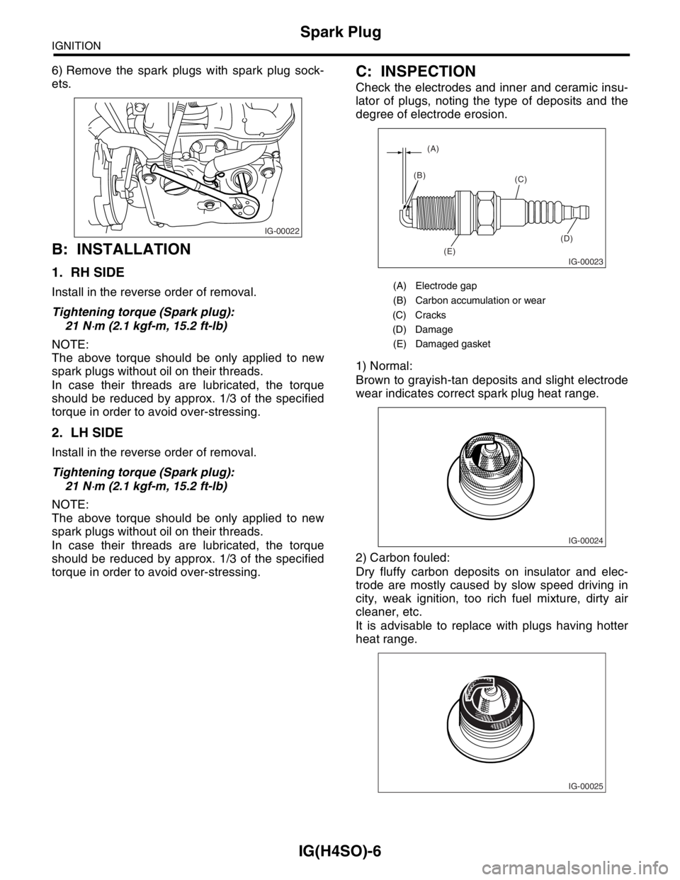
C: INSPECTION
Check the electrodes and inner and ceramic insu-
lator of plugs, noting the type of deposits and the
degree of electrode erosion.
1) Normal:
Brown to grayish-tan deposits and slight electrode
wear indicates correct spark plug heat range.
2) Carbon fouled:
Dry fluffy carbon deposits on insulator and elec-
trode are mostly caused by slow speed driving in
city, weak ignition, too rich fuel mixture, dirty air
cleaner, etc.
It is advisable to replace with plugs having hotter
heat range.
IG-00022
(A) Electrode gap
(B) Carbon accumulation or wear
(C) Cracks
(D) Damage
(E) Damaged gasket
IG-00023
(A)
(B)
(C)
(D)
(E)
IG-00024
IG-00025
Page 1071 of 2870

IG(H4SO)-7
IGNITION
Spark Plug
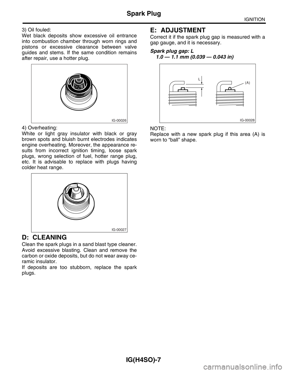
3) Oil fouled:
Wet black deposits show excessive oil entrance
into combustion chamber through worn rings and
pistons or excessive clearance between valve
guides and stems. If the same condition remains
after repair, use a hotter plug.
4) Overheating:
White or light gray insulator with black or gray
brown spots and bluish burnt electrodes indicates
engine overheating. Moreover, the appearance re-
sults from incorrect ignition timing, loose spark
plugs, wrong selection of fuel, hotter range plug,
etc. It is advisable to replace with plugs having
colder heat range.
D: CLEANING
Clean the spark plugs in a sand blast type cleaner.
Avoid excessive blasting. Clean and remove the
carbon or oxide deposits, but do not wear away ce-
ramic insulator.
If deposits are too stubborn, replace the spark
plugs.
E: ADJUSTMENT
Correct it if the spark plug gap is measured with a
gap gauge, and it is necessary.
Spark plug gap: L
1.0 — 1.1 mm (0.039 — 0.043 in)
NOTE:
Replace with a new spark plug if this area (A) is
worn to “ball” shape.
IG-00026
IG-00027
IG-00028
L
(A)
Page 1503 of 2870

ME(H4DOTC)-45
MECHANICAL
Engine Assembly
26) Support the transmission with a garage jack.
NOTE:
Before moving the engine away from transmission,
check to be sure no work has been overlooked. Do-
ing this is very important in order to facilitate re-in-
stallation and because transmission lowers under
its own weight.
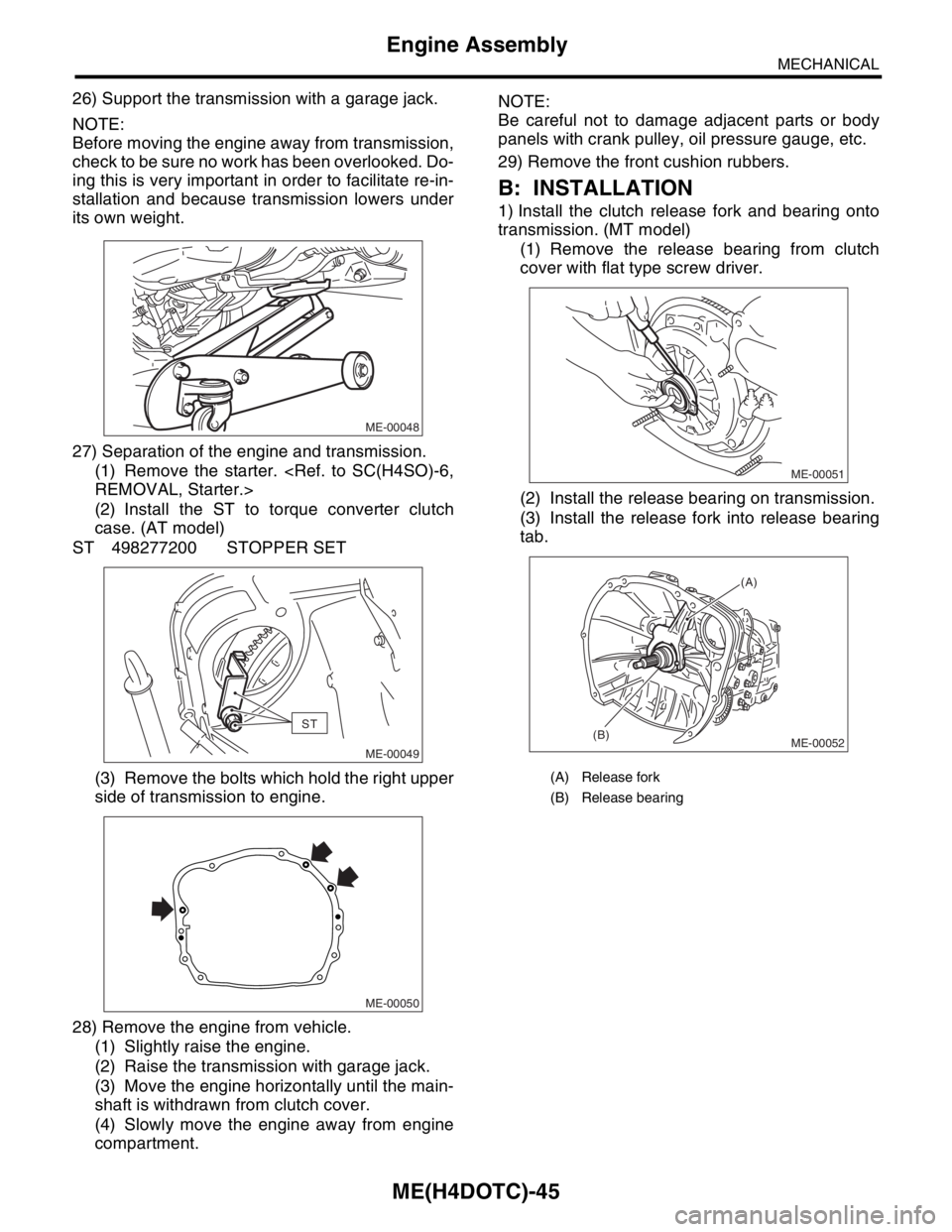
27) Separation of the engine and transmission.
(1) Remove the starter.
(2) Install the ST to torque converter clutch
case. (AT model)
ST 498277200 STOPPER SET
(3) Remove the bolts which hold the right upper
side of transmission to engine.
28) Remove the engine from vehicle.
(1) Slightly raise the engine.
(2) Raise the transmission with garage jack.
(3) Move the engine horizontally until the main-
shaft is withdrawn from clutch cover.
(4) Slowly move the engine away from engine
compartment.NOTE:
Be careful not to damage adjacent parts or body
panels with crank pulley, oil pressure gauge, etc.
29) Remove the front cushion rubbers.
B: INSTALLATION
1) Install the clutch release fork and bearing onto
transmission. (MT model)
(1) Remove the release bearing from clutch
cover with flat type screw driver.
(2) Install the release bearing on transmission.
(3) Install the release fork into release bearing
tab.
ME-00048
ST
ME-00049
ME-00050
(A) Release fork
(B) Release bearing
ME-00051
ME-00052
(A)
(B)