2004 SUBARU FORESTER engine
[x] Cancel search: enginePage 2743 of 2870
5MT-31
MANUAL TRANSMISSION AND DIFFERENTIAL
Transmission Gear Oil
2. Transmission Gear Oil
A: INSPECTION
1) Park the vehicle on a level surface.
2) Turn the ignition switch to OFF, and wait until the
engine cools.
3) Remove the oil level gauge and wipe it clean.
4) Reinsert the level gauge all the way. Be sure that
the level gauge is correctly inserted and in the
proper direction.
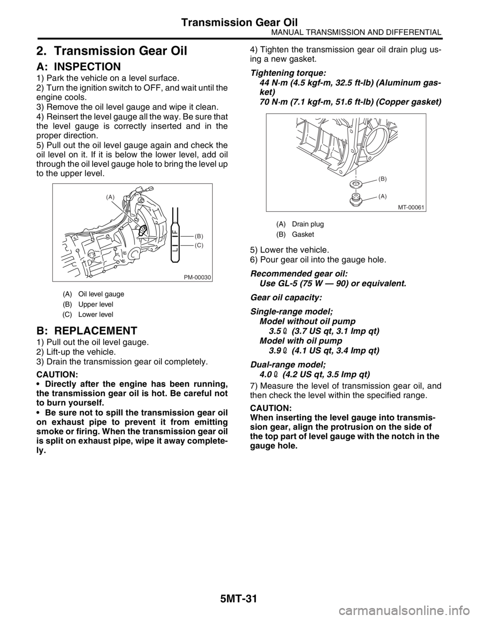
5) Pull out the oil level gauge again and check the
oil level on it. If it is below the lower level, add oil
through the oil level gauge hole to bring the level up
to the upper level.
B: REPLACEMENT
1) Pull out the oil level gauge.
2) Lift-up the vehicle.
3) Drain the transmission gear oil completely.
CAUTION:
Directly after the engine has been running,
the transmission gear oil is hot. Be careful not
to burn yourself.
Be sure not to spill the transmission gear oil
on exhaust pipe to prevent it from emitting
smoke or firing. When the transmission gear oil
is split on exhaust pipe, wipe it away complete-
ly.4) Tighten the transmission gear oil drain plug us-
ing a new gasket.
Tightening torque:
44 N·m (4.5 kgf-m, 32.5 ft-lb) (Aluminum gas-
ket)
70 N·m (7.1 kgf-m, 51.6 ft-lb) (Copper gasket)
5) Lower the vehicle.
6) Pour gear oil into the gauge hole.
Recommended gear oil:
Use GL-5 (75 W — 90) or equivalent.
Gear oil capacity:
Single-range model;
Model without oil pump
3.52 (3.7 US qt, 3.1 Imp qt)
Model with oil pump
3.92 (4.1 US qt, 3.4 Imp qt)
Dual-range model;
4.02 (4.2 US qt, 3.5 Imp qt)
7) Measure the level of transmission gear oil, and
then check the level within the specified range.
CAUTION:
When inserting the level gauge into transmis-
sion gear, align the protrusion on the side of
the top part of level gauge with the notch in the
gauge hole.
(A) Oil level gauge
(B) Upper level
(C) Lower level
PM-00030
(B)
(C) (A)
(A) Drain plug
(B) Gasket
MT-00061
(A) (B)
Page 2745 of 2870
5MT-33
MANUAL TRANSMISSION AND DIFFERENTIAL
Manual Transmission Assembly
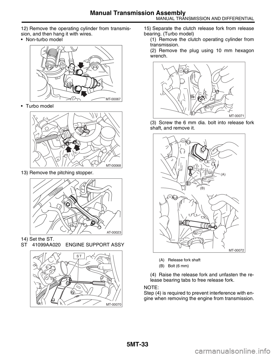
12) Remove the operating cylinder from transmis-
sion, and then hang it with wires.
Non-turbo model
Turbo model
13) Remove the pitching stopper.
14) Set the ST.
ST 41099AA020 ENGINE SUPPORT ASSY15) Separate the clutch release fork from release
bearing. (Turbo model)
(1) Remove the clutch operating cylinder from
transmission.
(2) Remove the plug using 10 mm hexagon
wrench.
(3) Screw the 6 mm dia. bolt into release fork
shaft, and remove it.
(4) Raise the release fork and unfasten the re-
lease bearing tabs to free release fork.
NOTE:
Step (4) is required to prevent interference with en-
gine when removing the engine from transmission.
MT-00067
MT-00068
AT-00023
MT-00070
ST(A) Release fork shaft
(B) Bolt (6 mm)
MT-00071
MT-00072 (B)(A)
Page 2746 of 2870
5MT-34
MANUAL TRANSMISSION AND DIFFERENTIAL
Manual Transmission Assembly
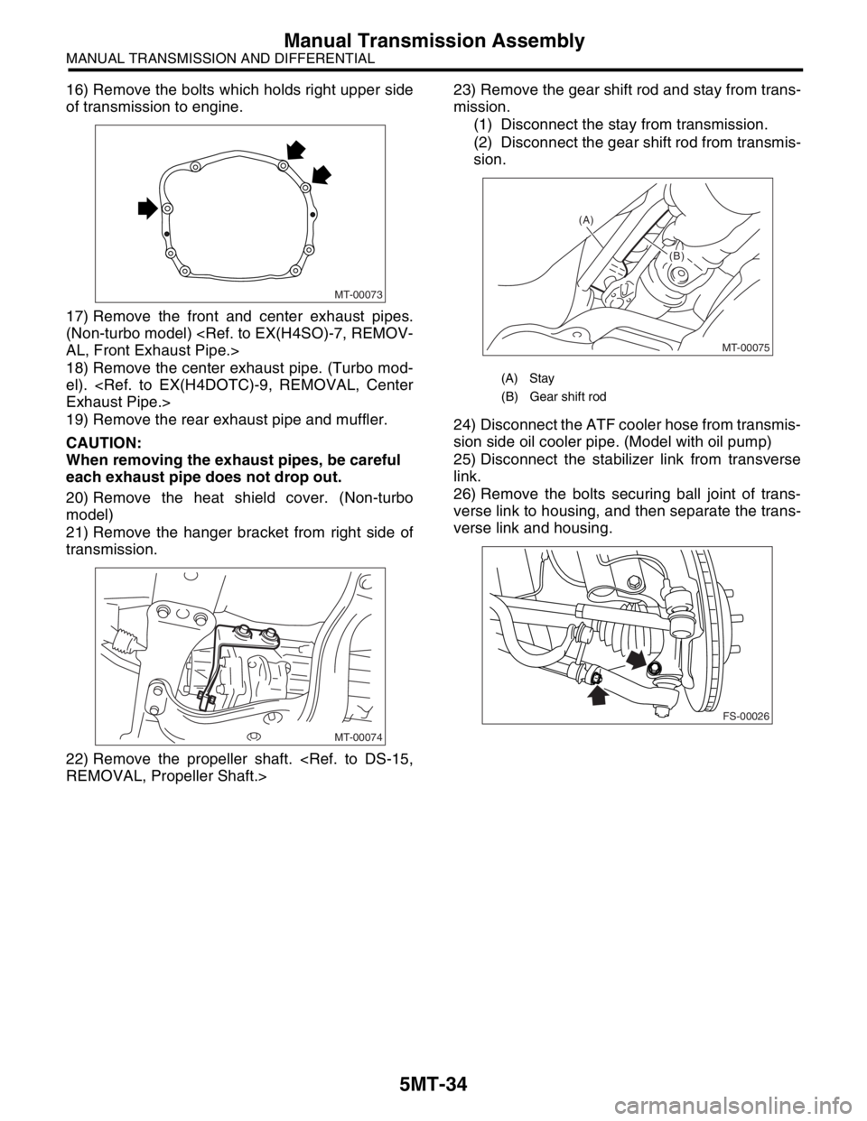
16) Remove the bolts which holds right upper side
of transmission to engine.
17) Remove the front and center exhaust pipes.
(Non-turbo model)
18) Remove the center exhaust pipe. (Turbo mod-
el).
19) Remove the rear exhaust pipe and muffler.
CAUTION:
When removing the exhaust pipes, be careful
each exhaust pipe does not drop out.
20) Remove the heat shield cover. (Non-turbo
model)
21) Remove the hanger bracket from right side of
transmission.
22) Remove the propeller shaft.
mission.
(1) Disconnect the stay from transmission.
(2) Disconnect the gear shift rod from transmis-
sion.
24) Disconnect the ATF cooler hose from transmis-
sion side oil cooler pipe. (Model with oil pump)
25) Disconnect the stabilizer link from transverse
link.
26) Remove the bolts securing ball joint of trans-
verse link to housing, and then separate the trans-
verse link and housing.
MT-00073
MT-00074
(A) Stay
(B) Gear shift rod
MT-00075
(A)
(B)
(B)
FS-00026
Page 2747 of 2870
5MT-35
MANUAL TRANSMISSION AND DIFFERENTIAL
Manual Transmission Assembly
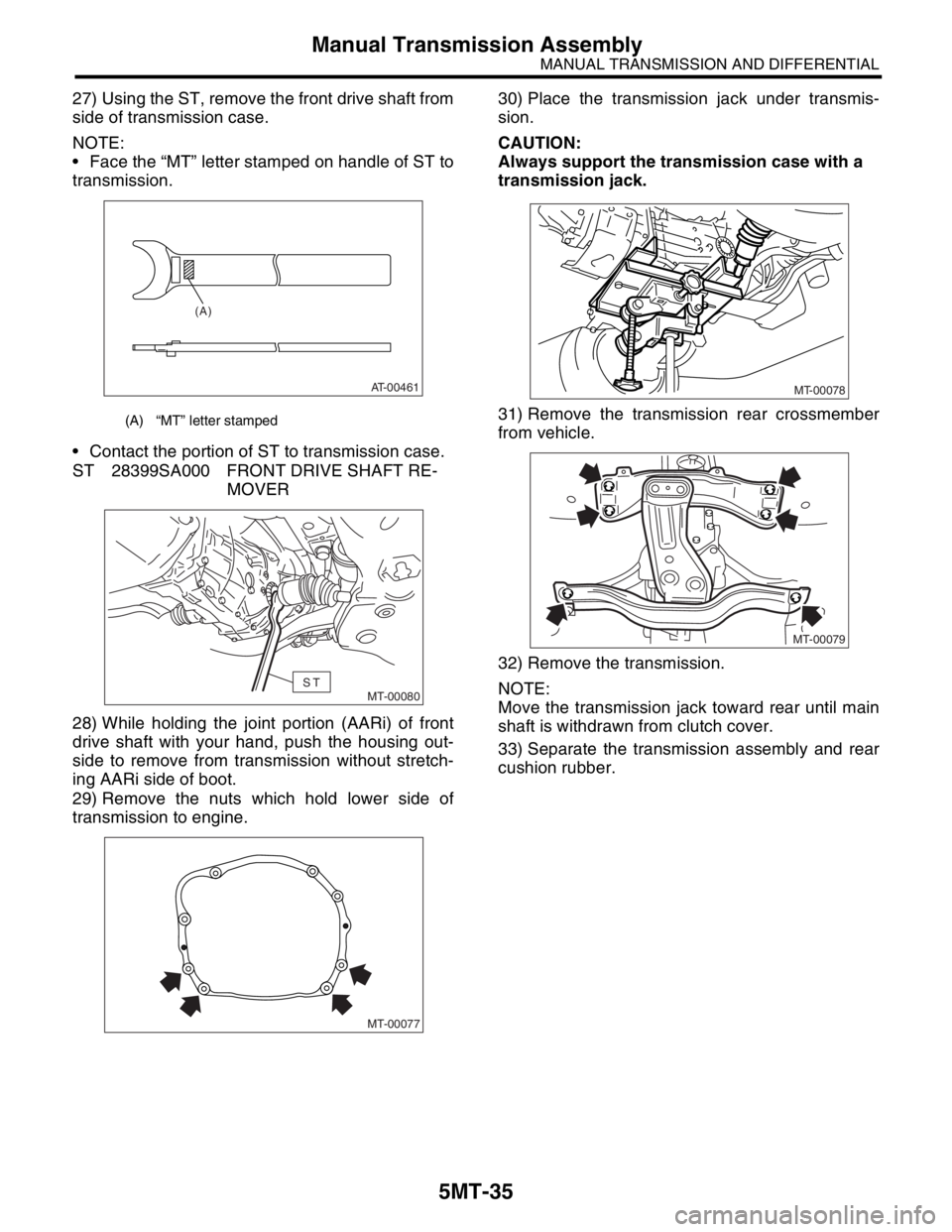
27) Using the ST, remove the front drive shaft from
side of transmission case.
NOTE:
Face the “MT” letter stamped on handle of ST to
transmission.
Contact the portion of ST to transmission case.
ST 28399SA000 FRONT DRIVE SHAFT RE-
MOVER
28) While holding the joint portion (AARi) of front
drive shaft with your hand, push the housing out-
side to remove from transmission without stretch-
ing AARi side of boot.
29) Remove the nuts which hold lower side of
transmission to engine.30) Place the transmission jack under transmis-
sion.
CAUTION:
Always support the transmission case with a
transmission jack.
31) Remove the transmission rear crossmember
from vehicle.
32) Remove the transmission.
NOTE:
Move the transmission jack toward rear until main
shaft is withdrawn from clutch cover.
33) Separate the transmission assembly and rear
cushion rubber.
(A) “MT” letter stamped
AT-00461
(A)
MT-00080ST
MT-00077
MT-00078
MT-00079
Page 2748 of 2870
5MT-36
MANUAL TRANSMISSION AND DIFFERENTIAL
Manual Transmission Assembly
B: INSTALLATION
1) Replace the differential side retainer oil seal with
a new one.
NOTE:
When pulling out the front drive shaft, always re-
place the differential side retainer oil seal.
2) Install the rear cushion rubber to transmission
assembly.
Tightening torque:
35 N·m (3.57 kgf-m, 25.8 ft-lb)
3) Install the clutch release lever and bearing onto
transmission. (Turbo model)
4) Install the transmission onto engine.
(1) Gradually raise the transmission with trans-
mission jack.
(2) Engage them at splines.
NOTE:
Be careful not to strike the main shaft against clutch
cover.
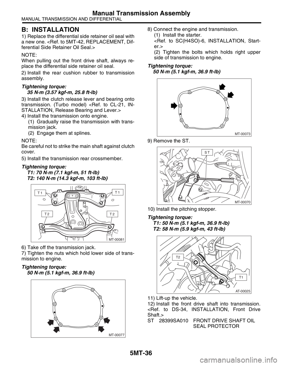
5) Install the transmission rear crossmember.
Tightening torque:
T1: 70 N·m (7.1 kgf-m, 51 ft-lb)
T2: 140 N·m (14.3 kgf-m, 103 ft-lb)
6) Take off the transmission jack.
7) Tighten the nuts which hold lower side of trans-
mission to engine.
Tightening torque:
50 N·m (5.1 kgf-m, 36.9 ft-lb)8) Connect the engine and transmission.
(1) Install the starter.
(2) Tighten the bolts which holds right upper
side of transmission to engine.
Tightening torque:
50 N·m (5.1 kgf-m, 36.9 ft-lb)
9) Remove the ST.
10) Install the pitching stopper.
Tightening torque:
T1: 50 N·m (5.1 kgf-m, 36.9 ft-lb)
T2: 58 N·m (5.9 kgf-m, 43 ft-lb)
11) Lift-up the vehicle.
12) Install the front drive shaft into transmission.
ST 28399SA010 FRONT DRIVE SHAFT OIL
SEAL PROTECTOR
MT-00081
T2T2
T1T1
MT-00077
MT-00073
MT-00070
ST
AT-00025
T1
T2
Page 2824 of 2870

5MT-111
MANUAL TRANSMISSION AND DIFFERENTIAL
General Diagnostic
26.General Diagnostic
A: INSPECTION
1. MANUAL TRANSMISSION
Symptom Possible cause Remedy
1. Gears are difficult to intermesh.
N
OTE:
The cause for difficulty in shifting gears
can be classified into two kinds: one is
malfunction of the gear shift system and
the other is malfunction of the transmis-
sion. However, if the operation is heavy
and engagement of the gears is difficult,
defective clutch disengagement may also
be responsible. Check whether the clutch
is correctly functioning, before checking
the gear shift system and transmission.(a) Worn, damaged or burred chamfer of
internal spline of sleeve and reverse
driven gearReplace.
(b) Worn, damaged or burred chamfer of
spline of gearsReplace.
(c) Worn or scratched bushings Replace.
(d) Incorrect contact between synchro-
nizer ring and gear cone or wear Correct or replace.
2. Gear slips out.
Gear slips out when coasting on rough
road.
Gear slips out during acceleration.(a) Defective pitching stopper adjustment Adjust.
(b) Loose engine mounting bolts Tighten or replace.
(c) Worn fork shifter, broken shifter fork
rail springReplace.
(d) Worn or damaged ball bearing Replace.
(e) Excessive clearance between splines
of synchronizer hub and synchronizer
sleeveReplace.
(f) Worn tooth step of synchronizer hub Replace.
(g) Worn 1st driven gear and driven shaft Replace.
(h) Worn 2nd driven gear and 2nd bush Replace.
(i) Worn reverse idler gear and bushing Replace.
3. Unusual noise comes from transmis-
sion.
N
OTE:
If an unusual noise is heard when the ve-
hicle is parked with its engine idling and if
the noise ceases when the clutch is disen-
gaged, it may be considered that the
noise comes from the transmission.(a) Insufficient or improper lubrication Lubricate or replace with specified oil.
(b) Worn or damaged gears and bearings
NOTE:
If the trouble is only wear of the tooth sur-
faces, merely a high roaring noise will oc-
cur at high speeds, but if any part is
broken, rhythmical knocking sound will be
heard even at low speeds.Replace.
Page 2825 of 2870

5MT-112
MANUAL TRANSMISSION AND DIFFERENTIAL
General Diagnostic
2. DIFFERENTIAL
Symptom Possible cause Remedy
1. Broken differential (case, gear, bear-
ing, etc.)
N
OTE:
Noise will develop and finally it will be-
come impossible to continue to run due to
broken pieces obstructing the gear revo-
lution. (a) Insufficient or improper oil Disassemble the differential and replace
broken components and at the same time
check other components for any trouble,
and replace if necessary.
(b) Use of vehicle under severe condi-
tions such as excessive load and
improper use of clutch Readjust the bearing preload and back-
lash and face contact of gears.
(c) Improper adjustment of taper roller
bearingAdjust.
(d) Improper adjustment of drive pinion
and hypoid driven gear Adjust.
(e) Excessive backlash due to worn dif-
ferential side gear, washer or differential
pinion vehicle under severe operating
conditions. Add recommended oil to specified level.
Do not use the vehicle under severe oper-
ating conditions.
(f) Loose hypoid driven gear clamping
boltsTighten.
2. Differential and hypoid gear noises
Troubles of the differential and hypoid
gear always appear as noise problems.
Therefore noise is the first indication of
the trouble. However noises from the
engine, muffler, tire, exhaust gas, bear-
ing, body, etc. are easily mistaken for the
differential noise. Pay special attention to
the hypoid gear noise because it is easily
confused with other gear noises. There
are the following four kinds of noises.
Gear noise when driving: If noise
increases as vehicle speed increases it
may be due to insufficient gear oil, incor-
rect gear engagement, damaged gears,
etc.
Gear noise when coasting: Damaged
gears due to maladjusted bearings and
incorrect shim adjustment
Bearing noise when driving or when
coasting: Cracked, broken or damaged
bearings
Noise which mainly occurs when turn-
ing: Unusual noise from differential side
gear, differential pinion, differential pinion
shaft, etc. (a) Insufficient oil Lubricate.
(b) Improper adjustment of hypoid driven
gear and drive pinionCheck tooth contact.
(c) Worn teeth of hypoid driven gear and
drive pinionReplace as a set.
Readjust the bearing preload.
(d) Loose roller bearing Readjust the hypoid driven gear to drive
pinion backlash and check tooth contact.
(e) Distorted hypoid driven gear or differ-
ential caseReplace.
(f) Worn washer and differential pinion
shaftReplace.
Page 2843 of 2870
CL-17
CLUTCH SYSTEM
Clutch Disc and Cover
C: INSPECTION
1. CLUTCH DISC
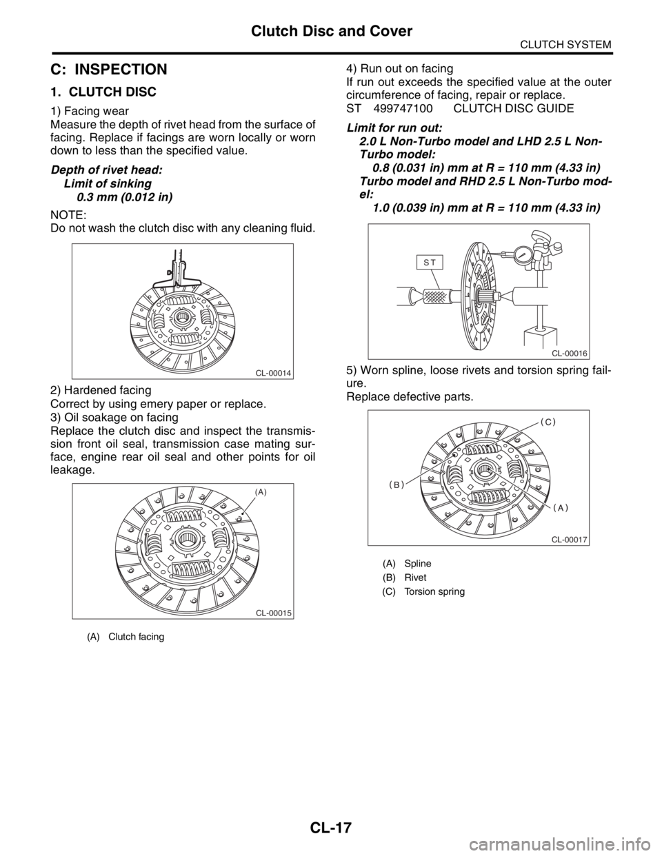
1) Facing wear
Measure the depth of rivet head from the surface of
facing. Replace if facings are worn locally or worn
down to less than the specified value.
Depth of rivet head:
Limit of sinking
0.3 mm (0.012 in)
NOTE:
Do not wash the clutch disc with any cleaning fluid.
2) Hardened facing
Correct by using emery paper or replace.
3) Oil soakage on facing
Replace the clutch disc and inspect the transmis-
sion front oil seal, transmission case mating sur-
face, engine rear oil seal and other points for oil
leakage.4) Run out on facing
If run out exceeds the specified value at the outer
circumference of facing, repair or replace.
ST 499747100 CLUTCH DISC GUIDE
Limit for run out:
2.0 L Non-Turbo model and LHD 2.5 L Non-
Turbo model:
0.8 (0.031 in) mm at R = 110 mm (4.33 in)
Turbo model and RHD 2.5 L Non-Turbo mod-
el:
1.0 (0.039 in) mm at R = 110 mm (4.33 in)
5) Worn spline, loose rivets and torsion spring fail-
ure.
Replace defective parts.
(A) Clutch facing
CL-00014
CL-00015
(A)
(A) Spline
(B) Rivet
(C) Torsion spring
CL-00016
ST
CL-00017