2004 SUBARU FORESTER width
[x] Cancel search: widthPage 4 of 2870

AC-2
HVAC SYSTEM (HEATER, VENTILATOR AND A/C)
General Description
1. General Description
A: SPECIFICATION
1. HEATER SYSTEM
2. A/C SYSTEM
AUTO A/C MODEL
Item Specifications Condition
Heating capacity5.0 kW (4,300 kcal/h,
17,062 BTU/h) or more• Mode selector switch: HEAT
• Temperature control switch: FULL HOT
• Temperature difference between hot water
and inlet air: 65°C (149°F)
• Hot water flow rate: 3602 (95.1 US gal, 79.2
Imp gal)/h
Air flow rate
280 m
3 (9,888 cu ft)/hHeat mode (FRESH), FULL HOT at 12.5 V
Max air flow rate
480 m
3 (16,951 cu ft)/h• Temperature control switch: FULL COLD
• Blower fan speed: 4th position
• Mode selector lever: RECIRC
Heater core size
(height×length×width)134.1×224.3×32 mm
(5.28×8.83×1.26 in)—
Blower motorTy p eAuto A/C (Brushless motor)
230 W or less12.5 V
Manual A/C (Cylinder motor)
260 W or less12.5 V
Fan type and size
(diameter×width)Sirocco fan type
150×75 mm (5.91×2.95 in)—
Item Specifications
Type of air conditioner Reheat air-mix type
Cooling capacity5.1 kW
(4,386 kcal/h, 17,403 BTU/h)
RefrigerantHFC-134a (CH
2FCF3)
[0.6±0.05 kg (1.32±0.11 lb)]
CompressorType Vane rotary, fix volume (DKV-14G)
Discharge
140 cm
3 (8.54 cu in)/rev
Max. permissible speed 7,000 rpm
Magnet clutchType Dry, single-disc type
Power consumption 38 W (DC 12 V-25°C)
Type of belt V-belt 4 PK
Pulley dia. (effective dia.) 125 mm (4.92 in)
Pulley ratio 1.064
CondenserType Corrugated fin (Sub cool type)
Core face area
0.234 m
2 (2.52 sq ft)
Core thickness 16 mm (0.63 in)
Radiation area
5.6 m
2 (62.28 sq ft)
Receiver drier Effective inner capacity
220 cm
3 (13.42 cu in)
Expansion valve Type External equalizing
EvaporatorType Single tank
Dimensions (W×H×T)176.5×266×60 mm
(6.95×10.47×2.36 in)
Blower fanFan type Sirocco fan
Outer diameter×width 150×75 mm (5.91×2.95 in)
Power consumption 230 W or less at 12.5 V
Page 6 of 2870

AC-4
HVAC SYSTEM (HEATER, VENTILATOR AND A/C)
General Description
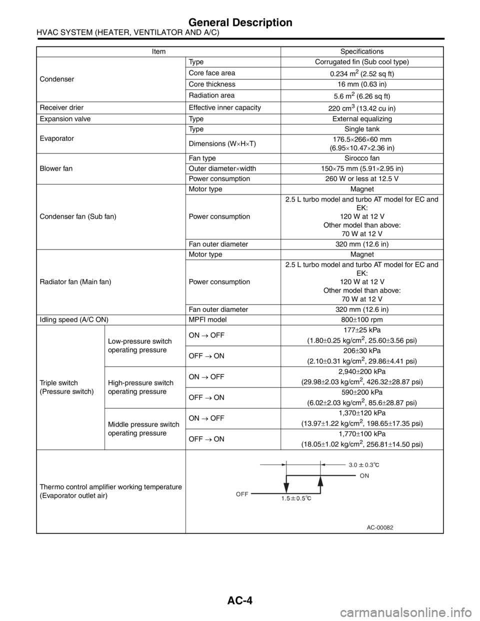
CondenserType Corrugated fin (Sub cool type)
Core face area
0.234 m
2 (2.52 sq ft)
Core thickness 16 mm (0.63 in)
Radiation area
5.6 m
2 (6.26 sq ft)
Receiver drier Effective inner capacity
220 cm
3 (13.42 cu in)
Expansion valve Type External equalizing
EvaporatorType Single tank
Dimensions (W×H×T)176.5×266×60 mm
(6.95×10.47×2.36 in)
Blower fanFan type Sirocco fan
Outer diameter×width 150×75 mm (5.91×2.95 in)
Power consumption 260 W or less at 12.5 V
Condenser fan (Sub fan)Motor type Magnet
Power consumption2.5 L turbo model and turbo AT model for EC and
EK:
120 W at 12 V
Other model than above:
70 W at 12 V
Fan outer diameter 320 mm (12.6 in)
Radiator fan (Main fan)Motor type Magnet
Power consumption2.5 L turbo model and turbo AT model for EC and
EK:
120 W at 12 V
Other model than above:
70 W at 12 V
Fan outer diameter 320 mm (12.6 in)
Idling speed (A/C ON) MPFI model 800±100 rpm
Triple switch
(Pressure switch)Low-pressure switch
operating pressureON → OFF177±25 kPa
(1.80±0.25 kg/cm
2, 25.60±3.56 psi)
OFF → ON206±30 kPa
(2.10±0.31 kg/cm
2, 29.86±4.41 psi)
High-pressure switch
operating pressureON → OFF2,940±200 kPa
(29.98±2.03 kg/cm
2, 426.32±28.87 psi)
OFF → ON590±200 kPa
(6.02±2.03 kg/cm
2, 85.6±28.87 psi)
Middle pressure switch
operating pressureON → OFF1,370±120 kPa
(13.97±1.22 kg/cm
2, 198.65±17.35 psi)
OFF → ON1,770±100 kPa
(18.05±1.02 kg/cm
2, 256.81±14.50 psi)
Thermo control amplifier working temperature
(Evaporator outlet air)Item Specifications
AC-00082
OFFON
3.0
0.3
Page 510 of 2870

EI-34
EXTERIOR/INTERIOR TRIM
Side Garnish
10.Side Garnish
A: REMOVAL
1) Incise the edge of garnish using cutter, and then
remove the garnish with pulling towards you by
hands.
NOTE:
Remove the garnish carefully. Forced removal of
garnish may damage garnish and clips.
2) Adhere the masking tape around area where the
double-sided tape of side garnish was adhere.
3) Apply the solvent (SUMITOMO 3M 4000 or equiv-
alent) to the area where double-sided tape was ad-
hered.
NOTE:
Wipe off immediately when the solvent is touched
on the garnish surface.
Do not use the solvent to the body which repaired
with lacquer paint.
4) Cover the area where the solvent applied using
plastic wrap, and then heat the double-sided tape
was adhered for 5 to 15 minutes in 40 to 60°C (104
to 140°F) using heat lamp.
5) Remove the double-sided tape of side garnish
side tape by following above step 3) and 4).
NOTE:
When the double-sided tape is not removed com-
pletely using above steps, use the scraper.
B: INSTALLATION
1) Apply the PRIMER (SUMITOMO 3M K-500 or
equivalent) widely to the slightly larger area where
double-sided tape was adhered, and then adhere
the double-sided tape (SUMITOMO 3M 5305 or
equivalent).
NOTE:
Use 5 mm (0.2 in) width and 1 mm (0.04 in) thick-
ness double-sided tape.
2) Heat the vehicle body to 40 to 60°C (104 to
140°F) and garnish to 20 to 30°C (68 to 86°F) using
heat lamp.
3) Remove the double-sided tape backing sheet, and
then align the clips to vehicle body holes. Press and
install the side garnish applying 69 — 98 N (7 — 10
kgf, 15 — 22 lbf) by the hands, using care to avoid air
entering.
NOTE:
To keep the adhesion, do not wash the vehicle
within 24 hours.
After the adhesion, use care not to move the side
garnish up and down.
C: INSPECTION
Check the side garnish is not damaged or
cracked.
Check the clips are not broken.
(1) Double-sided tape
(2) Front side
EI-00109
(1)
(2)
EI-00110
(1)
(2)
Page 691 of 2870

SPC-2
SPECIFICATION
Forester
1. Forester
A: DIMENSIONS
★: With sunroof
B: ENGINE
Model 2.0 L Non-turbo 2.0 L Turbo 2.5 L Non-turbo 2.5 L Turbo
Overall length mm (in) 4,450 (175.2)
Overall width mm (in) 1,735 (68.3)
Overall height (at C.W.) mm (in) 1,590 (62.6) 1,585 (62.4) 1,590 (62.6)
CompartmentLength mm (in) 1,795 (70.7)
Width mm (in) 1,455 (57.3)
Height mm (in)
1,245 (49.0), 1,210 (47.6)
★
Wheelbase mm (in) 2,525 (99.4)
Tread Front mm (in) 1,495 (58.9)
Rear mm (in) 1,485 (58.5)
Minimum road clearance mm (in) 190 (7.5) 195 (7.7) 200 (7.9)
Model 2.0 L Non-turbo 2.0 L Turbo 2.5 L Non-turbo 2.5 L Turbo
Engine type Horizontally opposed, liquid cooled, 4-cylinder, 4-stroke gasoline engine
Valve arrangement Overhead camshaft type
Bore×Stroke mm (in) 92×75 (3.62×2.95) 99.5×79 (3.92×3.11)
Displacement
cm
3 (cu in)1,994 (121.67) 2,457 (149.94)
Compression ratio 10.0±0.2 8.0±0.2 10.0±0.2 8.2±0.2
Firing order 1 — 3 — 2 — 4
Idle speed at Park or Neu-
tral positionrpm 650±100 700±100 650±100 700±100
Maximum output kW (PS)/rpm 92 (125)/5,600 130 (177)/5,600 115 (156)/5,600 155 (211)/5,600
Maximum torque N⋅m (kgf-m, ft-lb)/rpm184 (18.8, 41.4)/
3,600245 (25.0, 55.1)/
3,200223 (22.7, 50.1)/
3,600320 (32.6, 71.8)/
3,600
Page 752 of 2870

PM-15
PERIODIC MAINTENANCE SERVICE
Timing Belt
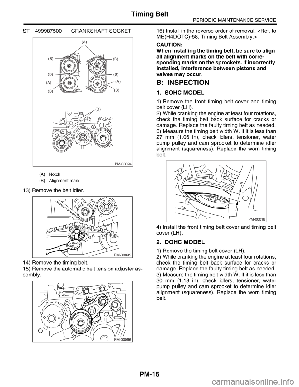
ST 499987500 CRANKSHAFT SOCKET
13) Remove the belt idler.
14) Remove the timing belt.
15) Remove the automatic belt tension adjuster as-
sembly.16) Install in the reverse order of removal.
CAUTION:
When installing the timing belt, be sure to align
all alignment marks on the belt with corre-
sponding marks on the sprockets. If incorrectly
installed, interference between pistons and
valves may occur.
B: INSPECTION
1. SOHC MODEL
1) Remove the front timing belt cover and timing
belt cover (LH).
2) While cranking the engine at least four rotations,
check the timing belt back surface for cracks or
damage. Replace the faulty timing belt as needed.
3) Measure the timing belt width W. If it is less than
27 mm (1.06 in), check idlers, tensioner, water
pump pulley and cam sprocket to determine idler
alignment (squareness). Replace the worn timing
belt.
4) Install the front timing belt cover and timing belt
cover (LH).
2. DOHC MODEL
1) Remove the timing belt cover (LH).
2) While cranking the engine at least four rotations,
check the timing belt back surface for cracks or
damage. Replace the faulty timing belt as needed.
3) Measure the timing belt width W. If it is less than
30 mm (1.18 in), check idlers, tensioner, water
pump pulley and cam sprocket to determine idler
alignment (squareness). Replace the worn timing
belt.
(A) Notch
(B) Alignment mark
PM-00094
(A)
(B)
(B)
(B) (A)(B)
(B)
(B)(A)
(B)
PM-00095
PM-00096
w
PM-00016
Page 872 of 2870

ME(H4SO)-3
MECHANICAL
General Description
Cylinder
headSurface warpage limit (mating with cylinder block) mm (in) 0.05 (0.0020)
Grinding limit mm (in) 0.1 (0.004)
Standard height mm (in) 97.5 (3.84)
Va l ve s e a tRefacing angle90°
Contacting width mm (in)IntakeSTD 1.1 (0.043)
Limit 1.8 (0.070)
ExhaustSTD 1.5 (0.059)
Limit 2.2 (0.087)
Valve guideInner diameter mm (in) 6.000 — 6.012 (0.2362 — 0.2367)
Protrusion above head mm (in)Intake 20.0 — 20.5 (0.787 — 0.807)
Exhaust 16.5 — 17.0 (0.650 — 0.669)
Va l veHead edge thickness mm (in)IntakeSTD 1.0 (0.039)
Limit 0.6 (0.024)
ExhaustSTD 1.2 (0.047)
Limit 0.6 (0.024)
Stem outer diameter mm (in)Intake 5.950 — 5.965 (0.2343 — 0.2348)
Exhaust 5.945 — 5.960(0.2341 — 0.2346)
Stem oil clearance mm (in)STDIntake 0.035 — 0.062 (0.0014 — 0.0024)
Exhaust 0.040 — 0.067 (0.0016 — 0.0026)
Limit — 0.15 (0.0059)
Overall length mm (in)Intake 120.6 (4.75)
Exhaust 121.7 (4.79)
Valve springFree length mm (in) 54.30 (2.1378)
Squareness mm (in) 2.5°, 2.4 (0.094)
Tension/spring height N (kgf, lb)/mm (in)Set214 — 246 (22 — 25, 48 — 55)/
45.0 (1.772)
Lift526 — 582 (54 — 59, 119 — 130)/
34.7 (1.366)
Cylinder
blockSurface warpage limit (mating with cylinder head) mm (in) 0.05 (0.0020)
Grinding limit mm (in) 0.1 (0.004)
Cylinder inner
diametermm (in)2.0 L STDA 92.005 — 92.015 (3.6222 — 3.6226)
B 91.995 — 92.005 (3.6218 — 3.6222)
2.5 L STDA 99.505 — 99.515 (3.9175 — 3.9179)
B 99.495 — 99.505 (3.9171 — 3.9175)
Ta p e r m m ( i n )STD 0.015 (0.0006)
Limit 0.050 (0.0020)
Out-of-roundness mm (in)STD 0.010 (0.0004)
Limit 0.050 (0.0020)
Piston clearance mm (in)STD 0.010 — 0.030 (0.0004 — 0.0012)
Limit 0.050 (0.0020)
Boring mm (in) 0.5 (0.020)
PistonOuter diameter mm (in)2.0 LSTDA 91.985 — 91.995 (3.6214 — 3.6218)
B 91.975 — 91.985 (3.6211 — 3.6214)
0.25 (0.0098) OS 92.225 — 92.235 (3.6309 — 3.6313)
0.50 (0.0197) OS 92.475 — 92.485 (3.6407 — 3.6411)
2.5 LSTDA 99.485 — 99.495 (3.9167 — 3.9171)
B 99.475 — 99.485 (3.9163 — 3.9167)
0.25 (0.0098) OS 99.725 — 99.735 (3.9262 — 3.9266)
0.50 (0.0197) OS 99.975 — 99.985 (3.9360 — 3.9364)
Piston pin standard diameter mm (in) 23.000 — 23.006 (0.9055 — 0.9057)
Page 937 of 2870

ME(H4SO)-66
MECHANICAL
Cylinder Head
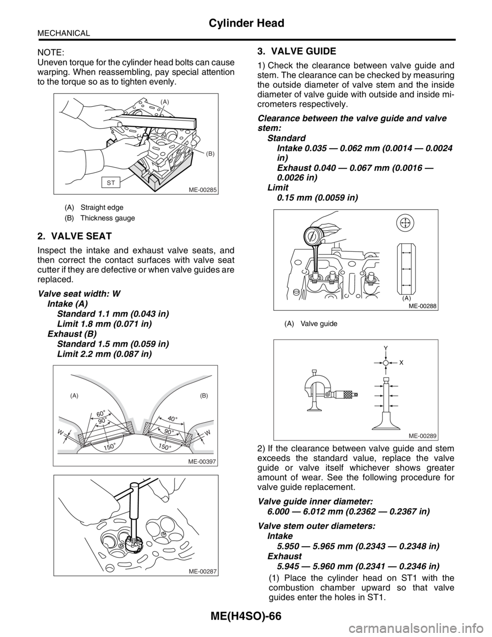
NOTE:
Uneven torque for the cylinder head bolts can cause
warping. When reassembling, pay special attention
to the torque so as to tighten evenly.
2. VALVE SEAT
Inspect the intake and exhaust valve seats, and
then correct the contact surfaces with valve seat
cutter if they are defective or when valve guides are
replaced.
Valve seat width: W
Intake (A)
Standard 1.1 mm (0.043 in)
Limit 1.8 mm (0.071 in)
Exhaust (B)
Standard 1.5 mm (0.059 in)
Limit 2.2 mm (0.087 in)
3. VALVE GUIDE
1) Check the clearance between valve guide and
stem. The clearance can be checked by measuring
the outside diameter of valve stem and the inside
diameter of valve guide with outside and inside mi-
crometers respectively.
Clearance between the valve guide and valve
stem:
Standard
Intake 0.035 — 0.062 mm (0.0014 — 0.0024
in)
Exhaust 0.040 — 0.067 mm (0.0016 —
0.0026 in)
Limit
0.15 mm (0.0059 in)
2) If the clearance between valve guide and stem
exceeds the standard value, replace the valve
guide or valve itself whichever shows greater
amount of wear. See the following procedure for
valve guide replacement.
Valve guide inner diameter:
6.000 — 6.012 mm (0.2362 — 0.2367 in)
Valve stem outer diameters:
Intake
5.950 — 5.965 mm (0.2343 — 0.2348 in)
Exhaust
5.945 — 5.960 mm (0.2341 — 0.2346 in)
(1) Place the cylinder head on ST1 with the
combustion chamber upward so that valve
guides enter the holes in ST1.
(A) Straight edge
(B) Thickness gauge
ST(A)
(B)
ME-00285
WW
(A) (B)
ME-00397
ME-00287
(A) Valve guide
(A)
ME-00288
ME-00289
X Y
Page 986 of 2870

CO(H4SO)-3
COOLING
General Description
★1: For option code, refer to ID section.
Core dimensions Width×Height×Thickness691.5×360×16 mm
(27.22×14.17×0.63 in)
Pressure range in which cap valve is openAbove: 108±15 kPa
(1.1±0.15 kg/cm
2, 16±2 psi)
Below: −1.0 to −4.9 kPa
(−0.01 to −0.05 kg/cm
2, −0.1 to −0.7 psi)
Fins Corrugated fin type
Reservoir
tankCapacity 0.52 (0.5 US qt, 0.4 Imp qt)