2004 NISSAN TERRANO cooling
[x] Cancel search: coolingPage 716 of 1833
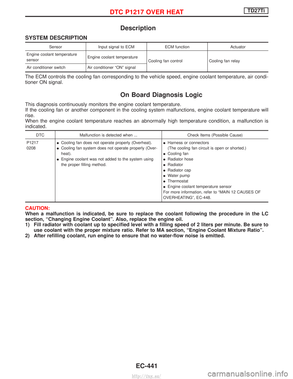
Description
SYSTEM DESCRIPTION
SensorInput signal to ECM ECM functionActuator
Engine coolant temperature
sensor Engine coolant temperature
Cooling fan control Cooling fan relay
Air conditioner switch Air conditioner ªONº signal
The ECM controls the cooling fan corresponding to the vehicle speed, engine coolant temperature, air condi-
tioner ON signal.
On Board Diagnosis Logic
This diagnosis continuously monitors the engine coolant temperature.
If the cooling fan or another component in the cooling system malfunctions, engine coolant temperature will
rise.
When the engine coolant temperature reaches an abnormally high temperature condition, a malfunction is
indicated.
DTC Malfunction is detected when ... Check Items (Possible Cause)
P1217
0208 I
Cooling fan does not operate properly (Overheat).
I Cooling fan system does not operate properly (Over-
heat).
I Engine coolant was not added to the system using
the proper filling method. I
Harness or connectors
(The cooling fan circuit is open or shorted.)
I Cooling fan
I Radiator hose
I Radiator
I Radiator cap
I Water pump
I Thermostat
I Engine coolant temperature sensor
For more information, refer to ªMAIN 12 CAUSES OF
OVERHEATINGº, EC-448.
CAUTION:
When a malfunction is indicated, be sure to replace the coolant following the procedure in the LC
section, ªChanging Engine Coolantº. Also, replace the engine oil.
1) Fill radiator with coolant up to specified level with a filling speed of 2 liters per minute. Be sure to use coolant with the proper mixture ratio. Refer to MA section, ªEngine Coolant Mixture Ratioº.
2) After refilling coolant, run engine to ensure that no water-flow noise is emitted.
DTC P1217 OVER HEATTD27Ti
EC-441
http://vnx.su/
Page 717 of 1833
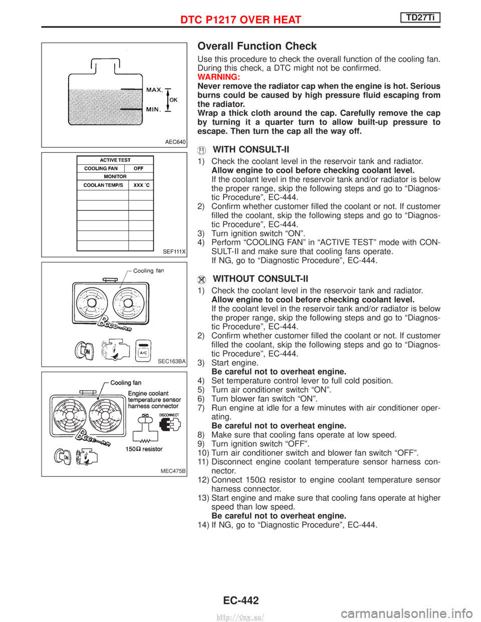
Overall Function Check
Use this procedure to check the overall function of the cooling fan.
During this check, a DTC might not be confirmed.
WARNING:
Never remove the radiator cap when the engine is hot. Serious
burns could be caused by high pressure fluid escaping from
the radiator.
Wrap a thick cloth around the cap. Carefully remove the cap
by turning it a quarter turn to allow built-up pressure to
escape. Then turn the cap all the way off.
WITH CONSULT-II
1) Check the coolant level in the reservoir tank and radiator.Allow engine to cool before checking coolant level.
If the coolant level in the reservoir tank and/or radiator is below
the proper range, skip the following steps and go to ªDiagnos-
tic Procedureº, EC-444.
2) Confirm whether customer filled the coolant or not. If customer filled the coolant, skip the following steps and go to ªDiagnos-
tic Procedureº, EC-444.
3) Turn ignition switch ªONº.
4) Perform ªCOOLING FANº in ªACTIVE TESTº mode with CON- SULT-II and make sure that cooling fans operate.
If NG, go to ªDiagnostic Procedureº, EC-444.
WITHOUT CONSULT-II
1) Check the coolant level in the reservoir tank and radiator.Allow engine to cool before checking coolant level.
If the coolant level in the reservoir tank and/or radiator is below
the proper range, skip the following steps and go to ªDiagnos-
tic Procedureº, EC-444.
2) Confirm whether customer filled the coolant or not. If customer filled the coolant, skip the following steps and go to ªDiagnos-
tic Procedureº, EC-444.
3) Start engine. Be careful not to overheat engine.
4) Set temperature control lever to full cold position.
5) Turn air conditioner switch ªONº.
6) Turn blower fan switch ªONº.
7) Run engine at idle for a few minutes with air conditioner oper- ating.
Be careful not to overheat engine.
8) Make sure that cooling fans operate at low speed.
9) Turn ignition switch ªOFFº.
10) Turn air conditioner switch and blower fan switch ªOFFº.
11) Disconnect engine coolant temperature sensor harness con- nector.
12) Connect 150W resistor to engine coolant temperature sensor
harness connector.
13) Start engine and make sure that cooling fans operate at higher speed than low speed.
Be careful not to overheat engine.
14) If NG, go to ªDiagnostic Procedureº, EC-444.
AEC640
SEF111X
SEC163BA
MEC475B
DTC P1217 OVER HEATTD27Ti
EC-442
http://vnx.su/
Page 719 of 1833
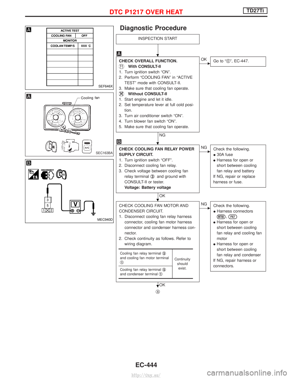
Diagnostic Procedure
INSPECTION START
CHECK OVERALL FUNCTION.
With CONSULT-II
1. Turn ignition switch ªONº.
2. Perform ªCOOLING FANº in ªACTIVE TESTº mode with CONSULT-II.
3. Make sure that cooling fan operate.
Without CONSULT-II
1. Start engine and let it idle.
2. Set temperature lever at full cold posi- tion.
3. Turn air conditioner switch ªONº.
4. Turn blower fan switch ªONº.
5. Make sure that cooling fan operate.
NG
EOK Go to ª qCº, EC-447.
CHECK COOLING FAN RELAY POWER
SUPPLY CIRCUIT.
1. Turn ignition switch ªOFFº.
2. Disconnect cooling fan relay.
3. Check voltage between cooling fan relay terminal q
3and ground with
CONSULT-II or tester.
Voltage: Battery voltage
OK
ENG Check the following.
I30A fuse
I Harness for open or
short between cooling
fan relay and battery
If NG, repair or replace
harness or fuse.
CHECK COOLING FAN MOTOR AND
CONDENSER CIRCUIT.
1. Disconnect cooling fan relay harness connector, cooling fan motor harness
connector and condenser harness con-
nector.
2. Check continuity as follows. Refer to wiring diagram.
OK
ENG Check the following.
IHarness connectors
M785,F67
IHarness for open or
short between cooling
fan relay and cooling fan
motor
I Harness for open or
short between cooling
fan relay and condenser
If NG, repair harness or
connectors.
qA
Cooling fan relay terminal q5and cooling fan motor terminal
q1Continuity
shouldexist.
Cooling fan relay terminal q
5and condenser terminalq1
SEF646X
SEC163BA
MEC940D
H
H
H
H
DTC P1217 OVER HEATTD27Ti
EC-444
http://vnx.su/
Page 720 of 1833
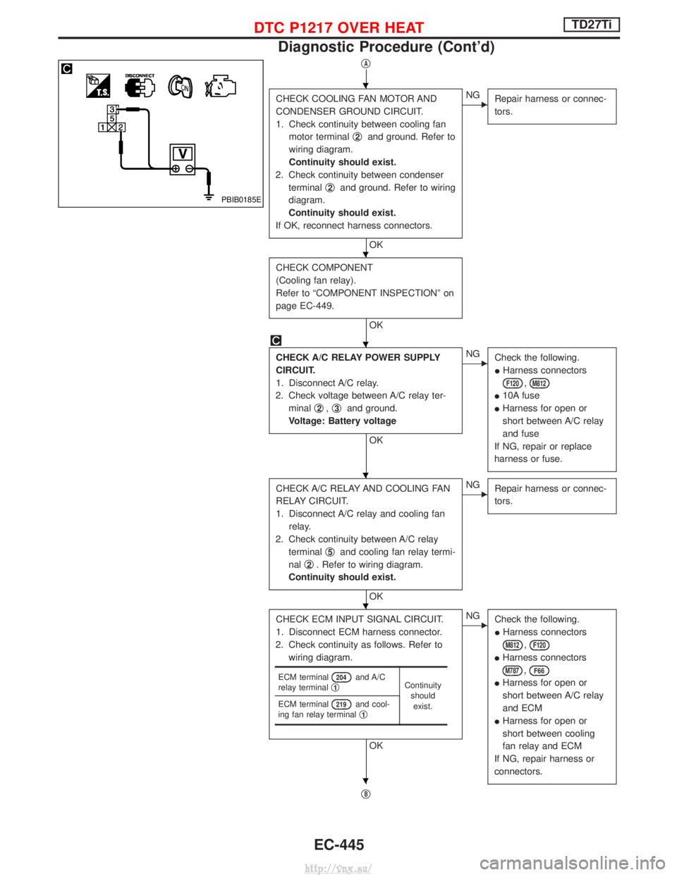
qA
CHECK COOLING FAN MOTOR AND
CONDENSER GROUND CIRCUIT.
1. Check continuity between cooling fanmotor terminal q
2and ground. Refer to
wiring diagram.
Continuity should exist.
2. Check continuity between condenser terminal q
2and ground. Refer to wiring
diagram.
Continuity should exist.
If OK, reconnect harness connectors.
OK
ENG Repair harness or connec-
tors.
CHECK COMPONENT
(Cooling fan relay).
Refer to ªCOMPONENT INSPECTIONº on
page EC-449.
OK
CHECK A/C RELAY POWER SUPPLY
CIRCUIT.
1. Disconnect A/C relay.
2. Check voltage between A/C relay ter- minal q
2,q3and ground.
Voltage: Battery voltage
OK
ENG Check the following.
IHarness connectors
F120,M812
I10A fuse
I Harness for open or
short between A/C relay
and fuse
If NG, repair or replace
harness or fuse.
CHECK A/C RELAY AND COOLING FAN
RELAY CIRCUIT.
1. Disconnect A/C relay and cooling fan relay.
2. Check continuity between A/C relay terminal q
5and cooling fan relay termi-
nal q
2. Refer to wiring diagram.
Continuity should exist.
OK
ENG Repair harness or connec-
tors.
CHECK ECM INPUT SIGNAL CIRCUIT.
1. Disconnect ECM harness connector.
2. Check continuity as follows. Refer to wiring diagram.
OK
ENG Check the following.
IHarness connectors
M812,F120
IHarness connectors
M787,F66
IHarness for open or
short between A/C relay
and ECM
I Harness for open or
short between cooling
fan relay and ECM
If NG, repair harness or
connectors.
qB
ECM terminal204and A/C
relay terminal q1Continuity
shouldexist.
ECM terminal
219and cool-
ing fan relay terminal q1
PBIB0185E
H
H
H
H
H
H
DTC P1217 OVER HEATTD27Ti
Diagnostic Procedure (Cont'd)
EC-445
http://vnx.su/
Page 722 of 1833
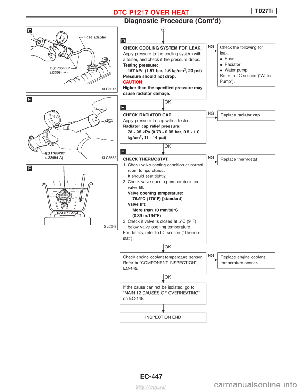
qc
CHECK COOLING SYSTEM FOR LEAK.
Apply pressure to the cooling system with
a tester, and check if the pressure drops.
Testing pressure:157 kPa (1.57 bar, 1.6 kg/cm
2, 23 psi)
Pressure should not drop.
CAUTION:
Higher than the specified pressure may
cause radiator damage.
OK
ENG Check the following for
leak.
IHose
I Radiator
I Water pump
Refer to LC section (ªWater
Pumpº).
CHECK RADIATOR CAP.
Apply pressure to cap with a tester.
Radiator cap relief pressure: 78 - 98 kPa (0.78 - 0.98 bar, 0.8 - 1.0
kg/cm
2, 11 - 14 psi)
OK
ENG Replace radiator cap.
CHECK THERMOSTAT.
1. Check valve seating condition at normal
room temperatures.
It should seat tightly.
2. Check valve opening temperature and valve lift.
Valve opening temperature:76.5ÉC (170ÉF) [standard]
Valve lift: More than 10 mm/90ÉC
(0.39 in/194ÉF)
3. Check if valve is closed at 5ÉC (9ÉF) below valve opening temperature.
For details, refer to LC section (ªThermo-
statº).
OK
ENG Replace thermostat
Check engine coolant temperature sensor.
Refer to ªCOMPONENT INSPECTIONº,
EC-449.
OK
ENGReplace engine coolant
temperature sensor.
If the cause can not be isolated, go to
ªMAIN 12 CAUSES OF OVERHEATINGº
on EC-448.
INSPECTION END
SLC754A
SLC755A
SLC343
H
H
H
H
H
H
DTC P1217 OVER HEATTD27Ti
Diagnostic Procedure (Cont'd)
EC-447
http://vnx.su/
Page 723 of 1833
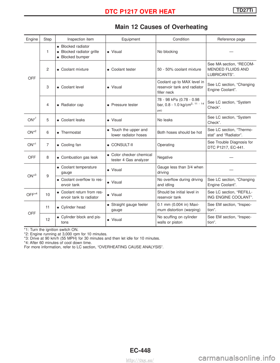
Main 12 Causes of Overheating
Engine Step Inspection itemEquipmentConditionReference page
OFF 1
I
Blocked radiator
I Blocked radiator grille
I Blocked bumper I
Visual No blocking Ð
2 ICoolant mixture ICoolant tester 50 - 50% coolant mixture See MA section, ªRECOM-
MENDED FLUIDS AND
LUBRICANTSº.
3 ICoolant level IVisual Coolant up to MAX level in
reservoir tank and radiator
filler neck See LC section, ªChanging
Engine Coolantº.
4 IRadiator cap IPressure tester 78 - 98 kPa (0.78 - 0.98
bar, 0.8 - 1.0 kg/cm
2,11-14
psi)See LC section, ªSystem
Checkº.
ON*
25 ICoolant leaks IVisual No leaks See LC section, ªSystem
Checkº.
ON*
26 IThermostat I
Touch the upper and
lower radiator hoses Both hoses should be hot See LC section, ªThermo-
statº and ªRadiatorº.
ON*
17 ICooling fan ICONSULT-II Operating See Trouble Diagnosis for
DTC P1217, EC-441.
OFF 8 ICombustion gas leak I
Color checker chemical
tester 4 Gas analyzer Negative Ð
ON*
39 I
Coolant temperature
gauge I
Visual Gauge less than 3/4 when
driving Ð
I Coolant overflow to res-
ervoir tank I
Visual No overflow during driving
and idling See LC section, ªChanging
Engine Coolantº.
OFF*
410 I
Coolant return from res-
ervoir tank to radiator I
Visual Should be initial level in
reservoir tank See LC section, ªREFILL-
ING ENGINE COOLANTº.
OFF 11
ICylinder head I
Straight gauge feeler
gauge 0.1 mm (0.004 in) Maxi-
mum distortion (warping) See EM section, ªInspec-
tionº.
12 I
Cylinder block and pis-
tons I
Visual No scuffing on cylinder
walls or piston See EM section, ªInspec-
tionº.
*1: Turn the ignition switch ON.
*2: Engine running at 3,000 rpm for 10 minutes.
*3: Drive at 90 km/h (55 MPH) for 30 minutes and then let idle for 10 minutes.
*4: After 60 minutes of cool down time.
For more information, refer to LC section, ªOVERHEATING CAUSE ANALYSISº.
DTC P1217 OVER HEATTD27Ti
EC-448
http://vnx.su/
Page 724 of 1833
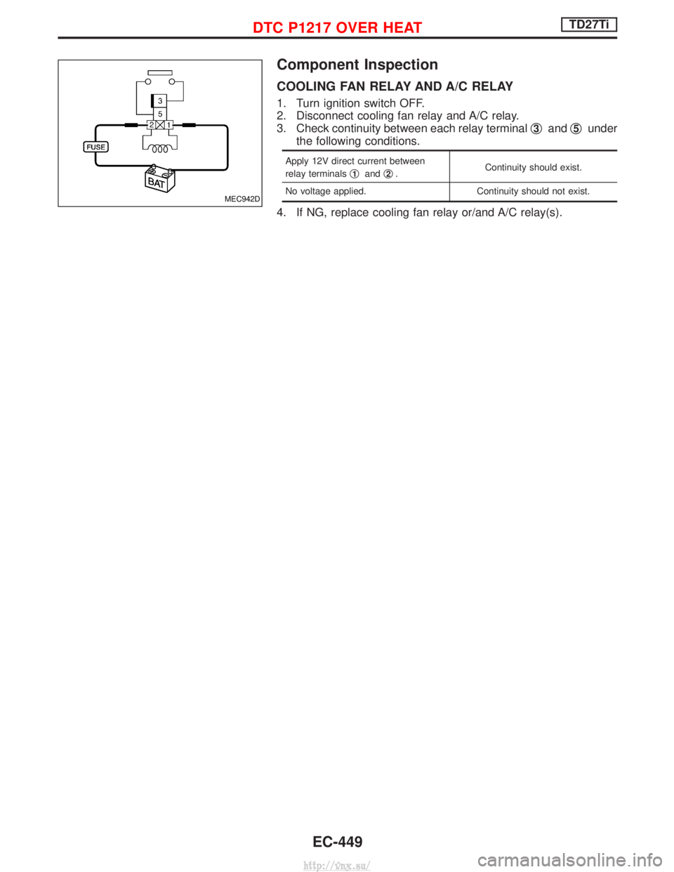
Component Inspection
COOLING FAN RELAY AND A/C RELAY
1. Turn ignition switch OFF.
2. Disconnect cooling fan relay and A/C relay.
3. Check continuity between each relay terminalq
3andq5under
the following conditions.
Apply 12V direct current between
relay terminals q
1andq2. Continuity should exist.
No voltage applied. Continuity should not exist.
4. If NG, replace cooling fan relay or/and A/C relay(s).
MEC942D
DTC P1217 OVER HEATTD27Ti
EC-449
http://vnx.su/
Page 818 of 1833
IBefore assembly, apply a coat of recommended ATF to all parts. Apply petroleum jelly to protect O-rings
and seals, and to hold bearings and washers in place during assembly. Do not use grease.
I Extreme care should be taken to avoid damage to O-rings, seals and gaskets when assembling.
I After overhaul, refill the transmission with new ATF.
I When the A/T drain plug is removed, only some of the fluid is drained. Old A/T fluid will remain in torque
converter and ATF cooling system.
Always follow the procedures under ªChanging A/T Fluidº in the MA section when changing A/T fluid.
Service Notice or Precautions
FAIL-SAFE
The TCM has an electronic Fail-Safe (limp home mode). This allows the vehicle to be driven even if a major
electrical input/output device circuit is damaged.
Under Fail-Safe, the vehicle always runs in third gear even with a shift lever position of ª1º, ª2º or ªDº. Cus-
tomer may complain of ªsluggish or poor accelerationº.
When the Fail-Safe operation occurs the next time the key is turned to the ªONº position, the SPORT indica-
tor lamp will blink for about 8 seconds. (For diagnosis, refer to AT-33.)
Fail-Safe may activate without electrical circuit damages if the vehicle is driven under extreme conditions (such
as excessive wheel spins and emergency braking immediately afterwards). In this case, turn the ignition key
ªOFFº for 5 seconds and then ªONº to recover normal shift pattern.
The blinking of the SPORT indicator lamp for about 8 seconds will appear only once and be cleared. The cus-
tomer may resume normal driving conditions by chance.
Always follow the ªWORK FLOWº (Refer to AT-26).
The SELF-DIAGNOSIS results will be as follows:
The first SELF-DIAGNOSIS will indicate the damage of the vehicle speed sensor or the revolution sensor.
During the next SELF-DIAGNOSIS performed after checking the sensor, no damages will be indicated.
PREPARATION AND PRECAUTIONS
Precautions (Cont'd)
AT- 5
http://vnx.su/