Page 270 of 1833
Water Pump
REMOVAL AND INSTALLATION
Drain coolant from drain plugs on cylinder block and radiator.Cylinder block drain plug:
(Use proper sealant)
:20-29N ×m (2.0 - 3.0 kg-m, 14 - 22 ft-lb)
CAUTION:
I When removing water pump assembly, be careful not to
spill coolant on drive belt.
I Water pump cannot be disassembled and should be
replaced as a unit.
I Always replace with new gasket.
I After installing water pump, connect hose and clamp
securely, then check for leaks using radiator cap tester.
NLC012
NLC058
ENGINE COOLING SYSTEMTD27Ti
LC-29
http://vnx.su/
Page 271 of 1833
INSPECTION
1. Check for badly rusted or corroded body assembly and vane.
2. Check the water pump bushing for excessive end play andirregular movement.
3. Check fan coupling for rough operation, oil leakage or bent bimetal.
The water pump and fan coupling cannot be disassembled and
should be replaced as a unit.
SLC979
SLC244
SLC245
ENGINE COOLING SYSTEMTD27Ti
Water Pump (Cont'd)
LC-30
http://vnx.su/
Page 272 of 1833
Thermostat
q1Water outlet
q
2Thermostat with jiggle valve
q
3Rubber seal q
4Water connector
q
5Thermostat housing q
6Engine coolant temperature sen-
sor
q
7Thermal transmitter
CAUTION:
I After installation, run engine for a few minutes, and check
for leaks.
I Be careful not to spill coolant over engine compartment.
Place a rag to absorb coolant.
INSPECTION
1. Check for valve seating condition at ordinary temperatures. It
should seat tightly.
2. Check valve opening temperature and maximum valve lift.
Valve opening temperature ÉC (ÉF) 88 (190)
Max. valve lift mm/ÉC (in/ÉF)8/100
(0.315/212)
3. Then check if valve closes at 5ÉC (9ÉF) below valve opening temperature.
NLC059
SLC343
ENGINE COOLING SYSTEMTD27Ti
LC-31
http://vnx.su/
Page 273 of 1833
Radiator
CAUTION:
When filling radiator with coolant, refer to MA section.
NLC082
ENGINE COOLING SYSTEMTD27Ti
LC-32
http://vnx.su/
Page 274 of 1833
Cooling Fan
DISASSEMBLY AND ASSEMBLY
IProper alignment of components is essential.
Improper alignment will cause them to wobble and may even-
tually cause the fan to separate from the water pump causing
extensive damage.
I If front mark q
Fis present, install fan so that side marked qF
faces the front.
INSPECTION
Check fan coupling for irregular operation, oil leakage or bent
bimetal.
YLC041
SLC072
ENGINE COOLING SYSTEMTD27Ti
LC-33
http://vnx.su/
Page 275 of 1833
Engine Lubrication System
Oil pressure check
Engine rpmApproximate discharge pressure
kPa (bar, kg/cm2, psi)
Idle speed More than 78 (0.78, 0.8, 11)
3,000 294 - 392 (2.94 - 3.92, 3.0 - 4.0, 43 - 57)
Oil pump
Unit: mm (in)
Gear side clearance Less than 0.13 (0.0051)
Gear backlash Less than 0.43 (0.0169)
Oil pump bushing clearance Less than 0.15 (0.0059)
Oil pump bushing inside diameter 13.012 - 13.098
(0.5123 - 0.5157)
Drive gear shaft outside diameter 12.974 - 12.992
(0.5108 - 0.5115)
Engine Cooling System
Thermostat
Valve opening temperature ÉC (ÉF)88 (190)
Max. Valve lift mm/ÉC (in/ÉF) 8/100
(0.315/212)
Radiator
Unit: kPa (bar, kg/cm2, psi)
Cap relief pressure 78-98
(0.78 - 0.98, 0.8 - 1.0, 11 - 14)
Leakage test pressure 157 (1.57, 1.6, 23)
SERVICE DATA AND SPECIFICATIONS (SDS)TD27Ti
LC-34
http://vnx.su/
Page 294 of 1833

System Chart
Input (Sensor)ECM FunctionOutput (Actuator)
I Electronic control fuel injection pump
I Crankshaft position sensor (TDC)
I Engine coolant temperature sensor
I Accelerator position sensor
I Accelerator position switch
I Accelerator switch (F/C)
I Park/Neutral position (PNP) switch
I Ignition switch
I Battery voltage
I Vehicle speed sensor
I Air conditioner switch
I Mass air flow sensor
I Stop lamp switch
I Heat up switch
I Charge air pressure sensor*1 Fuel injection control
Electronic control fuel injection pump
Fuel injection timing control Electronic control fuel injection pump
Fuel cut control Electronic control fuel injection pump
Glow control system Glow relay & glow lamp
On board diagnostic system MI (On the instrument panel)
EGR volume control EGR volume control valve
Cooling fan control Cooling fan relay
Air conditioning cut control Air conditioner relay
Variable nozzle turbocharger control Variable nozzle turbocharger control sole- noid valve
Swirl control valve control Swirl control valve control solenoid valve
Intake air control valve control Intake air control valve control solenoid
valve
*1: This sensor is not used to control the engine system under normal conditions.
ENGINE AND EMISSION CONTROL OVERALL SYSTEMZD30DDTi
EC-19
http://vnx.su/
Page 303 of 1833

REMOVAL
1. Remove the following:
IEngine coolant draining
I Charge air cooler
I Air inlet pipe
I Throttle body
I Rocker cover
I Oil level gauge guide
I EGR cooler
I EGR guide tube
I EGR volume control solenoid valve
I Fuel hose
I Injection tube
I Radiator upper hose
I Radiator shroud
I Cooling fan
I Drive belt
I Vacuum pipe
I Vacuum pump
2. Move the power steering pump.
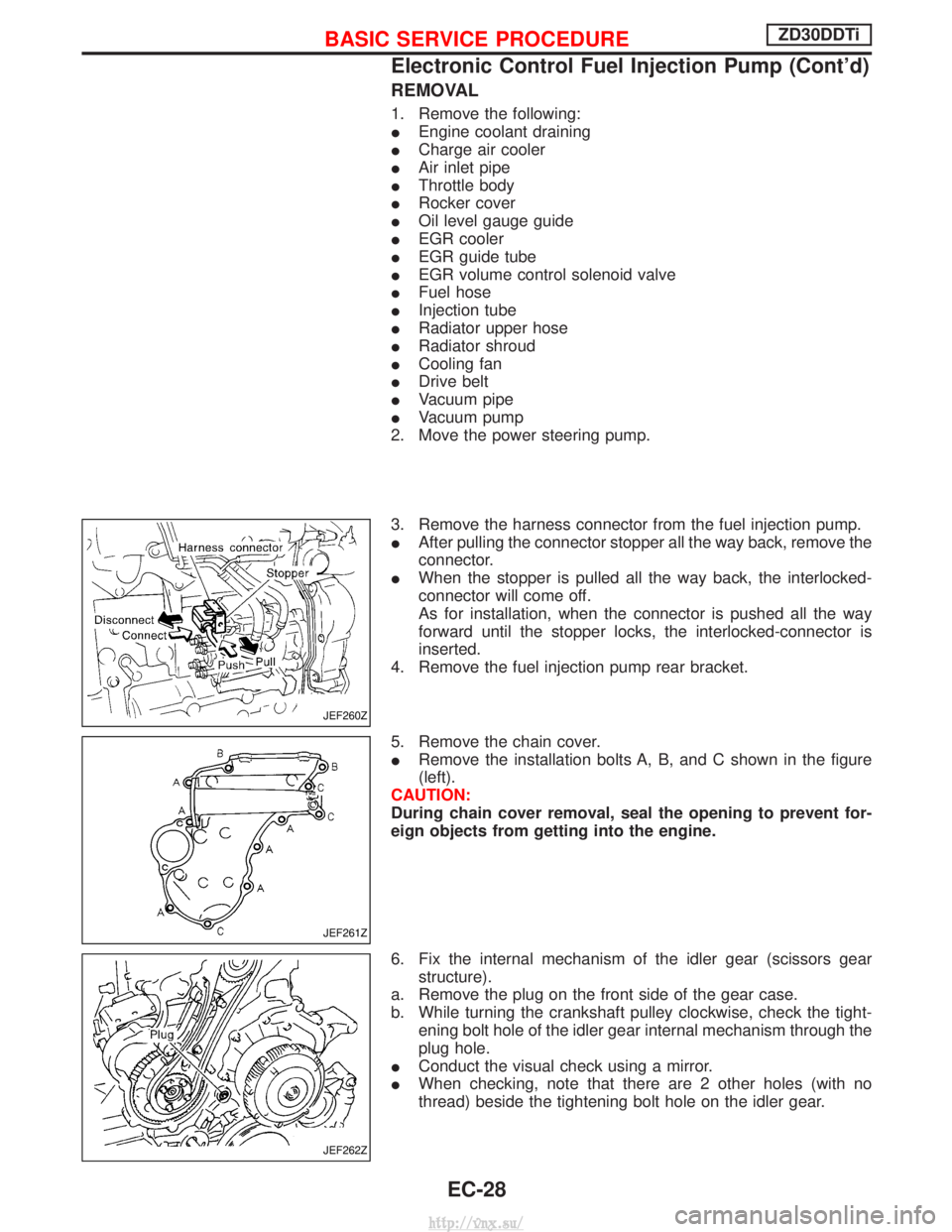
3. Remove the harness connector from the fuel injection pump.
I After pulling the connector stopper all the way back, remove the
connector.
I When the stopper is pulled all the way back, the interlocked-
connector will come off.
As for installation, when the connector is pushed all the way
forward until the stopper locks, the interlocked-connector is
inserted.
4. Remove the fuel injection pump rear bracket.
5. Remove the chain cover.
I Remove the installation bolts A, B, and C shown in the figure
(left).
CAUTION:
During chain cover removal, seal the opening to prevent for-
eign objects from getting into the engine.
6. Fix the internal mechanism of the idler gear (scissors gear structure).
a. Remove the plug on the front side of the gear case.
b. While turning the crankshaft pulley clockwise, check the tight- ening bolt hole of the idler gear internal mechanism through the
plug hole.
I Conduct the visual check using a mirror.
I When checking, note that there are 2 other holes (with no
thread) beside the tightening bolt hole on the idler gear.
JEF260Z
JEF261Z
JEF262Z
BASIC SERVICE PROCEDUREZD30DDTi
Electronic Control Fuel Injection Pump (Cont'd)
EC-28
http://vnx.su/