Page 389 of 1833
Diagnostic Procedure
1 INSPECTION START
Do you have CONSULT-II?YesorNo
Ye s EGO TO 2.
No EGO TO 3.
2 CHECK COOLING FAN OPERATION
With CONSULT-II
1. Turn ignition switch ªONº.
2. Perform ªCOOLING FANº in ªACTIVE TESTº mode with CONSULT-II.
SEF646X
3. Make sure that cooling fan operates.
OK or NG
OK EGO TO 13.
NG EGO TO 4.
3 CHECK COOLING FAN OPERATION
Without CONSULT-II
1. Turn ignition switch ªOFFº.
2. Disconnect engine coolant temperature sensor harness connector.
3. Connect 150W resistor to engine coolant temperature sensor harness connector.
4. Restart engine and make sure that cooling fan operates.
MEC475B
OK or NG
OK EGO TO 13.
NG EGO TO 4.
DTC 0208 OVER HEATZD30DDTi
EC-114
http://vnx.su/
Page 390 of 1833
4 CHECK COOLING FAN POWER SUPPLY CIRCUIT
1. Turn ignition switch ªOFFº.
2. Disconnect cooling fan relay.
MEC021E
3. Turn ignition switch ªONº.
4. Turn air conditioner switch ªONº.
5. Turn blower fan switch ªONº.
6. Check voltage between cooling fan relay terminals 2, 3 and ground with CONSULT-II or tester.
MEC974DVoltage: Battery voltageOK or NG
OK EGO TO 6.
NG EGO TO 5.
5 DETECT MALFUNCTIONING PART
Check the following.
I10A fuse
I Harness connector F120, M812 (LHD models)
I A/C relay
I 30A fusible link
I Harness for open or short between cooling fan relay and fuse
I Harness for open or short between cooling fan relay and battery
ERepair open circuit or short to ground or short to power in harness or connectors.
DTC 0208 OVER HEATZD30DDTi
Diagnostic Procedure (Cont'd)
EC-115
http://vnx.su/
Page 391 of 1833

6 CHECK COOLING FAN GROUND CIRCUIT FOR OPEN AND SHORT
1. Turn ignition switch ªOFFº.
2. Disconnect cooling fan motor harness connector.
MEC024E
3. Check harness continuity as follows. Refer to Wiring Diagram.
MTBL13224. Also check harness for short to ground and short to power.OK or NG
OK EGO TO 8.
NG EGO TO 7.
7 DETECT MALFUNCTIONING PART
Check the following.
IHarness connectors M785, F67 (M/T models)
I Harness for open or short between cooling fan relay and cooling fan motor
I Harness for open or short between cooling fan relay and condenser
I Harness for open or short between cooling fan motor and ground
I Harness for open or short between condenser and ground
ERepair open circuit or short to ground or short to power in harness or connectors.
8 CHECK COOLING FAN OUTPUT SIGNAL CIRCUIT FOR OPEN AND SHORT
1. Disconnect ECM harness connector.
2. Check harness continuity between ECM terminal 14 and cooling fan relay terminal 1. Refer to Wiring Diagram.
Continuity should exist.
3. Also check harness for short to ground and short to power.
OK or NG
OK EGO TO 10.
NG EGO TO 9.
9 DETECT MALFUNCTIONING PART
Check the following.
IHarness connectors M787, F66
I Harness for open or short between cooling fan relay and ECM
ERepair open circuit or short to ground or short to power in harness or connectors.
DTC 0208 OVER HEATZD30DDTi
Diagnostic Procedure (Cont'd)
EC-116
http://vnx.su/
Page 392 of 1833
10 CHECK COOLING FAN RELAY
Check continuity between cooling fan relay terminals 3 and 5 under the following conditions.
MEC975D
MTBL1319
OK or NG
OK EGO TO 11.
NG EReplace cooling fan relay.
11 CHECK COOLING FAN MOTOR
Supply battery voltage between cooling fan motor terminals 1 and 2.
MEC976DDoes the cooling fan motor operate normally?
OK or NG
OK EGO TO 12.
NG EReplace cooling fan motor.
12 CHECK INTERMITTENT INCIDENT
Perform ªTROUBLE DIAGNOSIS FOR INTERMITTENT INCIDENTº, EC-78.
EINSPECTION END
DTC 0208 OVER HEATZD30DDTi
Diagnostic Procedure (Cont'd)
EC-117
http://vnx.su/
Page 393 of 1833
13 CHECK COOLING SYSTEM FOR LEAK
Apply pressure to the cooling system with a tester, and check if the pressure drops.Testing pressure: 157 kPa (1.57 bar, 1.6 kg/cm
2, 23 psi)
CAUTION:
Higher than the specified pressure may cause radiator damage.
SLC754A
Pressure should not drop.
OK or NG
OK EGO TO 15.
NG EGO TO 14.
14 DETECT MALFUNCTIONING PART
Check the following for leak.
IHose
I Radiator
I Water pump (Refer to LC section, ªWater Pumpº.)
ERepair or replace.
15 CHECK RADIATOR CAP
Apply pressure to cap with a tester and check radiator cap relief pressure.
SLC755A
Radiator cap relief pressure:
79 - 98 kPa (0.78 - 0.98 bar, 0.8 - 1.0 kg/cm2, 11 - 14 psi)
OK or NG
OK EGO TO 16.
NG EReplace radiator cap.
DTC 0208 OVER HEATZD30DDTi
Diagnostic Procedure (Cont'd)
EC-118
http://vnx.su/
Page 395 of 1833

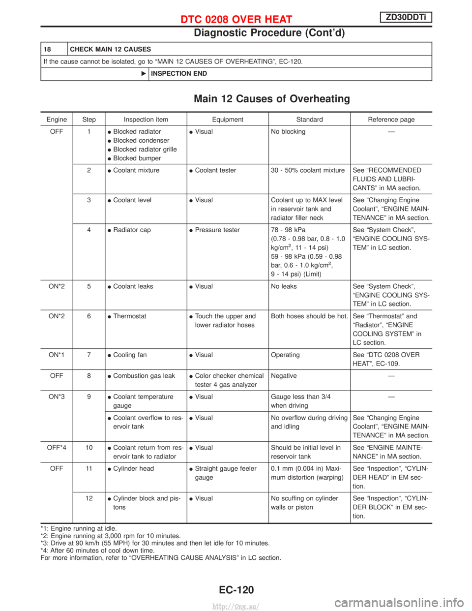
18 CHECK MAIN 12 CAUSES
If the cause cannot be isolated, go to ªMAIN 12 CAUSES OF OVERHEATINGº, EC-120.EINSPECTION END
Main 12 Causes of Overheating
Engine Step Inspection item EquipmentStandardReference page
OFF 1 IBlocked radiator
I Blocked condenser
I Blocked radiator grille
I Blocked bumper I
Visual No blocking Ð
2 ICoolant mixture ICoolant tester 30 - 50% coolant mixture See ªRECOMMENDED
FLUIDS AND LUBRI-
CANTSº in MA section.
3 ICoolant level IVisual Coolant up to MAX level
in reservoir tank and
radiator filler neck See ªChanging Engine
Coolantº, ªENGINE MAIN-
TENANCEº in MA section.
4 IRadiator cap IPressure tester 78 - 98 kPa
(0.78 - 0.98 bar, 0.8 - 1.0
kg/cm
2, 11 - 14 psi)
59 - 98 kPa (0.59 - 0.98
bar, 0.6 - 1.0 kg/cm
2,
9 - 14 psi) (Limit) See ªSystem Checkº,
ªENGINE COOLING SYS-
TEMº in LC section.
ON*2 5 ICoolant leaks IVisual No leaks See ªSystem Checkº,
ªENGINE COOLING SYS-
TEMº in LC section.
ON*2 6 IThermostat ITouch the upper and
lower radiator hoses Both hoses should be hot. See ªThermostatº and
ªRadiatorº, ªENGINE
COOLING SYSTEMº in
LC section.
ON*1 7 ICooling fan IVisual Operating See ªDTC 0208 OVER
HEATº, EC-109.
OFF 8 ICombustion gas leak IColor checker chemical
tester 4 gas analyzer Negative Ð
ON*3 9 ICoolant temperature
gauge I
Visual Gauge less than 3/4
when driving Ð
I Coolant overflow to res-
ervoir tank I
Visual No overflow during driving
and idling See ªChanging Engine
Coolantº, ªENGINE MAIN-
TENANCEº in MA section.
OFF*4 10 ICoolant return from res-
ervoir tank to radiator I
Visual Should be initial level in
reservoir tank See ªENGINE MAINTE-
NANCEº in MA section.
OFF 11 ICylinder head IStraight gauge feeler
gauge 0.1 mm (0.004 in) Maxi-
mum distortion (warping) See ªInspectionº, ªCYLIN-
DER HEADº in EM sec-
tion.
12 ICylinder block and pis-
tons I
Visual No scuffing on cylinder
walls or piston See ªInspectionº, ªCYLIN-
DER BLOCKº in EM sec-
tion.
*1: Engine running at idle.
*2: Engine running at 3,000 rpm for 10 minutes.
*3: Drive at 90 km/h (55 MPH) for 30 minutes and then let idle for 10 minutes.
*4: After 60 minutes of cool down time.
For more information, refer to ªOVERHEATING CAUSE ANALYSISº in LC section.
DTC 0208 OVER HEATZD30DDTi
Diagnostic Procedure (Cont'd)
EC-120
http://vnx.su/
Page 633 of 1833

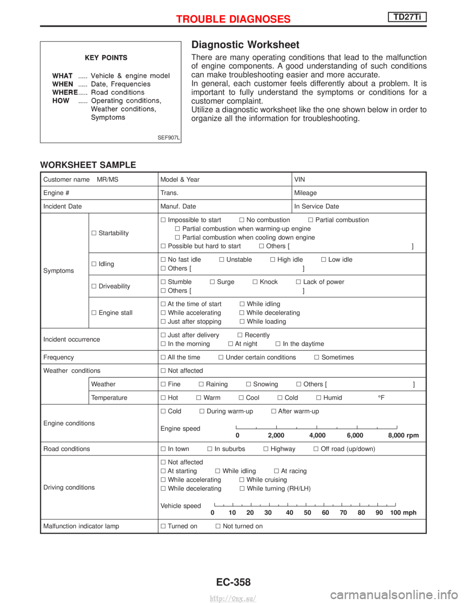
Diagnostic Worksheet
There are many operating conditions that lead to the malfunction
of engine components. A good understanding of such conditions
can make troubleshooting easier and more accurate.
In general, each customer feels differently about a problem. It is
important to fully understand the symptoms or conditions for a
customer complaint.
Utilize a diagnostic worksheet like the one shown below in order to
organize all the information for troubleshooting.
WORKSHEET SAMPLE
Customer name MR/MSModel & Year VIN
Engine # Trans. Mileage
Incident Date Manuf. Date In Service Date
Symptoms l
Startability l
Impossible to start lNo combustion lPartial combustion
l Partial combustion when warming-up engine
l Partial combustion when cooling down engine
l Possible but hard to start lOthers [ ]
l Idling l
No fast idle lUnstable lHigh idle lLow idle
l Others [ ]
l Driveability l
Stumble lSurge lKnock lLack of power
l Others [ ]
l Engine stall l
At the time of start lWhile idling
l While accelerating lWhile decelerating
l Just after stopping lWhile loading
Incident occurrence l
Just after delivery lRecently
l In the morning lAt night lIn the daytime
Frequency lAll the time lUnder certain conditions lSometimes
Weather conditions lNot affected
Weather lFine lRaining lSnowing lOthers [ ]
Temperature lHot lWarm lCool lCold lHumid ÉF
Engine conditions l
Cold lDuring warm-up lAfter warm-up
Engine speed
0 2,000 4,000 6,000 8,000 rpm
Road conditions lIn town lIn suburbs lHighway lOff road (up/down)
Driving conditions l
Not affected
l At starting lWhile idling lAt racing
l While accelerating lWhile cruising
l While decelerating lWhile turning (RH/LH)
Vehicle speed
0 102030 405060708090100mph
Malfunction indicator lamp lTurned on lNot turned on
SEF907L
TROUBLE DIAGNOSESTD27Ti
EC-358
http://vnx.su/
Page 646 of 1833
![NISSAN TERRANO 2004 Service Repair Manual TERMI-NALNO. WIRE
COLOR ITEM CONDITION DATA (DC Voltage and
Pulse Signal)
210 Y/B EGRC-solenoid valve B [Engine is running]
I
Warm-up condition
I Idle speed Approximately 0.4V
[Engine is running]
I Wa NISSAN TERRANO 2004 Service Repair Manual TERMI-NALNO. WIRE
COLOR ITEM CONDITION DATA (DC Voltage and
Pulse Signal)
210 Y/B EGRC-solenoid valve B [Engine is running]
I
Warm-up condition
I Idle speed Approximately 0.4V
[Engine is running]
I Wa](/manual-img/5/57394/w960_57394-645.png)
TERMI-NALNO. WIRE
COLOR ITEM CONDITION DATA (DC Voltage and
Pulse Signal)
210 Y/B EGRC-solenoid valve B [Engine is running]
I
Warm-up condition
I Idle speed Approximately 0.4V
[Engine is running]
I Warm-up condition
I Engine speed is 2,500 rpm BATTERY VOLTAGE
(11 - 14V)
213 G/Y Throttle control solenoid
valve [Engine is running]
I
Warm-up condition
I Low load Approximately 0V
Except above condition Battery voltage (12 - 14V)
214 LG Glow relay Refer to ªGlow Control Systemº, EC-412.
215 L Malfunction indicator (MI) [Ignition switch ªONº]
Approximately 1.0V
[Engine is running]
I Idle speed BATTERY VOLTAGE
(11 - 14V)
218 G/R Sensors' ground [Engine is running]
I
Warm-up condition
I Idle speed Approximately 0V
219 LG/R Cooling fan relay [Engine is running]
I
Cooling fan is not operating BATTERY VOLTAGE
(11 - 14V)
[Engine is running]
I Cooling fan is operating Approximately 0.1V
221 G/W Glow lamp [Ignition switch ªONº]
I
Glow lamp is ªONº Approximately 1V
[Ignition switch ªONº]
I Glow lamp is ªOFFº BATTERY VOLTAGE
(11 - 14V)
223 R/L Mass air flow sensor
power supply [Ignition switch ªONº]
Approximately 5V
224 L/W Mass air flow sensor [Engine is running]
I
Warm-up condition
I Idle speed 1.5 - 2.0V
320 W Control sleeve position
sensor [Engine is running]
I
Idle speed Approximately 2.6V
NEF477
321 R
Control sleeve position
sensor power supply [Engine is running]
I
Idle speed Approximately 2.6V
NEF476
TROUBLE DIAGNOSESTD27Ti
ECM Terminals and Reference Value (Cont'd)
EC-371
http://vnx.su/