Page 151 of 1833

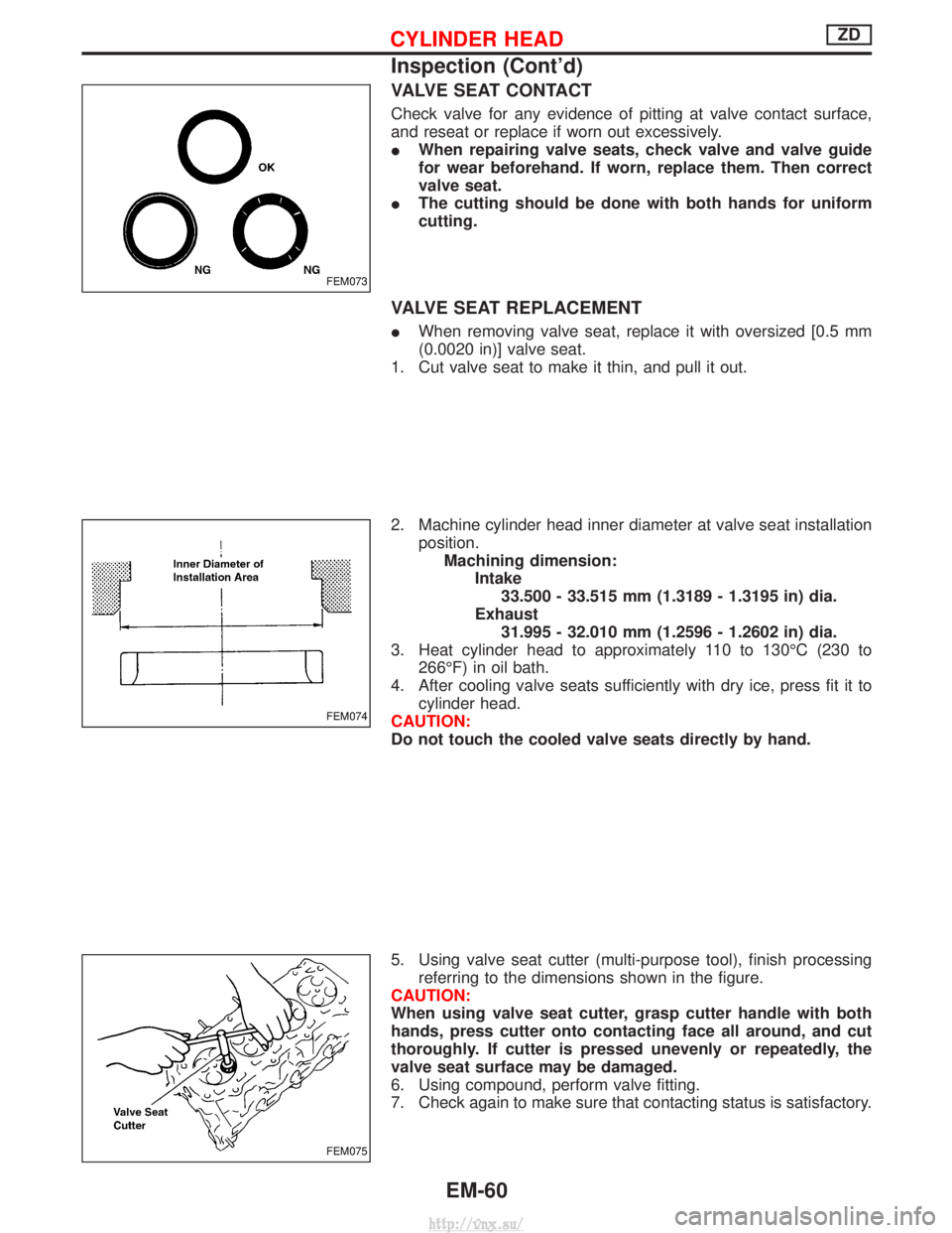
VALVE SEAT CONTACT
Check valve for any evidence of pitting at valve contact surface,
and reseat or replace if worn out excessively.
IWhen repairing valve seats, check valve and valve guide
for wear beforehand. If worn, replace them. Then correct
valve seat.
I The cutting should be done with both hands for uniform
cutting.
VALVE SEAT REPLACEMENT
IWhen removing valve seat, replace it with oversized [0.5 mm
(0.0020 in)] valve seat.
1. Cut valve seat to make it thin, and pull it out.
2. Machine cylinder head inner diameter at valve seat installation position.Machining dimension: Intake33.500 - 33.515 mm (1.3189 - 1.3195 in) dia.
Exhaust 31.995 - 32.010 mm (1.2596 - 1.2602 in) dia.
3. Heat cylinder head to approximately 110 to 130ÉC (230 to 266ÉF) in oil bath.
4. After cooling valve seats sufficiently with dry ice, press fit it to cylinder head.
CAUTION:
Do not touch the cooled valve seats directly by hand.
5. Using valve seat cutter (multi-purpose tool), finish processing referring to the dimensions shown in the figure.
CAUTION:
When using valve seat cutter, grasp cutter handle with both
hands, press cutter onto contacting face all around, and cut
thoroughly. If cutter is pressed unevenly or repeatedly, the
valve seat surface may be damaged.
6. Using compound, perform valve fitting.
7. Check again to make sure that contacting status is satisfactory.
FEM073
FEM074
FEM075
CYLINDER HEADZD
Inspection (Cont'd)
EM-60
http://vnx.su/
Page 154 of 1833
Precautions
IDo not perform operation unless it is perfectly safe.
I Do not start operation unless the exhaust system and coolant
are cooled down.
I Lift the engine at the designated support points only.
I Perform operations for the items other than the engine body,
referring to the applicable sections.
I Refer to MT section and AT section for rear mount.
Removal
IAfter removing transmission, hoist the engine and remove it.
Preparation
1. Drain coolant from radiator drain plugs.
2. Remove the following parts.
IEngine hood
I Undercover
I Under protector
I Battery
I Intercooler
I Radiator shroud
I Radiator
I Accessory belt
I Cooling fan
I Exhaust front tube
YEM032
ENGINE REMOVALZD
EM-63
http://vnx.su/
Page 194 of 1833

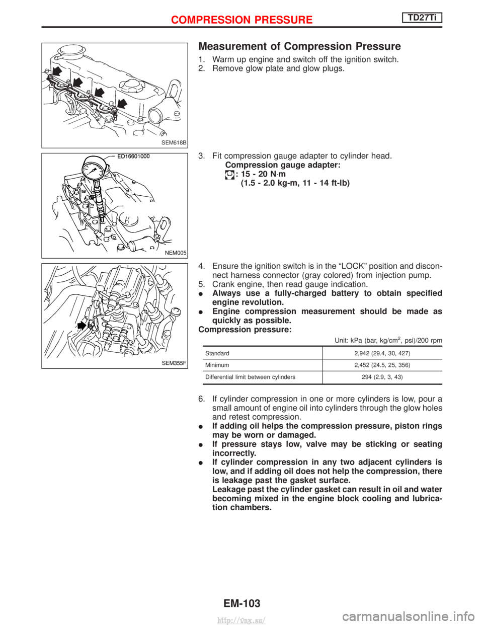
Measurement of Compression Pressure
1. Warm up engine and switch off the ignition switch.
2. Remove glow plate and glow plugs.
3. Fit compression gauge adapter to cylinder head.Compression gauge adapter:
:15-20N ×m
(1.5 - 2.0 kg-m, 11 - 14 ft-lb)
4. Ensure the ignition switch is in the ªLOCKº position and discon- nect harness connector (gray colored) from injection pump.
5. Crank engine, then read gauge indication.
I Always use a fully-charged battery to obtain specified
engine revolution.
I Engine compression measurement should be made as
quickly as possible.
Compression pressure:
Unit: kPa (bar, kg/cm2, psi)/200 rpm
Standard 2,942 (29.4, 30, 427)
Minimum 2,452 (24.5, 25, 356)
Differential limit between cylinders 294 (2.9, 3, 43)
6. If cylinder compression in one or more cylinders is low, pour a small amount of engine oil into cylinders through the glow holes
and retest compression.
I If adding oil helps the compression pressure, piston rings
may be worn or damaged.
I If pressure stays low, valve may be sticking or seating
incorrectly.
I If cylinder compression in any two adjacent cylinders is
low, and if adding oil does not help the compression, there
is leakage past the gasket surface.
Leakage past the cylinder gasket can result in oil and water
becoming mixed in the engine block cooling and lubrica-
tion chambers.
SEM618B
NEM005
SEM355F
COMPRESSION PRESSURETD27Ti
EM-103
http://vnx.su/
Page 209 of 1833
OIL SEAL INSTALLING DIRECTION
IWhen installing a new front or rear oil seal, make sure its
mounting direction is correct.
CRANKSHAFT FRONT OIL SEAL
1. Remove protecting cover.
2. Remove radiator shroud.
3. Remove cooling fan.
4. Remove drive belts.
5. Remove crank pulley.
6. Remove crankshaft oil seal.
IBe careful not to damage sealing surfaces of crankshaft.
7. Coat new oil seal with engine oil and install it in place.
CRANKSHAFT REAR OIL SEAL
1. Dismount transmission.
2. Remove clutch cover assembly.
3. Remove flywheel and rear plate.
4. Remove oil seal retainer assembly, then remove oil seal.
I Be careful not to damage sealing surfaces of crankshaft.
5. Coat new oil seal with engine oil and install it in place.
SEM715A
SEM644B
SEM217B
OIL SEAL REPLACEMENTTD27Ti
EM-118
http://vnx.su/
Page 242 of 1833

ENGINE LUBRICATION &COOLING SYSTEMS
SECTION
LC
CONTENTS
ZD
PRECAUTIONS AND PREPARATION ............................2
Liquid Gasket Application Procedure ..........................2
Special Service Tools ..................................................2
ENGINE LUBRICATION SYSTEM ..................................3
Lubricating Circuit ........................................................3
Oil Pressure Check......................................................4
Oil Pump ......................................................................5
Oil Jet........................................................................\
...7
Oil Cooler .....................................................................8
ENGINE COOLING SYSTEM ..........................................9
Cooling Circuit .............................................................9
System Check............................................................10
Water Pump ............................................................... 11
Thermostat .................................................................12
Water Outlet ...............................................................13
Radiator .....................................................................14
Cooling Fan (Crankshaft driven) ...............................15
EGR Cooler ...............................................................16
SERVICE DATA AND SPECIFICATIONS (SDS) ..........17
Engine Lubrication System ........................................17
Engine Cooling System .............................................17 TD27TiPREPARATION
..............................................................18
PRECAUTION ................................................................19
ENGINE LUBRICATION SYSTEM ................................20
Lubrication Circuit ......................................................20
Oil Pressure Check....................................................21
Oil Pump ....................................................................22
Oil Filter Bracket ........................................................24
Oil Cooler ...................................................................25
Oil Jet........................................................................\
.26
ENGINE COOLING SYSTEM ........................................27
Cooling Circuit ...........................................................27
System Inspection .....................................................28
Water Pump ...............................................................29
Thermostat .................................................................31
Radiator .....................................................................32
Cooling Fan ...............................................................33
SERVICE DATA AND SPECIFICATIONS (SDS) ..........34
Engine Lubrication System ........................................34
Engine Cooling System .............................................34
http://vnx.su/
Page 250 of 1833
Cooling Circuit
YLC064
ENGINE COOLING SYSTEMZD
LC-9
http://vnx.su/
Page 251 of 1833

System Check
WARNING:
Never remove the radiator cap when the engine is hot. Serious
burns could occur from high pressure coolant escaping from
the radiator.
Wrap a thick cloth around the cap. Slowly turn it a quarter turn
to allow built-up pressure to escape. Carefully remove the cap
by turning it all the way.
CHECKING COOLING SYSTEM HOSES
Check hoses for the following:
IImproper attachment
I Leaks
I Cracks
I Damage
I Chafing
I Deterioration
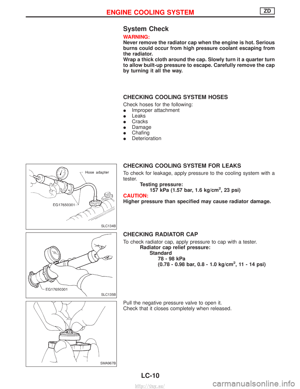
CHECKING COOLING SYSTEM FOR LEAKS
To check for leakage, apply pressure to the cooling system with a
tester.
Testing pressure:157 kPa (1.57 bar, 1.6 kg/cm
2, 23 psi)
CAUTION:
Higher pressure than specified may cause radiator damage.
CHECKING RADIATOR CAP
To check radiator cap, apply pressure to cap with a tester. Radiator cap relief pressure:Standard78-98kPa
(0.78 - 0.98 bar, 0.8 - 1.0 kg/cm
2, 11 - 14 psi)
Pull the negative pressure valve to open it.
Check that it closes completely when released.
SLC134B
SLC135B
SMA967B
ENGINE COOLING SYSTEMZD
LC-10
http://vnx.su/
Page 252 of 1833
Water Pump
CAUTION:
IWhen removing water pump assembly, be careful not to
get coolant on drive belt.
I Water pump cannot be disassembled and should be
replaced as a unit.
I Always replace with new gasket.
I After installing water pump, connect hose and clamp
securely, then check for leaks using radiator cap tester.
Refer to MA section.
REMOVAL AND INSTALLATION
1. Drain coolant from radiator and cylinder block.
Refer to MA section (ªChanging Engine Coolantº, ªENGINE
MAINTENANCEº).
2. Remove radiator upper hose.
3. Remove radiator shroud.
4. Remove cooling fan.
5. Remove drive belt. Refer to MA section, ªChecking Drive Beltº.
6. Remove insulator.
7. Remove vacuum pipe.
8. Remove TDC sensor. Refer to EM section, ªTDC sensor removal and installationº in ªTIMING GEARº.
9. Remove fan coupling with water pump.
10. Install in the reverse order of removal.
JLC373B
ENGINE COOLING SYSTEMZD
LC-11
http://vnx.su/