Page 64 of 1833

12. Fill reservoir tank up to ªMAXº level, and re-install radiator cap.
13. Run the engine at approximately 2,000 rpm for about oneminute.
14. Stop engine and cool it down, then refill the radiator and the reservoir tank up to the specified level.
Checking Cooling System
CHECKING HOSES
Check hoses for proper attachment, leaks, cracks, damage, loose
connections, chafing and deterioration.
CHECKING RADIATOR CAP
Apply pressure to radiator cap by means of a cap tester to see if it
is satisfactory. Radiator cap relief pressure:78-98kPa
(0.78 - 0.98 bar, 0.8 - 1.0 kg/cm
2, 11 - 14 psi)
CHECKING COOLING SYSTEM FOR LEAKS
Apply pressure to the cooling system by means of a tester to check
for leakage. Testing pressure:157 kPa (1.57 bar, 1.6 kg/cm
2, 23 psi)
CAUTION:
Higher than the specified pressure may cause radiator dam-
age.
Checking and Replacing fuel filter and Draining
Water
Be careful not to spill fuel in engine compartment. Place a rag
to absorb fuel.
REPLACING FUEL FILTER
1. Remove fuel filter sensor and drain fuel.
YMA008
SLC613
SMA990A
NMA009
ENGINE MAINTENANCETD
Changing Engine Coolant (Cont'd)
MA-23
http://vnx.su/
Page 73 of 1833

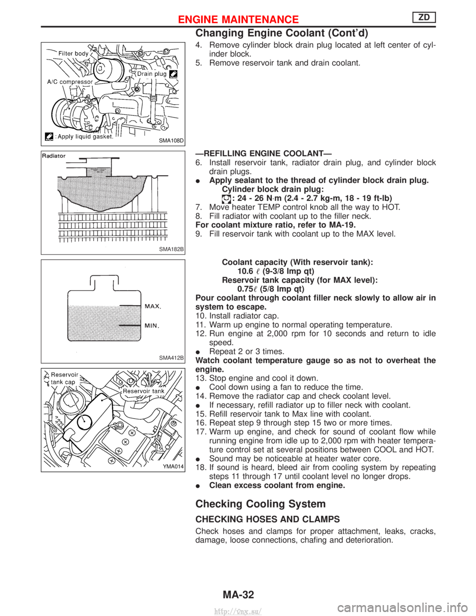
4. Remove cylinder block drain plug located at left center of cyl-inder block.
5. Remove reservoir tank and drain coolant.
ÐREFILLING ENGINE COOLANTÐ
6. Install reservoir tank, radiator drain plug, and cylinder block drain plugs.
I Apply sealant to the thread of cylinder block drain plug.
Cylinder block drain plug:
:24-26N ×m (2.4 - 2.7 kg-m, 18 - 19 ft-lb)
7. Move heater TEMP control knob all the way to HOT.
8. Fill radiator with coolant up to the filler neck.
For coolant mixture ratio, refer to MA-19.
9. Fill reservoir tank with coolant up to the MAX level.
Coolant capacity (With reservoir tank):10.6 (9-3/8 Imp qt)
Reservoir tank capacity (for MAX level): 0.75 (5/8 Imp qt)
Pour coolant through coolant filler neck slowly to allow air in
system to escape.
10. Install radiator cap.
11. Warm up engine to normal operating temperature.
12. Run engine at 2,000 rpm for 10 seconds and return to idle speed.
I Repeat 2 or 3 times.
Watch coolant temperature gauge so as not to overheat the
engine.
13. Stop engine and cool it down.
I Cool down using a fan to reduce the time.
14. Remove the radiator cap and check coolant level.
I If necessary, refill radiator up to filler neck with coolant.
15. Refill reservoir tank to Max line with coolant.
16. Repeat step 9 through step 15 two or more times.
17. Warm up engine, and check for sound of coolant flow while running engine from idle up to 2,000 rpm with heater tempera-
ture control set at several positions between COOL and HOT.
I Sound may be noticeable at heater water core.
18. If sound is heard, bleed air from cooling system by repeating steps 11 through 17 until coolant level no longer drops.
I Clean excess coolant from engine.
Checking Cooling System
CHECKING HOSES AND CLAMPS
Check hoses and clamps for proper attachment, leaks, cracks,
damage, loose connections, chafing and deterioration.
SMA108D
SMA182B
SMA412B
YMA014
ENGINE MAINTENANCEZD
Changing Engine Coolant (Cont'd)
MA-32
http://vnx.su/
Page 74 of 1833

CHECKING RADIATOR CAP
Apply pressure to radiator cap (side with pressure valve) with cap
tester to see if it is satisfactory.Radiator cap relief pressure:108 - 128 kPa
(1.08 - 1.28 bar, 1.1 - 1.3 kg/cm
2, 16 - 18 psi)
Pull the negative-pressure valve to open it. Check that it closes
completely when released.
CHECKING COOLING SYSTEM FOR LEAKS
Apply pressure to the cooling system with cap tester to check for
leakage. Testing pressure:157 kPa (1.57 bar, 1.6 kg/cm
2, 23 psi)
CAUTION:
Use of higher pressure than the specified value may cause
damage to radiator.
Checking and Replacing Fuel Filter and
Draining Water
Be careful not to spill fuel in engine compartment. Place a rag
to absorb fuel.
CHECKING FUEL FILTER
Check fuel filter for fuel leakage, damage and other abnormal
signs.
REPLACING FUEL FILTER
1. Disconnect harness connector and drain fuel.
2. Remove fuel filter using band-type filter wrench.
3. Remove fuel filter and fuel filter sensor.
CAUTION:
Remove fuel filter without spilling fuel. If spilt, wipe off imme-
diately. Be specially careful not to spill fuel on engine mount
insulator.
SLC613
SMA871B
JMA110D
DMA011
SMA111D
ENGINE MAINTENANCEZD
Checking Cooling System (Cont'd)
MA-33
http://vnx.su/
Page 85 of 1833
Checking Fluid Level and Leaks (Power
steering)
Check fluid level.
Fluid level can be checked when the fluid is either hot or cold.
CAUTION:
IDo not overfill.
I Recommended fluid is Automatic Transmission Fluid
ªDEXRON
TMº type.
I Check lines for improper attachment, leaks, cracks, damage,
loose connections, chafing and deterioration.
Greasing Steering Linkage
Apply multi-purpose grease to point shown in the illustration.
Ventilation Air Filter
FUNCTION
Air inside passenger compartment is kept clean at either recircula-
tion or fresh mode by installing ventilation air filter into cooling unit.
REPLACEMENT PROCEDURES
IRemove glove box.
Refer to BT section.
I Take out ventilation air filter which is secured with one screw,
from cooling unit.
I Replace with new one and reinstall glove box.
NMA058
SST621A
EMA053
RHA336F
NMA070
CHASSIS AND BODY MAINTENANCE
MA-44
http://vnx.su/
Page 89 of 1833

Engine Maintenance
INSPECTION AND ADJUSTMENT
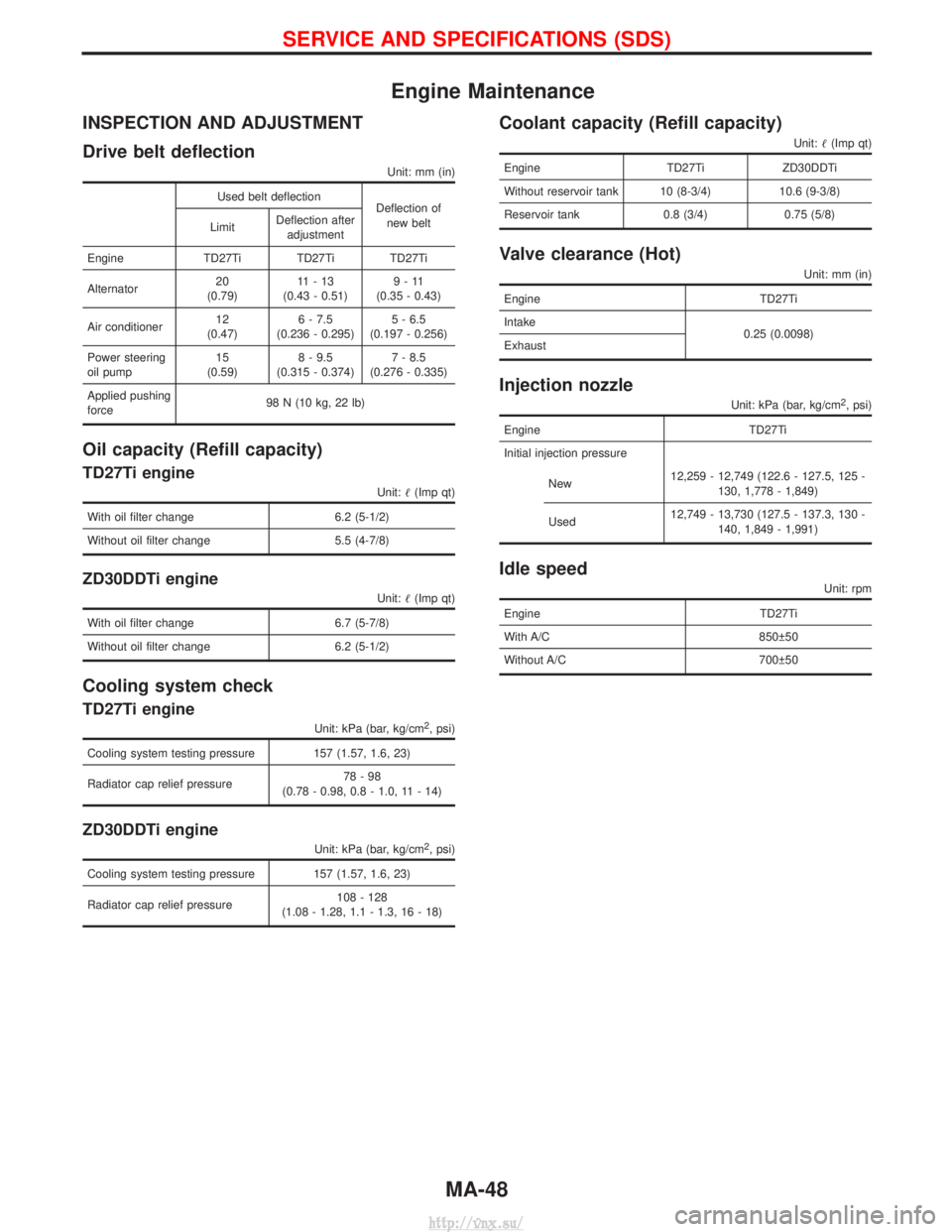
Drive belt deflection
Unit: mm (in)
Used belt deflectionDeflection of
new belt
Limit Deflection after
adjustment
Engine TD27Ti TD27Ti TD27Ti
Alternator 20
(0.79) 11-13
(0.43 - 0.51) 9-11
(0.35 - 0.43)
Air conditioner 12
(0.47) 6 - 7.5
(0.236 - 0.295) 5 - 6.5
(0.197 - 0.256)
Power steering
oil pump 15
(0.59) 8 - 9.5
(0.315 - 0.374) 7 - 8.5
(0.276 - 0.335)
Applied pushing
force 98 N (10 kg, 22 lb)
Oil capacity (Refill capacity)
TD27Ti engine
Unit:
(Imp qt)
With oil filter change 6.2 (5-1/2)
Without oil filter change 5.5 (4-7/8)
ZD30DDTi engine
Unit: (Imp qt)
With oil filter change 6.7 (5-7/8)
Without oil filter change 6.2 (5-1/2)
Cooling system check
TD27Ti engine
Unit: kPa (bar, kg/cm2, psi)
Cooling system testing pressure 157 (1.57, 1.6, 23)
Radiator cap relief pressure 78-98
(0.78 - 0.98, 0.8 - 1.0, 11 - 14)
ZD30DDTi engine
Unit: kPa (bar, kg/cm2, psi)
Cooling system testing pressure 157 (1.57, 1.6, 23)
Radiator cap relief pressure 108 - 128
(1.08 - 1.28, 1.1 - 1.3, 16 - 18)
Coolant capacity (Refill capacity)
Unit: (Imp qt)
Engine TD27TiZD30DDTi
Without reservoir tank 10 (8-3/4) 10.6 (9-3/8)
Reservoir tank 0.8 (3/4) 0.75 (5/8)
Valve clearance (Hot)
Unit: mm (in)
Engine TD27Ti
Intake 0.25 (0.0098)
Exhaust
Injection nozzle
Unit: kPa (bar, kg/cm2, psi)
Engine TD27Ti
Initial injection pressure
New 12,259 - 12,749 (122.6 - 127.5, 125 -
130, 1,778 - 1,849)
Used 12,749 - 13,730 (127.5 - 137.3, 130 -
140, 1,849 - 1,991)
Idle speed
Unit: rpm
Engine TD27Ti
With A/C 850 50
Without A/C 700 50
SERVICE AND SPECIFICATIONS (SDS)
MA-48
http://vnx.su/
Page 100 of 1833

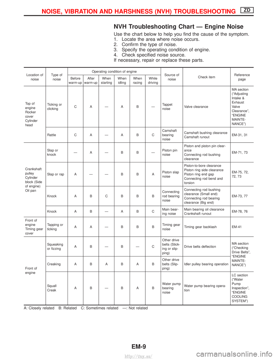
NVH Troubleshooting Chart Ð Engine Noise
Use the chart below to help you find the cause of the symptom.
1. Locate the area where noise occurs.
2. Confirm the type of noise.
3. Specify the operating condition of engine.
4. Check specified noise source.
If necessary, repair or replace these parts.
Location ofnoise Type of
noise Operating condition of engine
Source of
noise Check item Reference
page
Before
warm-up After
warm-up When
starting When
idling When
racing While
driving
To p o f
engine
Rocker
cover
Cylinder
head Ticking or
clicking
C AÐA BÐ Tappet
noiseValve clearance MA section
(ªAdjusting
Intake &
Exhaust
Valve
Clearanceº,
ªENGINE
MAINTE-
NANCEº)
Rattle C A Ð A B C Camshaft
bearing
noiseCamshaft bushing clearance
Camshaft runout
EM-31, 31
Crankshaft
pulley
Cylinder
block (Side
of engine)
Oil pan Slap or
knock
ÐAÐB BÐ Piston pin
noisePiston and piston pin clear-
ance
Connecting rod bushing
clearance
EM-71, 73
Slap or rap A Ð Ð B B A Piston slap
noisePiston-to-bore clearance
Piston ring side clearance
Piston ring end gap
Connecting rod bend and
torsion EM-75, 72,
72, 73
Knock A B C B B B Connecting
rod bearing
noiseConnecting rod bushing
clearance (Small end)
Connecting rod bearing
clearance (Big end)
EM-73, 77
Knock A B Ð A B C Main bear-
ing noiseMain bearing oil clearance
Crankshaft runout
EM-78, 76
Front of
engine
Timing gear
cover Tapping or
ticking
AAÐBBB Timing gear
noiseTiming gear backlash EM-41
Front of
engine Squeaking
or fizzing
A BÐBÐC Other drive
belts (Stick-
ing or slip-
ping)Drive belts deflection
MA section
(ªChecking
Drive Beltsº,
ªENGINE
MAINTE-
NANCEº)
Creaking
ABABAB Other drive
belts (Slip-
ping)Idler pulley bearing operation
Squall
Creak ABÐBAB Water pump
bearing
noiseWater pump bearing opera-
tion LC section
(ªWater
Pump
Inspectionº,
ªENGINE
COOLING
SYSTEMº)
A: Closely related B: Related C: Sometimes related Ð: Not related
NOISE, VIBRATION AND HARSHNESS (NVH) TROUBLESHOOTINGZD
EM-9
http://vnx.su/
Page 115 of 1833
Removal and Installation
REMOVAL
1. Remove the following parts.
IRadiator under side
I Radiator shroud
I Cooling fan
I Chain cover front side
I A/T cooler hose (Disconnect)
I Vacuum hose
I Intercooler cover (When removing vacuum tank)
2. Remove the installation bolts and pull the vacuum pump from the engine front directly.
3. If it is difficult to remove from the spline shaft connection, tap lightly with a plastic hammer.
SEM320G
SEM321G
VACUUM PUMPZD
EM-24
http://vnx.su/
Page 117 of 1833
Removal and Installation
CAUTION:
As the internal mechanism of the idler gear must first of all,
and always, be set by a bolt when removing the timing chain
before removing the fuel injection pump and timing gear, fol-
low the procedures on EM-38, ªRemoval of timing chain after
setting idler gearº, ªElectronic controlled fuel injection pumpº.
IThis chapter will deal with the summary of removing the timing
chain before removing the camshaft and cylinder head.
Removal
1. Remove the following parts.
IEngine cover
I Intercooler
I Air inlet pipe
I Throttle body
I Rocker cover
I Spill tube
I Coolant (Drain)
I Radiator upper hose
I Water outlet
I Radiator shroud
I Cooling fan
I Auxiliary belt
I Vacuum pipe
I Vacuum pump
YEM028
TIMING CHAINZD
EM-26
http://vnx.su/