Page 942 of 1833
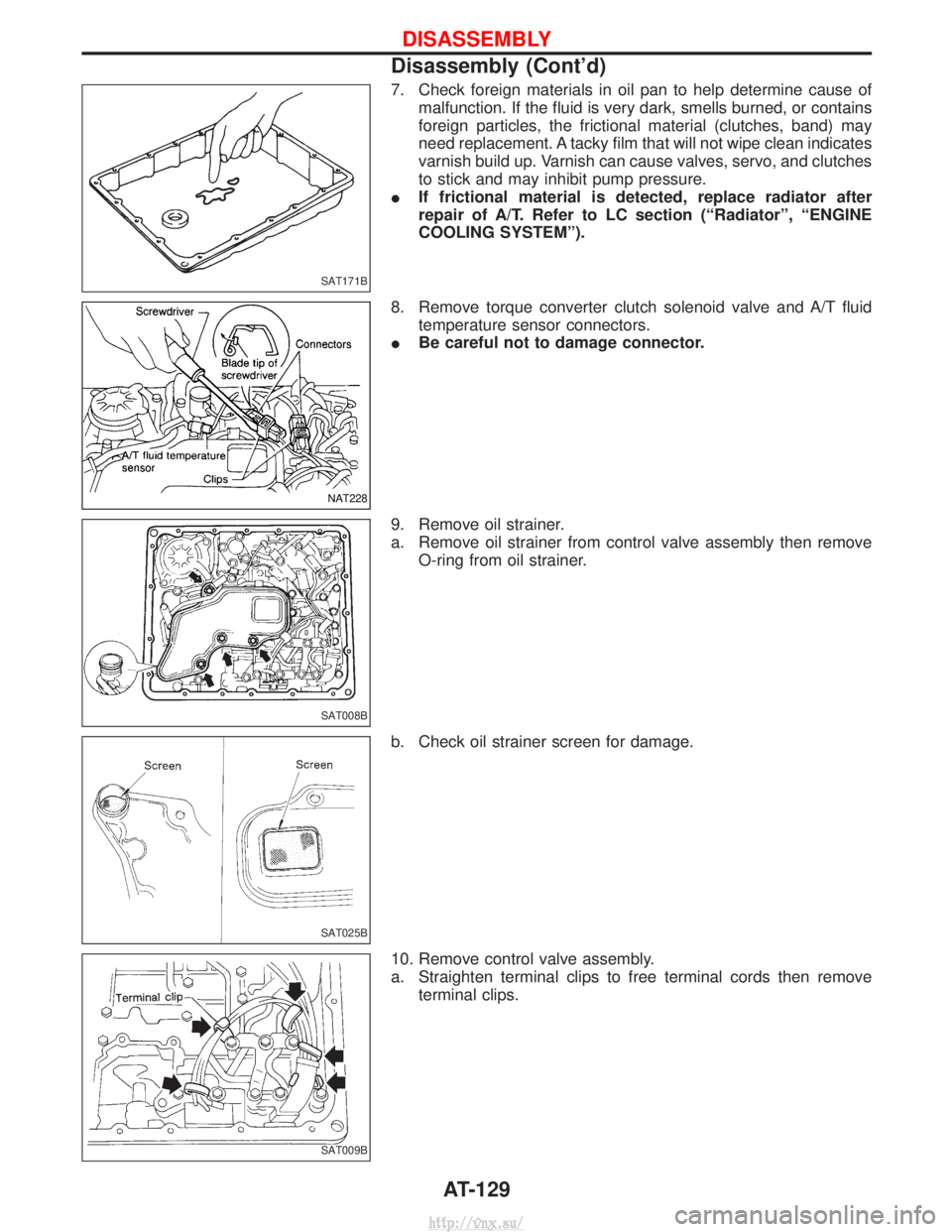
7. Check foreign materials in oil pan to help determine cause ofmalfunction. If the fluid is very dark, smells burned, or contains
foreign particles, the frictional material (clutches, band) may
need replacement. A tacky film that will not wipe clean indicates
varnish build up. Varnish can cause valves, servo, and clutches
to stick and may inhibit pump pressure.
I If frictional material is detected, replace radiator after
repair of A/T. Refer to LC section (ªRadiatorº, ªENGINE
COOLING SYSTEMº).
8. Remove torque converter clutch solenoid valve and A/T fluid temperature sensor connectors.
I Be careful not to damage connector.
9. Remove oil strainer.
a. Remove oil strainer from control valve assembly then remove O-ring from oil strainer.
b. Check oil strainer screen for damage.
10. Remove control valve assembly.
a. Straighten terminal clips to free terminal cords then remove terminal clips.
SAT171B
NAT228
SAT008B
SAT025B
SAT009B
DISASSEMBLY
Disassembly (Cont'd)
AT-129
http://vnx.su/
Page 1404 of 1833
Control Operation
FAN CONTROL DIAL
This DIAL turns the fan ON and OFF, and controls fan speed.
AIR CONTROL DIAL
This DIAL allows outlet air to flow.
TEMPERATURE CONTROL DIAL
This DIAL allows the temperature of the outlet air to be adjusted.
AIR RECIRCULATION SWITCH
OFF position:
Outside air is drawn into the passenger compartment.
ON position (Indicator light ON):
Interior air is recirculated inside the vehicle.
AIR CONDITIONER SWITCH
Start the engine, turn the fan control dial to the desired (1 to 4) position and press the air conditioner switch
to turn ON the air conditioner. The indicator light will come on when the air conditioner is ON. To stop the air
conditioner, push the switch again to return it to the original position.
The air conditioner cooling function operates only when the engine is running.
NHA331
DESCRIPTION Ð Overall System
HA-7
http://vnx.su/
Page 1414 of 1833
Set the recovery/recycling/rechargingequipment.
Recovered lubrication oilRefer to LUBRICATION
OIL Ð Checking and
Adjusting. Discharge refrigerant into recovery/
recycling/recharging equipment.
Repair or replace parts.
Evacuate the unwanted air in charging hoses.
Evacuating (over 25 minutes).
Check air tightness.ERepair.
G
ECharging [approx. 200 g (7.05 oz)].
*-1
Preliminary refrigerant leak check.
Complete charging
[specified amount Ð 200 g (7.05 oz)].
*-1
Check for refrigerant leaks.
*-2
Check for A/C operation and A/C cooling performance
Remove service couplers from A/C service valves.
Recover refrigerant in charging hoses.
Note: *-1 Before charging refrigerant, ensure engine is off.*-2 Before checking for leaks, start engine to activate air conditioning system then turn it off.
Service valve caps must be attached to valves (to prevent leak).
H
H
H
H
H
H
H
H
H
H
H
H
SERVICE PROCEDURES
HFC-134a (R-134a) Service Procedure (Cont'd)
HA-17
http://vnx.su/
Page 1420 of 1833
Lubrication Oil
Name: Nissan A/C System Oil Type S
Part number: KLH00-PAGS0
Maintenance of Oil Quantity in Compressor
The oil used to lubricate the compressor circulates through the
system with the refrigerant. Whenever any component of the sys-
tem is replaced or a large amount of gas leakage occurs, add oil
to the compressor to maintain the specified amount.
If oil quantity is not maintained properly, the following malfunctions
may result:
ILack of oil: May lead to a seized compressor
I Excessive oil: Inadequate cooling (thermal exchange impeded)
Checking and Adjusting
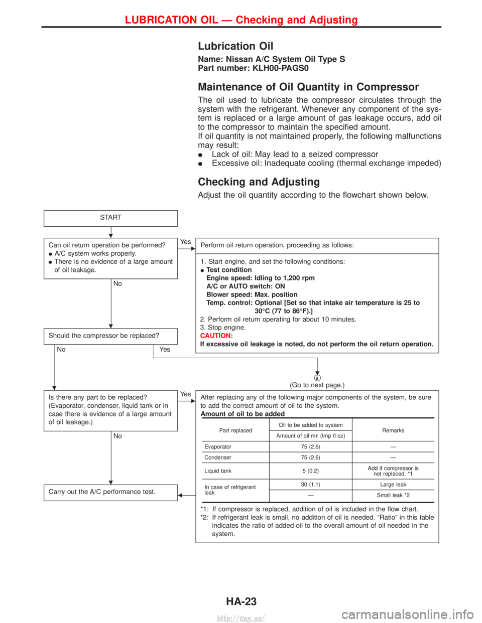
Adjust the oil quantity according to the flowchart shown below.
START
Can oil return operation be performed?
IA/C system works properly.
I There is no evidence of a large amount
of oil leakage.
No
EYe s
Perform oil return operation, proceeding as follows:
------------------------------------------------------------------------------------------------------------------------------------------------------------------------------------------------------------------------------------------------------------------------------------------------------------------------------------------------------------------------------------------------------------------------------------------------------------------------------------------------------------------------------------------------------------- 1. Start engine, and set the following conditions:
I Test condition
Engine speed: Idling to 1,200 rpm
A/C or AUTO switch: ON
Blower speed: Max. position
Temp. control: Optional [Set so that intake air temperature is 25 to
30ÉC (77 to 86ÉF).]
2. Perform oil return operating for about 10 minutes.
3. Stop engine.
CAUTION:
If excessive oil leakage is noted, do not perform the oil return operation.
Should the compressor be replaced?
No Yes
qA(Go to next page.)
Is there any part to be replaced?
(Evaporator, condenser, liquid tank or in
case there is evidence of a large amount
of oil leakage.)
No
EYe s After replacing any of the following major components of the system, be sure
to add the correct amount of oil to the system.
Amount of oil to be added
*1: If compressor is replaced, addition of oil is included in the flow chart.
*2: If refrigerant leak is small, no addition of oil is needed. ªRatioº in this table indicates the ratio of added oil to the overall amount of oil needed in the
system.
Carry out the A/C performance test.F
Part replaced Oil to be added to system
Remarks
Amount of oil m (Imp fl oz)
Evaporator 75 (2.6)Ð
Condenser 75 (2.6)Ð
Liquid tank 5 (0.2)Add if compressor is
not replaced. *1
In case of refrigerant
leak 30 (1.1)
Large leak
Ð Small leak *2
H
H
H
H
H
LUBRICATION OIL Ð Checking and Adjusting
HA-23
http://vnx.su/
Page 1429 of 1833
Performance Test Diagnoses
INSUFFICIENT COOLING
MHA176B
DIAGNOSES Ð Overall System
HA-32
http://vnx.su/
Page 1430 of 1833
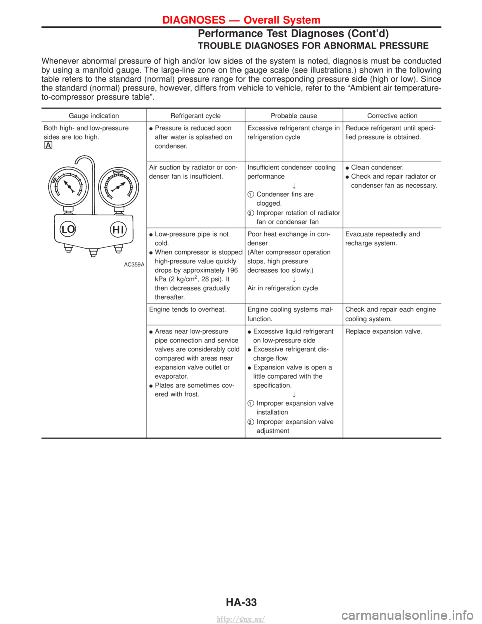
TROUBLE DIAGNOSES FOR ABNORMAL PRESSURE
Whenever abnormal pressure of high and/or low sides of the system is noted, diagnosis must be conducted
by using a manifold gauge. The large-line zone on the gauge scale (see illustrations.) shown in the following
table refers to the standard (normal) pressure range for the corresponding pressure side (high or low). Since
the standard (normal) pressure, however, differs from vehicle to vehicle, refer to the ªAmbient air temperature-
to-compressor pressure tableº.
Gauge indicationRefrigerant cycleProbable causeCorrective action
Both high- and low-pressure
sides are too high.
AC359A
I Pressure is reduced soon
after water is splashed on
condenser. Excessive refrigerant charge in
refrigeration cycle
Reduce refrigerant until speci-
fied pressure is obtained.
Air suction by radiator or con-
denser fan is insufficient. Insufficient condenser cooling
performance
"
q
1Condenser fins are
clogged.
q
2Improper rotation of radiator
fan or condenser fan I
Clean condenser.
I Check and repair radiator or
condenser fan as necessary.
I Low-pressure pipe is not
cold.
I When compressor is stopped
high-pressure value quickly
drops by approximately 196
kPa (2 kg/cm
2, 28 psi). It
then decreases gradually
thereafter. Poor heat exchange in con-
denser
(After compressor operation
stops, high pressure
decreases too slowly.)
"
Air in refrigeration cycle Evacuate repeatedly and
recharge system.
Engine tends to overheat. Engine cooling systems mal- function.Check and repair each engine
cooling system.
I Areas near low-pressure
pipe connection and service
valves are considerably cold
compared with areas near
expansion valve outlet or
evaporator.
I Plates are sometimes cov-
ered with frost. I
Excessive liquid refrigerant
on low-pressure side
I Excessive refrigerant dis-
charge flow
I Expansion valve is open a
little compared with the
specification.
"
q
1Improper expansion valve
installation
q
2Improper expansion valve
adjustment Replace expansion valve.
DIAGNOSES Ð Overall System
Performance Test Diagnoses (Cont'd)
HA-33
http://vnx.su/
Page 1459 of 1833
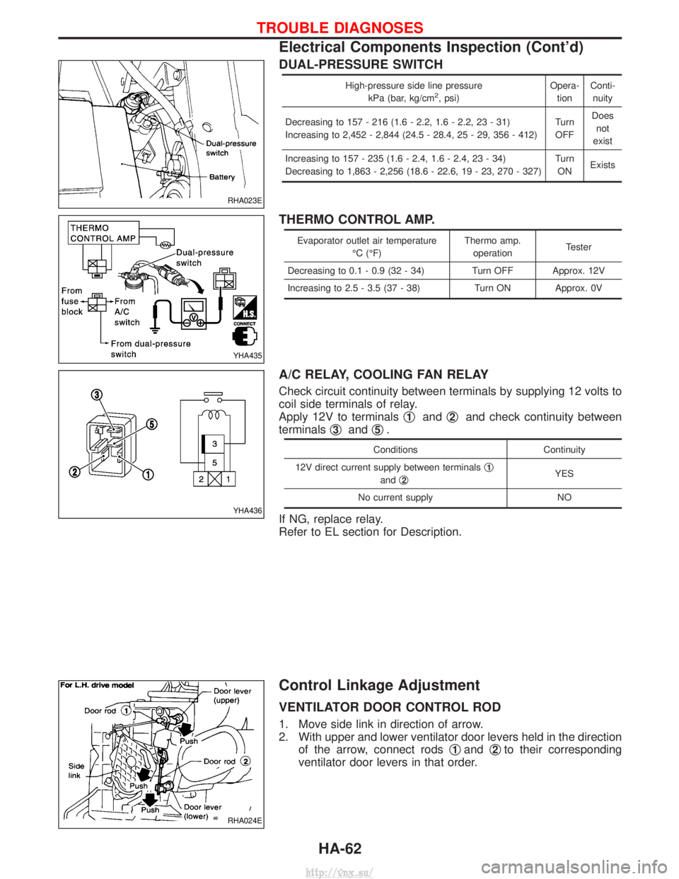
DUAL-PRESSURE SWITCH
High-pressure side line pressurekPa (bar, kg/cm2, psi) Opera-
tion Conti-
nuity
Decreasing to 157 - 216 (1.6 - 2.2, 1.6 - 2.2, 23 - 31)
Increasing to 2,452 - 2,844 (24.5 - 28.4, 25 - 29, 356 - 412) Turn
OFF Does
not
exist
Increasing to 157 - 235 (1.6 - 2.4, 1.6 - 2.4, 23 - 34)
Decreasing to 1,863 - 2,256 (18.6 - 22.6, 19 - 23, 270 - 327) Turn
ON Exists
THERMO CONTROL AMP.
Evaporator outlet air temperature
ÉC (ÉF) Thermo amp.
operation Tester
Decreasing to 0.1 - 0.9 (32 - 34) Turn OFF Approx. 12V
Increasing to 2.5 - 3.5 (37 - 38) Turn ON Approx. 0V
A/C RELAY, COOLING FAN RELAY
Check circuit continuity between terminals by supplying 12 volts to
coil side terminals of relay.
Apply 12V to terminals q
1andq2and check continuity between
terminals q
3andq5.
Conditions
Continuity
12V direct current supply between terminals q
1
andq2YES
No current supply NO
If NG, replace relay.
Refer to EL section for Description.
Control Linkage Adjustment
VENTILATOR DOOR CONTROL ROD
1. Move side link in direction of arrow.
2. With upper and lower ventilator door levers held in the direction of the arrow, connect rods q
1andq2to their corresponding
ventilator door levers in that order.
RHA023E
YHA435
YHA436
RHA024E
TROUBLE DIAGNOSES
Electrical Components Inspection (Cont'd)
HA-62
http://vnx.su/
Page 1513 of 1833
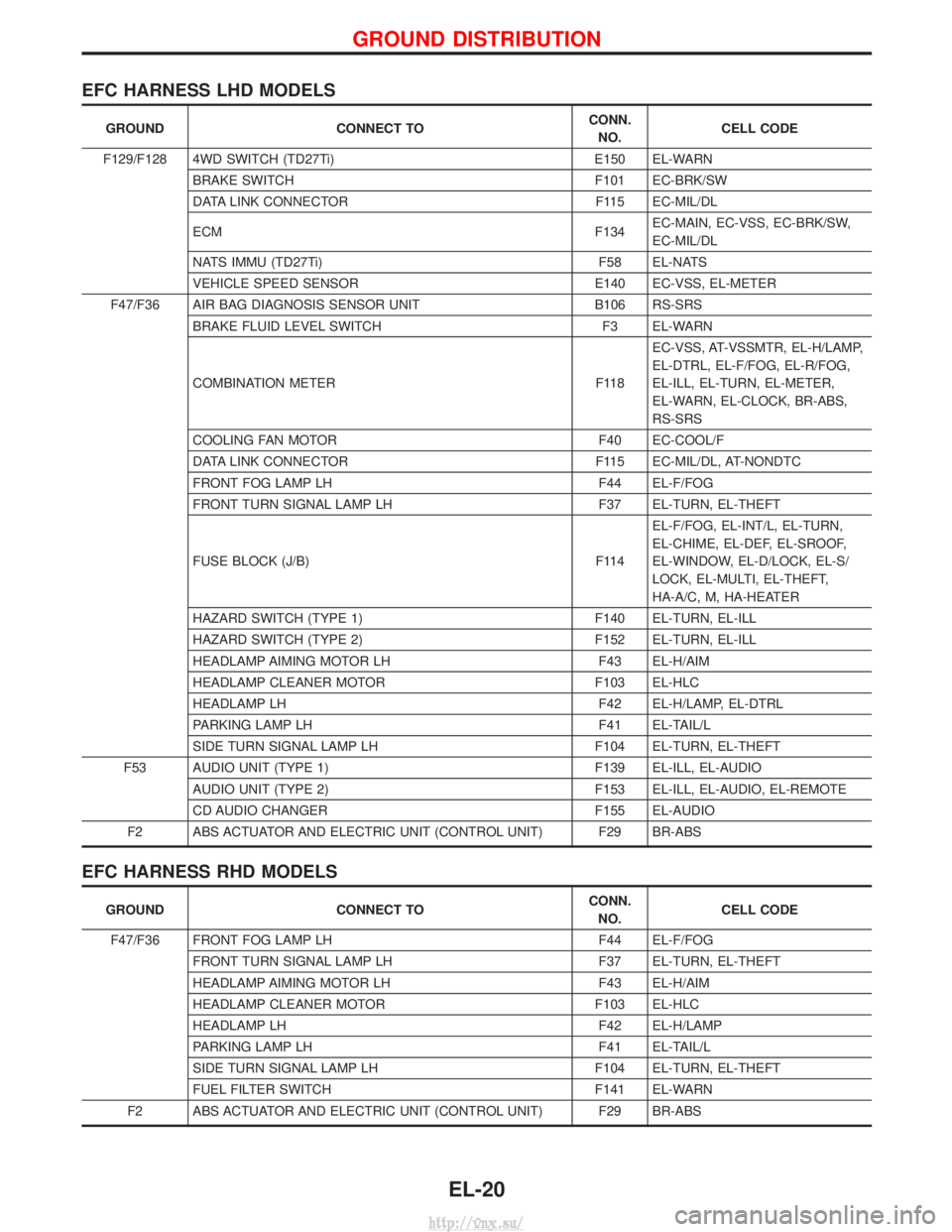
EFC HARNESS LHD MODELS
GROUNDCONNECT TO CONN.
NO. CELL CODE
F129/F128 4WD SWITCH (TD27Ti) E150 EL-WARN
BRAKE SWITCH F101 EC-BRK/SW
DATA LINK CONNECTOR F115 EC-MIL/DL
ECM F134EC-MAIN, EC-VSS, EC-BRK/SW,
EC-MIL/DL
NATS IMMU (TD27Ti) F58 EL-NATS
VEHICLE SPEED SENSOR E140 EC-VSS, EL-METER
F47/F36 AIR BAG DIAGNOSIS SENSOR UNIT B106 RS-SRS
BRAKE FLUID LEVEL SWITCH F3 EL-WARN
COMBINATION METER F118EC-VSS, AT-VSSMTR, EL-H/LAMP,
EL-DTRL, EL-F/FOG, EL-R/FOG,
EL-ILL, EL-TURN, EL-METER,
EL-WARN, EL-CLOCK, BR-ABS,
RS-SRS
COOLING FAN MOTOR F40 EC-COOL/F
DATA LINK CONNECTOR F115 EC-MIL/DL, AT-NONDTC
FRONT FOG LAMP LH F44 EL-F/FOG
FRONT TURN SIGNAL LAMP LH F37 EL-TURN, EL-THEFT
FUSE BLOCK (J/B) F114EL-F/FOG, EL-INT/L, EL-TURN,
EL-CHIME, EL-DEF, EL-SROOF,
EL-WINDOW, EL-D/LOCK, EL-S/
LOCK, EL-MULTI, EL-THEFT,
HA-A/C, M, HA-HEATER
HAZARD SWITCH (TYPE 1) F140 EL-TURN, EL-ILL
HAZARD SWITCH (TYPE 2) F152 EL-TURN, EL-ILL
HEADLAMP AIMING MOTOR LH F43 EL-H/AIM
HEADLAMP CLEANER MOTOR F103 EL-HLC
HEADLAMP LH F42 EL-H/LAMP, EL-DTRL
PARKING LAMP LH F41 EL-TAIL/L
SIDE TURN SIGNAL LAMP LH F104 EL-TURN, EL-THEFT
F53 AUDIO UNIT (TYPE 1) F139 EL-ILL, EL-AUDIO
AUDIO UNIT (TYPE 2) F153 EL-ILL, EL-AUDIO, EL-REMOTE
CD AUDIO CHANGER F155 EL-AUDIO
F2 ABS ACTUATOR AND ELECTRIC UNIT (CONTROL UNIT) F29 BR-ABS
EFC HARNESS RHD MODELS
GROUND CONNECT TO CONN.
NO. CELL CODE
F47/F36 FRONT FOG LAMP LH F44 EL-F/FOG
FRONT TURN SIGNAL LAMP LH F37 EL-TURN, EL-THEFT
HEADLAMP AIMING MOTOR LH F43 EL-H/AIM
HEADLAMP CLEANER MOTOR F103 EL-HLC
HEADLAMP LH F42 EL-H/LAMP
PARKING LAMP LH F41 EL-TAIL/L
SIDE TURN SIGNAL LAMP LH F104 EL-TURN, EL-THEFT
FUEL FILTER SWITCH F141 EL-WARN
F2 ABS ACTUATOR AND ELECTRIC UNIT (CONTROL UNIT) F29 BR-ABS
GROUND DISTRIBUTION
EL-20
http://vnx.su/