2004 NISSAN TERRANO warning
[x] Cancel search: warningPage 386 of 1833
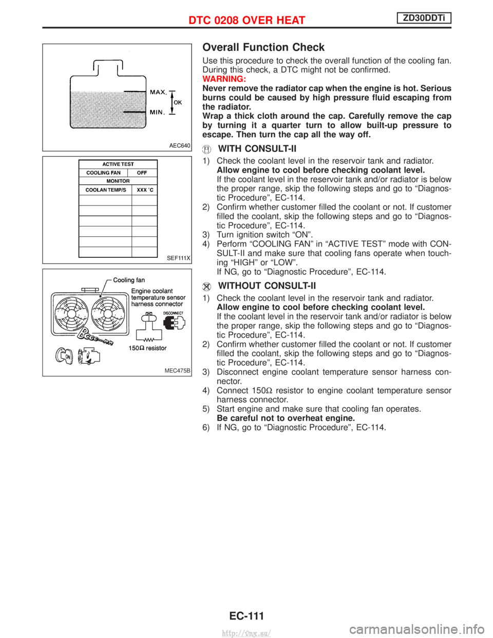
Overall Function Check
Use this procedure to check the overall function of the cooling fan.
During this check, a DTC might not be confirmed.
WARNING:
Never remove the radiator cap when the engine is hot. Serious
burns could be caused by high pressure fluid escaping from
the radiator.
Wrap a thick cloth around the cap. Carefully remove the cap
by turning it a quarter turn to allow built-up pressure to
escape. Then turn the cap all the way off.
WITH CONSULT-II
1) Check the coolant level in the reservoir tank and radiator.Allow engine to cool before checking coolant level.
If the coolant level in the reservoir tank and/or radiator is below
the proper range, skip the following steps and go to ªDiagnos-
tic Procedureº, EC-114.
2) Confirm whether customer filled the coolant or not. If customer filled the coolant, skip the following steps and go to ªDiagnos-
tic Procedureº, EC-114.
3) Turn ignition switch ªONº.
4) Perform ªCOOLING FANº in ªACTIVE TESTº mode with CON- SULT-II and make sure that cooling fans operate when touch-
ing ªHIGHº or ªLOWº.
If NG, go to ªDiagnostic Procedureº, EC-114.
WITHOUT CONSULT-II
1) Check the coolant level in the reservoir tank and radiator.Allow engine to cool before checking coolant level.
If the coolant level in the reservoir tank and/or radiator is below
the proper range, skip the following steps and go to ªDiagnos-
tic Procedureº, EC-114.
2) Confirm whether customer filled the coolant or not. If customer filled the coolant, skip the following steps and go to ªDiagnos-
tic Procedureº, EC-114.
3) Disconnect engine coolant temperature sensor harness con- nector.
4) Connect 150W resistor to engine coolant temperature sensor
harness connector.
5) Start engine and make sure that cooling fan operates. Be careful not to overheat engine.
6) If NG, go to ªDiagnostic Procedureº, EC-114.
AEC640
SEF111X
MEC475B
DTC 0208 OVER HEATZD30DDTi
EC-111
http://vnx.su/
Page 519 of 1833

Description
SYSTEM DESCRIPTION
Sensor Input Signal to ECMECM
Function Actuator
Crankshaft position
sensor (TDC) Engine speed
Glow
control Glow lamp,
Glow relay "
Glow plugs
Engine coolant tem-
perature sensor Engine coolant tem-
perature
When engine coolant temperature is more than approximately 75ÉC
(167ÉF), the glow relay turns off, inactivating the quick-glow control
until coolant temperature drops below approximately 55ÉC (131ÉF).
When coolant temperature is lower than approximately 75ÉC
(167ÉF):
I
Ignition switch ON
After ignition switch has turned to ON, the glow relay turns ON
for a certain period of time in relation to engine coolant
temperature, allowing current to flow through glow plug.
I Cranking
The glow relay turns ON, allowing current to flow through glow
plug.
I Starting
After engine has started, current continues to flow through glow
plug (after-glow mode) for a certain period in relation to engine
coolant temperature.
When engine speed exceeds approximately 4,800 rpm, current
flow through glow plug is interrupted.
The glow indicator lamp turns ON for a certain period of time in
relation to engine coolant temperature at the time glow relay is
turned ON.
COMPONENT DESCRIPTION
Glow plug
I The glow plug is provided with a ceramic heating element to
obtain a high-temperature resistance. It glows in response to a
signal sent from the ECM, allowing current to flow through the
glow plug via the glow relay.
I This engine uses two types of glow plugs.
Type A has a blue or yellow paint mark.
Type B has no paint mark.
The location of the paint mark is shown in the figure.
WARNING:
Do not use two types of glow plugs at the same time.
SEF376Y
SEF280Z
GLOW CONTROL SYSTEMZD30DDTi
EC-244
http://vnx.su/
Page 572 of 1833
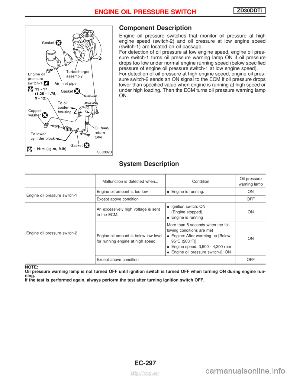
Component Description
Engine oil pressure switches that monitor oil pressure at high
engine speed (switch-2) and oil pressure at low engine speed
(switch-1) are located on oil passage.
For detection of oil pressure at low engine speed, engine oil pres-
sure switch-1 turns oil pressure warning lamp ON if oil pressure
drops too low under normal engine running speed (below specified
pressure of engine oil pressure switch-1 at low engine speed).
For detection of oil pressure at high engine speed, engine oil pres-
sure switch-2 sends an ON signal to the ECM if oil pressure drops
lower than specified value when engine is running at high speed or
under high loading. Then the ECM turns oil pressure warning lamp
ON.
System Description
Malfunction is detected when...ConditionOil pressure
warning lamp
Engine oil pressure switch-1 Engine oil amount is too low.
IEngine is running. ON
Except above condition OFF
Engine oil pressure switch-2 An excessively high voltage is sent
to the ECM.
I
Ignition switch: ON
(Engine stopped)
I Engine is running ON
Engine oil amount is below low level
for running engine at high speed. More than 5 seconds when the fol-
lowing conditions are met
I
Engine: After warming-up [Below
95ÉC (203ÉF)]
I Engine speed: 3,600 - 4,200 rpm
I Engine oil pressure switch-2: ON ON
Except above condition OFF
NOTE:
Oil pressure warning lamp is not turned OFF until ignition switch is turned OFF when turning ON during engine run-
ning.
If the test is performed again, always perform the test after turning ignition switch OFF.
SEC382D
ENGINE OIL PRESSURE SWITCHZD30DDTi
EC-297
http://vnx.su/
Page 573 of 1833
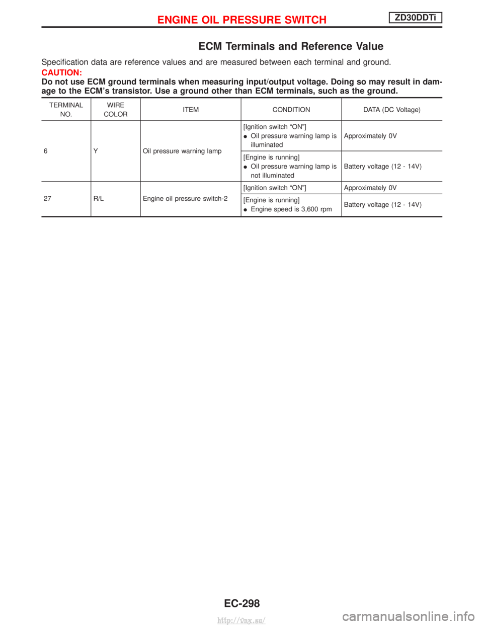
ECM Terminals and Reference Value
Specification data are reference values and are measured between each terminal and ground.
CAUTION:
Do not use ECM ground terminals when measuring input/output voltage. Doing so may result in dam-
age to the ECM's transistor. Use a ground other than ECM terminals, such as the ground.
TERMINALNO. WIRE
COLOR ITEM CONDITION DATA (DC Voltage)
6 Y Oil pressure warning lamp [Ignition switch ªONº]
I
Oil pressure warning lamp is
illuminated Approximately 0V
[Engine is running]
I Oil pressure warning lamp is
not illuminated Battery voltage (12 - 14V)
27 R/L Engine oil pressure switch-2 [Ignition switch ªONº] Approximately 0V
[Engine is running]
I
Engine speed is 3,600 rpm Battery voltage (12 - 14V)
ENGINE OIL PRESSURE SWITCHZD30DDTi
EC-298
http://vnx.su/
Page 576 of 1833
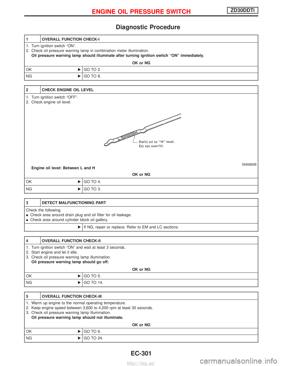
Diagnostic Procedure
1 OVERALL FUNCTION CHECK-I
1. Turn ignition switch ªONº.
2. Check oil pressure warning lamp in combination meter illumination.Oil pressure warning lamp should illuminate after turning ignition switch ªONº immediately.
OK or NG
OK EGO TO 2.
NG EGO TO 8.
2 CHECK ENGINE OIL LEVEL
1. Turn ignition switch ªOFFº.
2. Check engine oil level.
SMA885BEngine oil level: Between L and H
OK or NG
OK EGO TO 4.
NG EGO TO 3.
3 DETECT MALFUNCTIONING PART
Check the following.
ICheck area around drain plug and oil filter for oil leakage.
I Check area around cylinder block oil gallery.
EIf NG, repair or replace. Refer to EM and LC sections.
4 OVERALL FUNCTION CHECK-II
1. Turn ignition switch ªONº and wait at least 3 seconds.
2. Start engine and let it idle.
3. Check oil pressure warning lamp illumination.
Oil pressure warning lamp should go off.
OK or NG
OK EGO TO 5.
NG EGO TO 14.
5 OVERALL FUNCTION CHECK-III
1. Warm up engine to the normal operating temperature.
2. Keep engine speed between 3,600 to 4,200 rpm at least 30 seconds.
3. Check oil pressure warning lamp illumination.
Oil pressure warning lamp should not illuminate.
OK or NG
OK EGO TO 6.
NG EGO TO 24.
ENGINE OIL PRESSURE SWITCHZD30DDTi
EC-301
http://vnx.su/
Page 579 of 1833
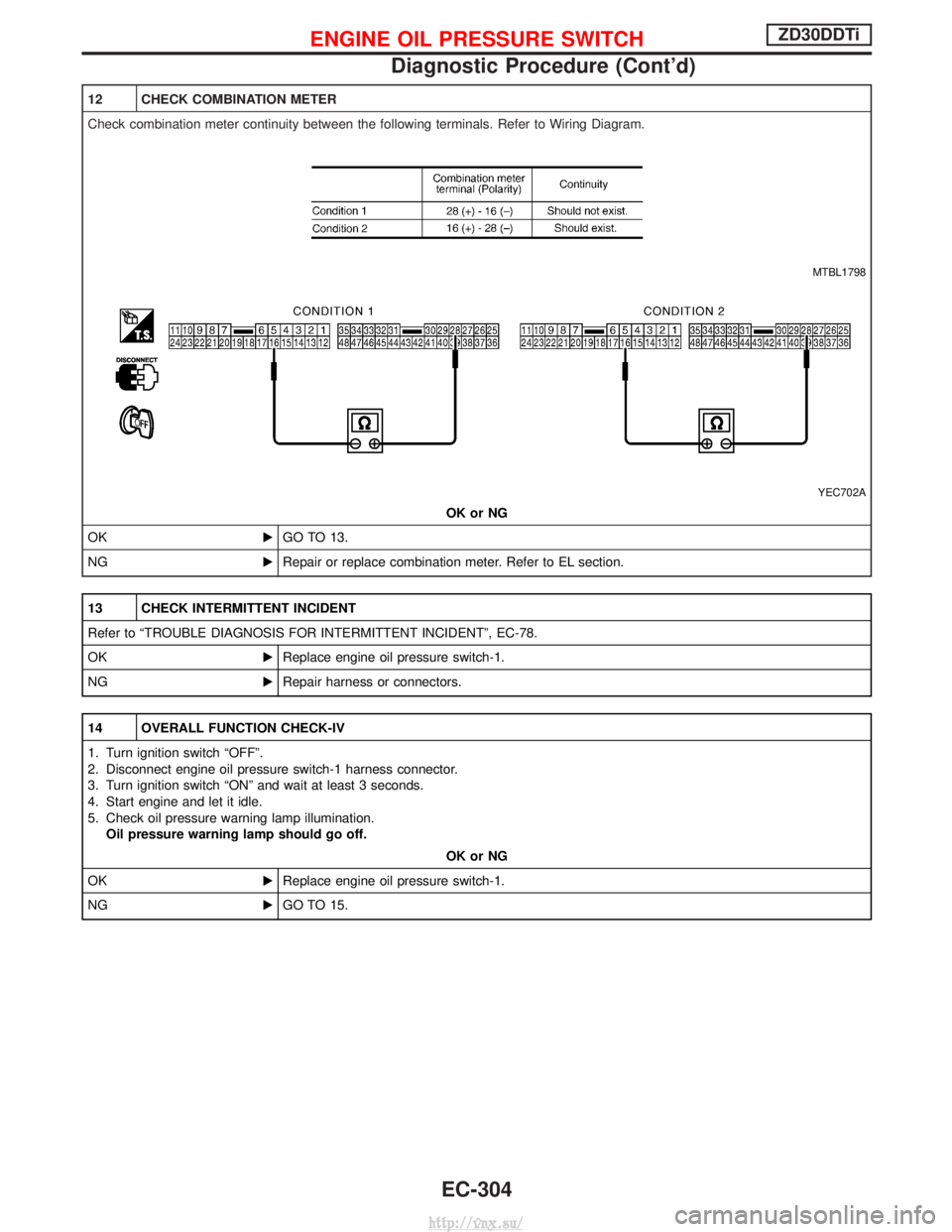
12 CHECK COMBINATION METER
Check combination meter continuity between the following terminals. Refer to Wiring Diagram.
MTBL1798
YEC702A
OK or NG
OK EGO TO 13.
NG ERepair or replace combination meter. Refer to EL section.
13 CHECK INTERMITTENT INCIDENT
Refer to ªTROUBLE DIAGNOSIS FOR INTERMITTENT INCIDENTº, EC-78.
OK EReplace engine oil pressure switch-1.
NG ERepair harness or connectors.
14 OVERALL FUNCTION CHECK-IV
1. Turn ignition switch ªOFFº.
2. Disconnect engine oil pressure switch-1 harness connector.
3. Turn ignition switch ªONº and wait at least 3 seconds.
4. Start engine and let it idle.
5. Check oil pressure warning lamp illumination.
Oil pressure warning lamp should go off.
OK or NG
OK EReplace engine oil pressure switch-1.
NG EGO TO 15.
ENGINE OIL PRESSURE SWITCHZD30DDTi
Diagnostic Procedure (Cont'd)
EC-304
http://vnx.su/
Page 582 of 1833
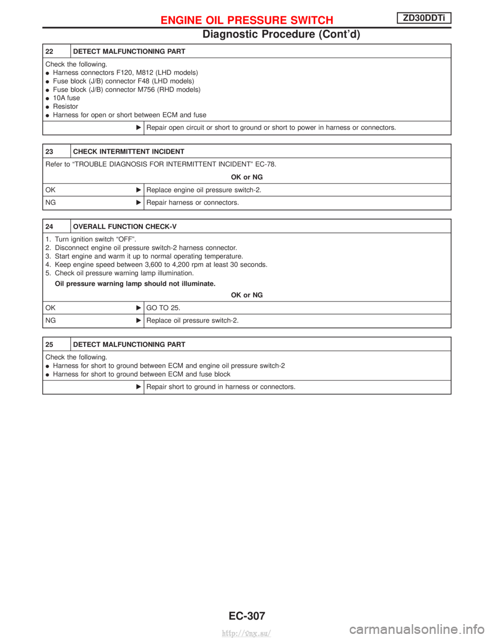
22 DETECT MALFUNCTIONING PART
Check the following.
IHarness connectors F120, M812 (LHD models)
I Fuse block (J/B) connector F48 (LHD models)
I Fuse block (J/B) connector M756 (RHD models)
I 10A fuse
I Resistor
I Harness for open or short between ECM and fuse
ERepair open circuit or short to ground or short to power in harness or connectors.
23 CHECK INTERMITTENT INCIDENT
Refer to ªTROUBLE DIAGNOSIS FOR INTERMITTENT INCIDENTº EC-78.
OK or NG
OK EReplace engine oil pressure switch-2.
NG ERepair harness or connectors.
24 OVERALL FUNCTION CHECK-V
1. Turn ignition switch ªOFFº.
2. Disconnect engine oil pressure switch-2 harness connector.
3. Start engine and warm it up to normal operating temperature.
4. Keep engine speed between 3,600 to 4,200 rpm at least 30 seconds.
5. Check oil pressure warning lamp illumination.
Oil pressure warning lamp should not illuminate.
OK or NG
OK EGO TO 25.
NG EReplace oil pressure switch-2.
25 DETECT MALFUNCTIONING PART
Check the following.
IHarness for short to ground between ECM and engine oil pressure switch-2
I Harness for short to ground between ECM and fuse block
ERepair short to ground in harness or connectors.
ENGINE OIL PRESSURE SWITCHZD30DDTi
Diagnostic Procedure (Cont'd)
EC-307
http://vnx.su/
Page 590 of 1833
Precautions
SUPPLEMENTAL RESTRAINT SYSTEM (SRS) ªAIR BAGº AND ªSEAT BELT
PRE-TENSIONERº
The Supplemental Restraint System such as ªAIR BAGº and ªSEAT BELT PRE-TENSIONERº used along with
a seat belt, helps to reduce the risk or severity of injury to the driver and front passenger for certain types of
collision. The SRS composition which is available to NISSAN MODEL R20 is as follows (The composition
varies according to the destination and optional equipment.):
IFor a frontal collision
The Supplemental Restraint System consists of driver air bag module (located in the center of the steer-
ing wheel), front passenger air bag module (located on the instrument panel on passenger side), front seat
belt pre-tensioners, a diagnosis sensor unit, warning lamp, wiring harness and spiral cable.
I For a side collision
The Supplemental Restraint System consists of front side air bag module (located in the outer side of front
seat), side air bag (satellite) sensor, diagnosis sensor unit (one of components of air bags for a frontal
collision), wiring harness, warning lamp (one of components of air bags for a frontal collision).
WARNING:
I To avoid rendering the SRS inoperative, which could increase the risk of personal injury or death
in the event of a collision which would result in air bag inflation, all maintenance should be per-
formed by an authorized NISSAN dealer.
I Improper maintenance, including incorrect removal and installation of the SRS, can lead to per-
sonal injury caused by unintentional activation of the system.
I Do not use electrical test equipment on any circuit related to the SRS unless instructed to in this
Service Manual. Spiral cable and wiring harnesses covered with yellow insulation tape either just
before the harness connectors or for the complete harness are related to the SRS.
PRECAUTIONS
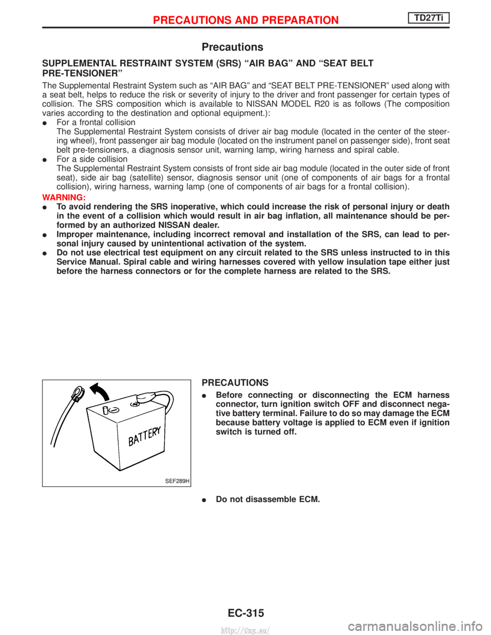
IBefore connecting or disconnecting the ECM harness
connector, turn ignition switch OFF and disconnect nega-
tive battery terminal. Failure to do so may damage the ECM
because battery voltage is applied to ECM even if ignition
switch is turned off.
I Do not disassemble ECM.
SEF289H
PRECAUTIONS AND PREPARATIONTD27Ti
EC-315
http://vnx.su/