Page 215 of 1833
WARNING:
a. Situate vehicle on a flat and solid surface.
b. Place chocks at front and back of rear wheels.
c. Do not remove engine until exhaust system has completelycooled off.
d. For safety during subsequent steps, the tension of wires should be slackened against the engine.
e. Be sure to hoist engine in a safe manner.
f. For engines not equipped with engine slingers, attach proper slingers and bolts described in PARTS CATALOG.
CAUTION:
I When lifting engine, be careful not to strike adjacent parts,
especially, brake lines and brake master cylinder.
I In hoisting the engine, always use engine slingers in a safe
manner.
ENGINE REMOVALTD27Ti
EM-124
http://vnx.su/
Page 245 of 1833
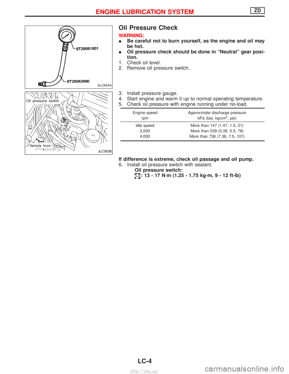
Oil Pressure Check
WARNING:
IBe careful not to burn yourself, as the engine and oil may
be hot.
I Oil pressure check should be done in ªNeutralº gear posi-
tion.
1. Check oil level.
2. Remove oil pressure switch.
3. Install pressure gauge.
4. Start engine and warm it up to normal operating temperature.
5. Check oil pressure with engine running under no-load.
Engine speed
rpm Approximate discharge pressure
kPa (bar, kg/cm2, psi)
Idle speed 2,000
4,000 More than 147 (1.47, 1.5, 21)
More than 539 (5.39, 5.5, 78)
More than 736 (7.36, 7.5, 107)
If difference is extreme, check oil passage and oil pump.
6. Install oil pressure switch with sealant. Oil pressure switch:
:13-17N ×m (1.25 - 1.75 kg-m ,9-12ft-lb)
SLC694A
JLC362B
ENGINE LUBRICATION SYSTEMZD
LC-4
http://vnx.su/
Page 251 of 1833
System Check
WARNING:
Never remove the radiator cap when the engine is hot. Serious
burns could occur from high pressure coolant escaping from
the radiator.
Wrap a thick cloth around the cap. Slowly turn it a quarter turn
to allow built-up pressure to escape. Carefully remove the cap
by turning it all the way.
CHECKING COOLING SYSTEM HOSES
Check hoses for the following:
IImproper attachment
I Leaks
I Cracks
I Damage
I Chafing
I Deterioration
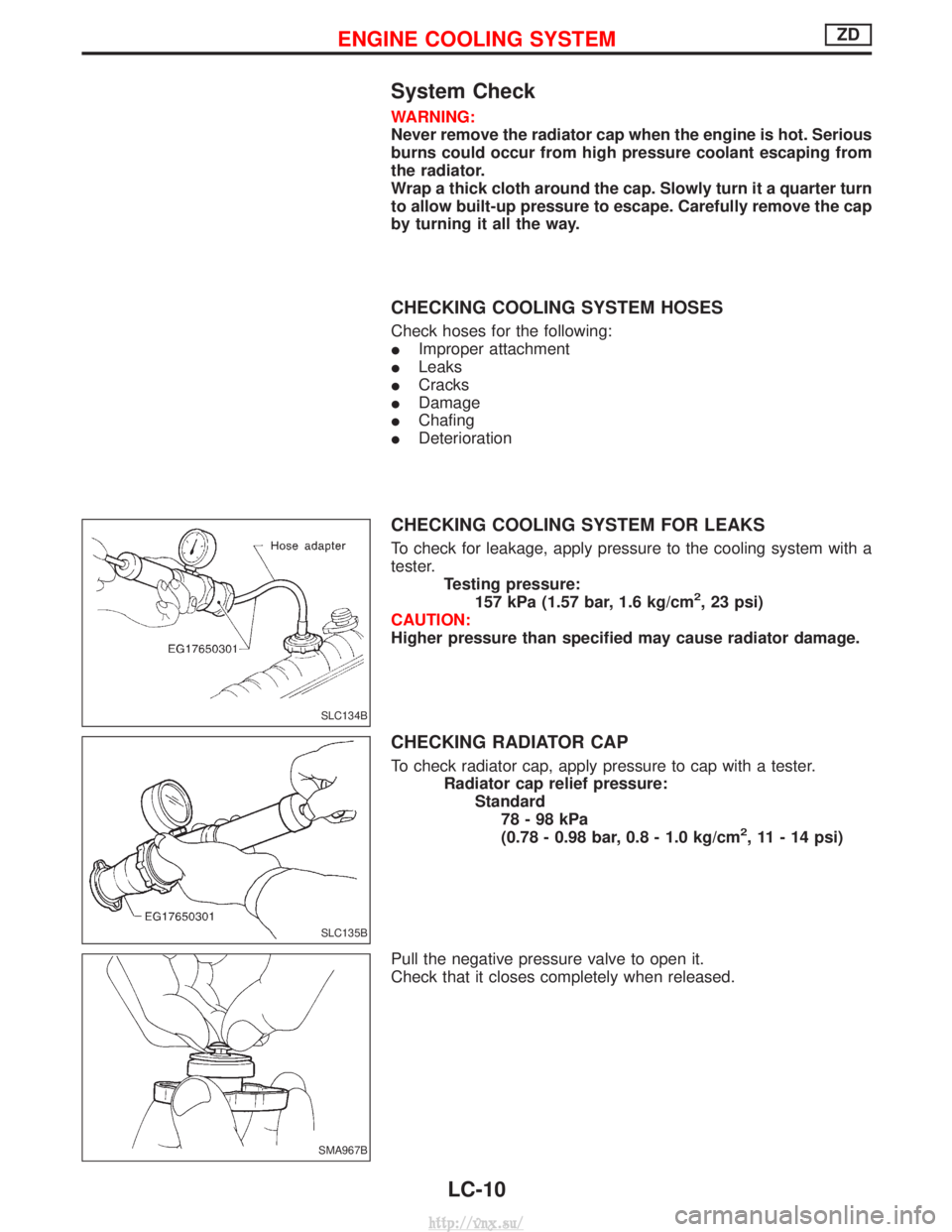
CHECKING COOLING SYSTEM FOR LEAKS
To check for leakage, apply pressure to the cooling system with a
tester.
Testing pressure:157 kPa (1.57 bar, 1.6 kg/cm
2, 23 psi)
CAUTION:
Higher pressure than specified may cause radiator damage.
CHECKING RADIATOR CAP
To check radiator cap, apply pressure to cap with a tester. Radiator cap relief pressure:Standard78-98kPa
(0.78 - 0.98 bar, 0.8 - 1.0 kg/cm
2, 11 - 14 psi)
Pull the negative pressure valve to open it.
Check that it closes completely when released.
SLC134B
SLC135B
SMA967B
ENGINE COOLING SYSTEMZD
LC-10
http://vnx.su/
Page 262 of 1833
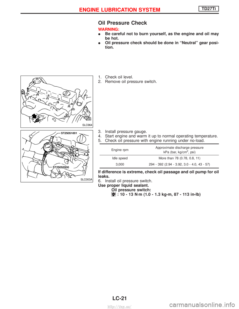
Oil Pressure Check
WARNING:
IBe careful not to burn yourself, as the engine and oil may
be hot.
I Oil pressure check should be done in ªNeutralº gear posi-
tion.
1. Check oil level.
2. Remove oil pressure switch.
3. Install pressure gauge.
4. Start engine and warm it up to normal operating temperature.
5. Check oil pressure with engine running under no-load.
Engine rpm Approximate discharge pressure
kPa (bar, kg/cm2, psi)
Idle speed More than 78 (0.78, 0.8, 11) 3,000 294 - 392 (2.94 - 3.92, 3.0 - 4.0, 43 - 57)
If difference is extreme, check oil passage and oil pump for oil
leaks.
6. Install oil pressure switch.
Use proper liquid sealant. Oil pressure switch:
:10-13N ×m (1.0 - 1.3 kg-m, 87 - 113 in-lb)
SLC964
SLC003A
ENGINE LUBRICATION SYSTEMTD27Ti
LC-21
http://vnx.su/
Page 300 of 1833
Installation
IInstall the injection tubes, referring to the markings made dur-
ing removal.
I Install the injection tubes in the order of No. 3, No. 4, No. 1, and
No. 2.
Injection nozzle oil seal
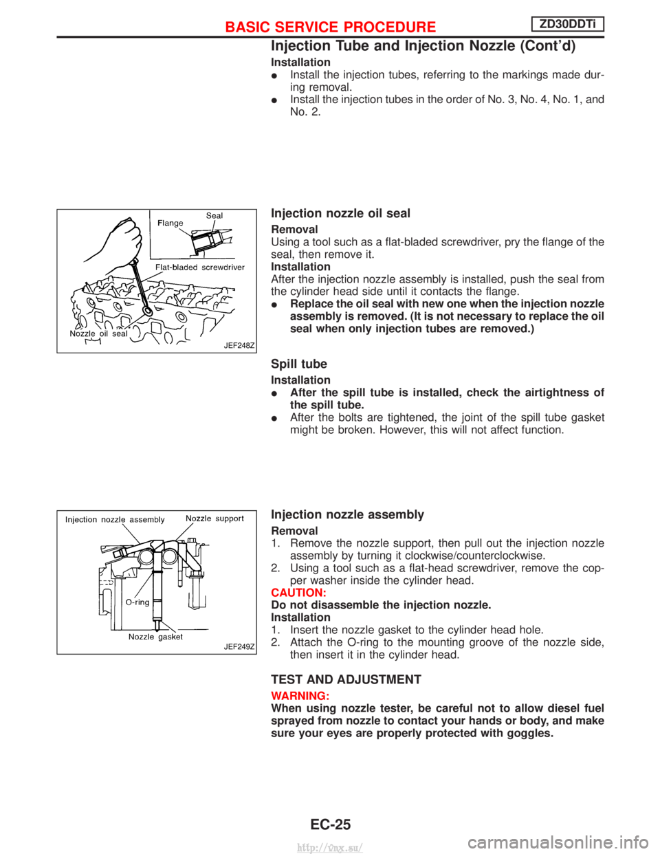
Removal
Using a tool such as a flat-bladed screwdriver, pry the flange of the
seal, then remove it.
Installation
After the injection nozzle assembly is installed, push the seal from
the cylinder head side until it contacts the flange.
IReplace the oil seal with new one when the injection nozzle
assembly is removed. (It is not necessary to replace the oil
seal when only injection tubes are removed.)
Spill tube
Installation
IAfter the spill tube is installed, check the airtightness of
the spill tube.
I After the bolts are tightened, the joint of the spill tube gasket
might be broken. However, this will not affect function.
Injection nozzle assembly
Removal
1. Remove the nozzle support, then pull out the injection nozzle
assembly by turning it clockwise/counterclockwise.
2. Using a tool such as a flat-head screwdriver, remove the cop- per washer inside the cylinder head.
CAUTION:
Do not disassemble the injection nozzle.
Installation
1. Insert the nozzle gasket to the cylinder head hole.
2. Attach the O-ring to the mounting groove of the nozzle side, then insert it in the cylinder head.
TEST AND ADJUSTMENT
WARNING:
When using nozzle tester, be careful not to allow diesel fuel
sprayed from nozzle to contact your hands or body, and make
sure your eyes are properly protected with goggles.
JEF248Z
JEF249Z
BASIC SERVICE PROCEDUREZD30DDTi
Injection Tube and Injection Nozzle (Cont'd)
EC-25
http://vnx.su/
Page 309 of 1833
IIf the battery is disconnected, the emission-related diagnostic information will be lost after approx.
24 hours.
I Erasing the emission-related diagnostic information using CONSULT-II is easier and quicker than
switching the diagnostic test mode using the data link connector.
NATS (Nissan Anti-Theft System)
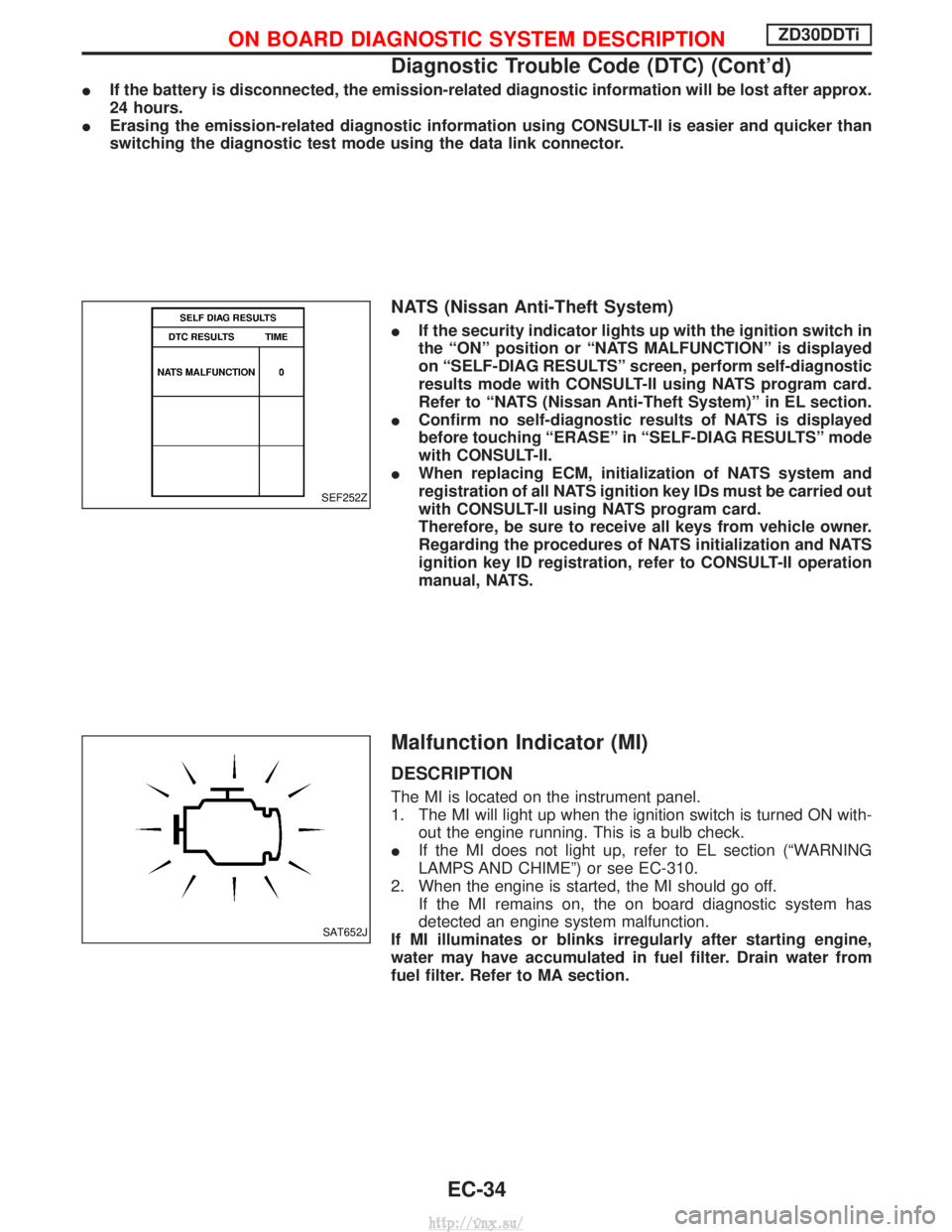
IIf the security indicator lights up with the ignition switch in
the ªONº position or ªNATS MALFUNCTIONº is displayed
on ªSELF-DIAG RESULTSº screen, perform self-diagnostic
results mode with CONSULT-II using NATS program card.
Refer to ªNATS (Nissan Anti-Theft System)º in EL section.
I Confirm no self-diagnostic results of NATS is displayed
before touching ªERASEº in ªSELF-DIAG RESULTSº mode
with CONSULT-II.
I When replacing ECM, initialization of NATS system and
registration of all NATS ignition key IDs must be carried out
with CONSULT-II using NATS program card.
Therefore, be sure to receive all keys from vehicle owner.
Regarding the procedures of NATS initialization and NATS
ignition key ID registration, refer to CONSULT-II operation
manual, NATS.
Malfunction Indicator (MI)
DESCRIPTION
The MI is located on the instrument panel.
1. The MI will light up when the ignition switch is turned ON with-
out the engine running. This is a bulb check.
I If the MI does not light up, refer to EL section (ªWARNING
LAMPS AND CHIMEº) or see EC-310.
2. When the engine is started, the MI should go off. If the MI remains on, the on board diagnostic system has
detected an engine system malfunction.
If MI illuminates or blinks irregularly after starting engine,
water may have accumulated in fuel filter. Drain water from
fuel filter. Refer to MA section.
SEF252Z
SAT652J
ON BOARD DIAGNOSTIC SYSTEM DESCRIPTIONZD30DDTi
Diagnostic Trouble Code (DTC) (Cont'd)
EC-34
http://vnx.su/
Page 310 of 1833
On board diagnostic system function
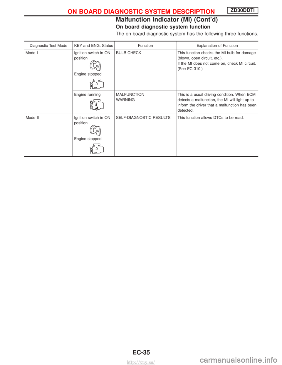
The on board diagnostic system has the following three functions.
Diagnostic Test Mode KEY and ENG. StatusFunctionExplanation of Function
Mode I Ignition switch in ON
position
Engine stopped
BULB CHECK This function checks the MI bulb for damage
(blown, open circuit, etc.).
If the MI does not come on, check MI circuit.
(See EC-310.)
Engine running
MALFUNCTION
WARNING This is a usual driving condition. When ECM
detects a malfunction, the MI will light up to
inform the driver that a malfunction has been
detected.
Mode II Ignition switch in ON position
Engine stopped
SELF-DIAGNOSTIC RESULTS This function allows DTCs to be read.
ON BOARD DIAGNOSTIC SYSTEM DESCRIPTIONZD30DDTi
Malfunction Indicator (MI) (Cont'd)
EC-35
http://vnx.su/
Page 312 of 1833
Diagnostic test mode I Ð Bulb check
In this mode, the MI on the instrument panel should stay ON. If it remains OFF, check the bulb. Refer to EL
section, ªWARNING LAMPS AND CHIMEº or see EC-310.
Diagnostic test mode I Ð Malfunction warning
MICondition
ON When the malfunction is detected or the ECM's CPU is malfunctioning.
OFF No malfunction.
Diagnostic test mode II Ð Self-diagnostic results
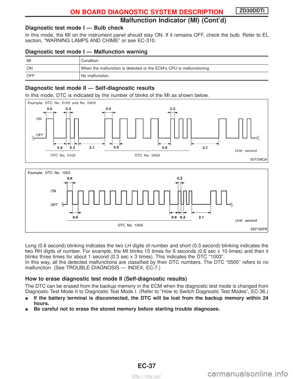
In this mode, DTC is indicated by the number of blinks of the MI as shown below.
Long (0.6 second) blinking indicates the two LH digits of number and short (0.3 second) blinking indicates the
two RH digits of number. For example, the MI blinks 10 times for 6 seconds (0.6 sec x 10 times) and then it
blinks three times for about 1 second (0.3 sec x 3 times). This indicates the DTC ª1003º.
In this way, all the detected malfunctions are classified by their DTC numbers. The DTC ª0505º refers to no
malfunction. (See TROUBLE DIAGNOSIS Ð INDEX, EC-7.)
How to erase diagnostic test mode II (Self-diagnostic results)
The DTC can be erased from the backup memory in the ECM when the diagnostic test mode is changed from
Diagnostic Test Mode II to Diagnostic Test Mode I. (Refer to ªHow to Switch Diagnostic Test Modesº, EC-36.)
I If the battery terminal is disconnected, the DTC will be lost from the backup memory within 24
hours.
I Be careful not to erase the stored memory before starting trouble diagnoses.
SEF298QA
SEF162PB
ON BOARD DIAGNOSTIC SYSTEM DESCRIPTIONZD30DDTi
Malfunction Indicator (MI) (Cont'd)
EC-37
http://vnx.su/