Page 1200 of 1833
Removal
WARNING:
Clean brake lining with a vacuum dust collector.
CAUTION:
Make sure parking brake lever is released completely.
1. Release parking brake lever fully, then remove drum.
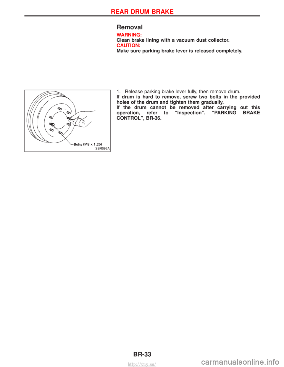
If drum is hard to remove, screw two bolts in the provided
holes of the drum and tighten them gradually.
If the drum cannot be removed after carrying out this
operation, refer to ªInspectionº, ªPARKING BRAKE
CONTROLº, BR-36.
SBR093A
REAR DRUM BRAKE
BR-33
http://vnx.su/
Page 1203 of 1833
Removal and Installation
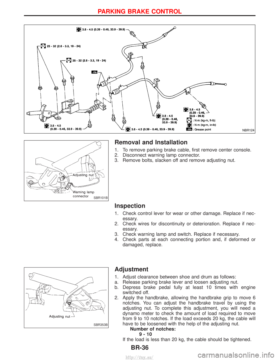
1. To remove parking brake cable, first remove center console.
2. Disconnect warning lamp connector.
3. Remove bolts, slacken off and remove adjusting nut.
Inspection
1. Check control lever for wear or other damage. Replace if nec-essary.
2. Check wires for discontinuity or deterioration. Replace if nec- essary.
3. Check warning lamp and switch. Replace if necessary.
4. Check parts at each connecting portion and, if deformed or damaged, replace.
Adjustment
1. Adjust clearance between shoe and drum as follows:
a. Release parking brake lever and loosen adjusting nut.
b. Depress brake pedal fully at least 10 times with engineswitched off.
2. Apply the handbrake, allowing the handbrake grip to move 6 notches. You can adjust the handbrake travel by using the
adjusting nut. To complete this adjustment, you will need a
dynamo meter to check the amount of load required to move
from 9 to 10 notches. If the load exceeds 20 kg, the cable will
have to be loosened with the help of the adjusting nut.Number of notches: 9-10
If the load is less than 20 kg, the cable should be tightened.
NBR124
SBR101B
SBR353B
PARKING BRAKE CONTROL
BR-36
http://vnx.su/
Page 1204 of 1833
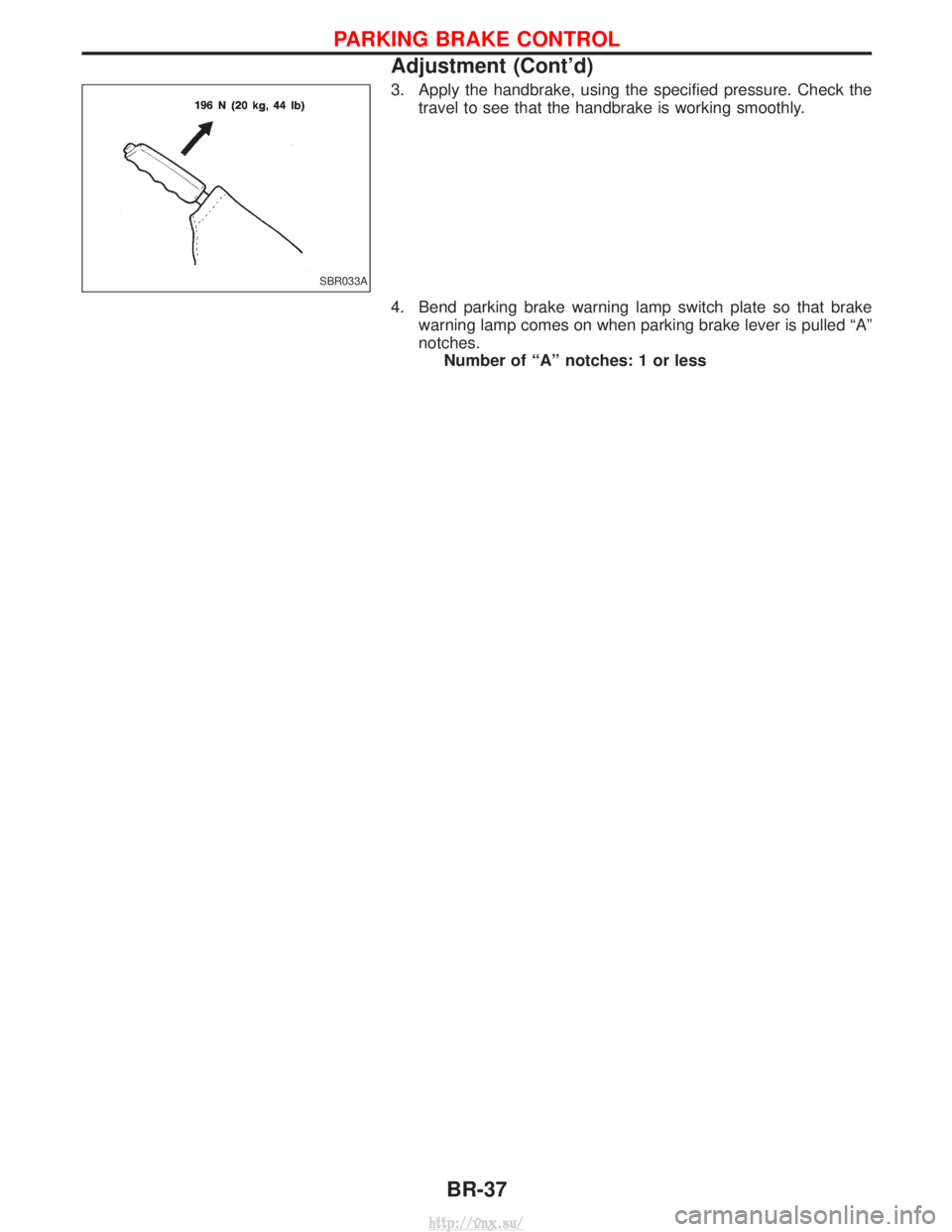
3. Apply the handbrake, using the specified pressure. Check thetravel to see that the handbrake is working smoothly.
4. Bend parking brake warning lamp switch plate so that brake warning lamp comes on when parking brake lever is pulled ªAº
notches.Number of ªAº notches: 1 or less
SBR033A
PARKING BRAKE CONTROL
Adjustment (Cont'd)
BR-37
http://vnx.su/
Page 1205 of 1833
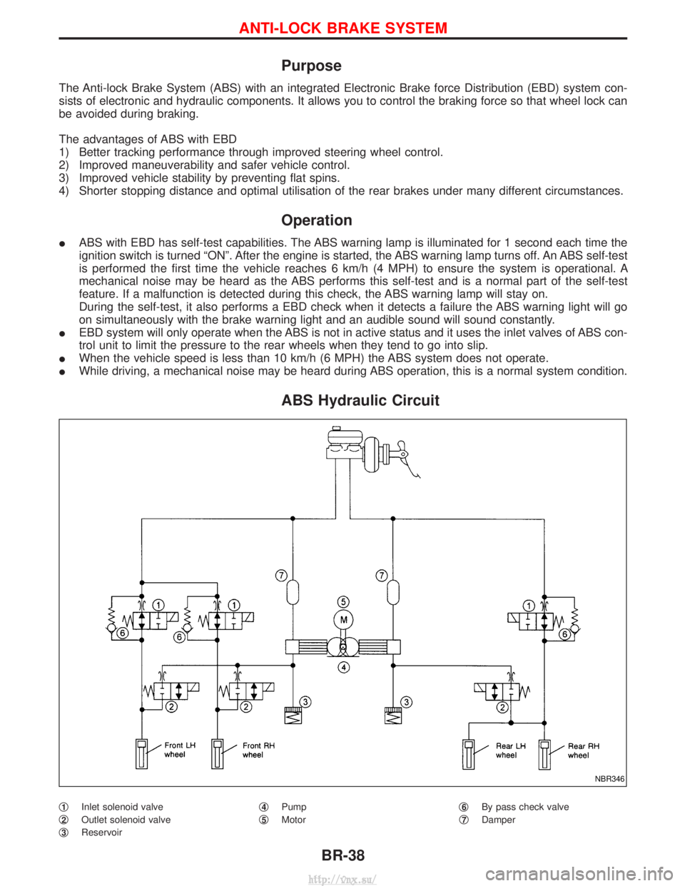
Purpose
The Anti-lock Brake System (ABS) with an integrated Electronic Brake force Distribution (EBD) system con-
sists of electronic and hydraulic components. It allows you to control the braking force so that wheel lock can
be avoided during braking.
The advantages of ABS with EBD
1) Better tracking performance through improved steering wheel control.
2) Improved maneuverability and safer vehicle control.
3) Improved vehicle stability by preventing flat spins.
4) Shorter stopping distance and optimal utilisation of the rear brakes under many different circumstances.
Operation
IABS with EBD has self-test capabilities. The ABS warning lamp is illuminated for 1 second each time the
ignition switch is turned ªONº. After the engine is started, the ABS warning lamp turns off. An ABS self-test
is performed the first time the vehicle reaches 6 km/h (4 MPH) to ensure the system is operational. A
mechanical noise may be heard as the ABS performs this self-test and is a normal part of the self-test
feature. If a malfunction is detected during this check, the ABS warning lamp will stay on.
During the self-test, it also performs a EBD check when it detects a failure the ABS warning light will go
on simultaneously with the brake warning light and an audible sound will sound constantly.
I EBD system will only operate when the ABS is not in active status and it uses the inlet valves of ABS con-
trol unit to limit the pressure to the rear wheels when they tend to go into slip.
I When the vehicle speed is less than 10 km/h (6 MPH) the ABS system does not operate.
I While driving, a mechanical noise may be heard during ABS operation, this is a normal system condition.
ABS Hydraulic Circuit
q1Inlet solenoid valve
q
2Outlet solenoid valve
q
3Reservoir q
4Pump
q
5Motor q
6By pass check valve
q
7Damper
NBR346
ANTI-LOCK BRAKE SYSTEM
BR-38
http://vnx.su/
Page 1206 of 1833
System Description
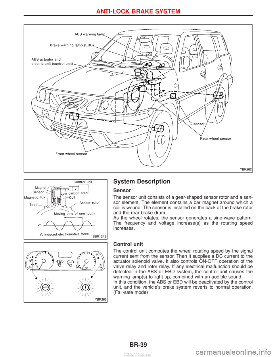
Sensor
The sensor unit consists of a gear-shaped sensor rotor and a sen-
sor element. The element contains a bar magnet around which a
coil is wound. The sensor is installed on the back of the brake rotor
and the rear brake drum.
As the wheel rotates, the sensor generates a sine-wave pattern.
The frequency and voltage increase(s) as the rotating speed
increases.
Control unit
The control unit computes the wheel rotating speed by the signal
current sent from the sensor. Then it supplies a DC current to the
actuator solenoid valve. It also controls ON-OFF operation of the
valve relay and rotor relay. If any electrical malfunction should be
detected in the ABS or EBD system, the control unit causes the
warning lamp(s) to light up, combined with an audible sound.
In this condition, the ABS or EBD will be deactivated by the control
unit, and the vehicle's brake system reverts to normal operation.
(Fail-safe mode)
YBR262
SBR124B
YBR263
ANTI-LOCK BRAKE SYSTEM
BR-39
http://vnx.su/
Page 1226 of 1833
CONSULT-II
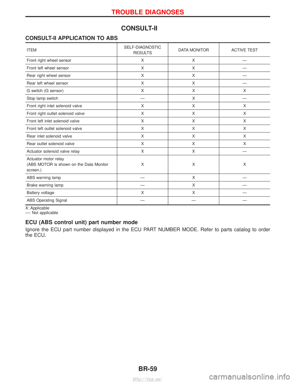
CONSULT-II APPLICATION TO ABS
ITEMSELF-DIAGNOSTIC
RESULTS DATA MONITOR ACTIVE TEST
Front right wheel sensor X X Ð
Front left wheel sensor X X Ð
Rear right wheel sensor X X Ð
Rear left wheel sensor X X Ð
G switch (G sensor) X X X
Stop lamp switch Ð X Ð
Front right inlet solenoid valve X X X
Front right outlet solenoid valve X X X
Front left inlet solenoid valve X X X
Front left outlet solenoid valve X X X
Rear inlet solenoid valve X X X
Rear outlet solenoid valve X X X
Actuator solenoid valve relay X X Ð
Actuator motor relay
(ABS MOTOR is shown on the Data Monitor
screen.) XXX
ABS warning lamp Ð X Ð
Brake warning lamp Ð X Ð
Battery voltage X X Ð
ABS Operating Signal Ð Ð Ð
X: Applicable
Ð: Not applicable
ECU (ABS control unit) part number mode
Ignore the ECU part number displayed in the ECU PART NUMBER MODE. Refer to parts catalog to order
the ECU.
TROUBLE DIAGNOSES
BR-59
http://vnx.su/
Page 1227 of 1833
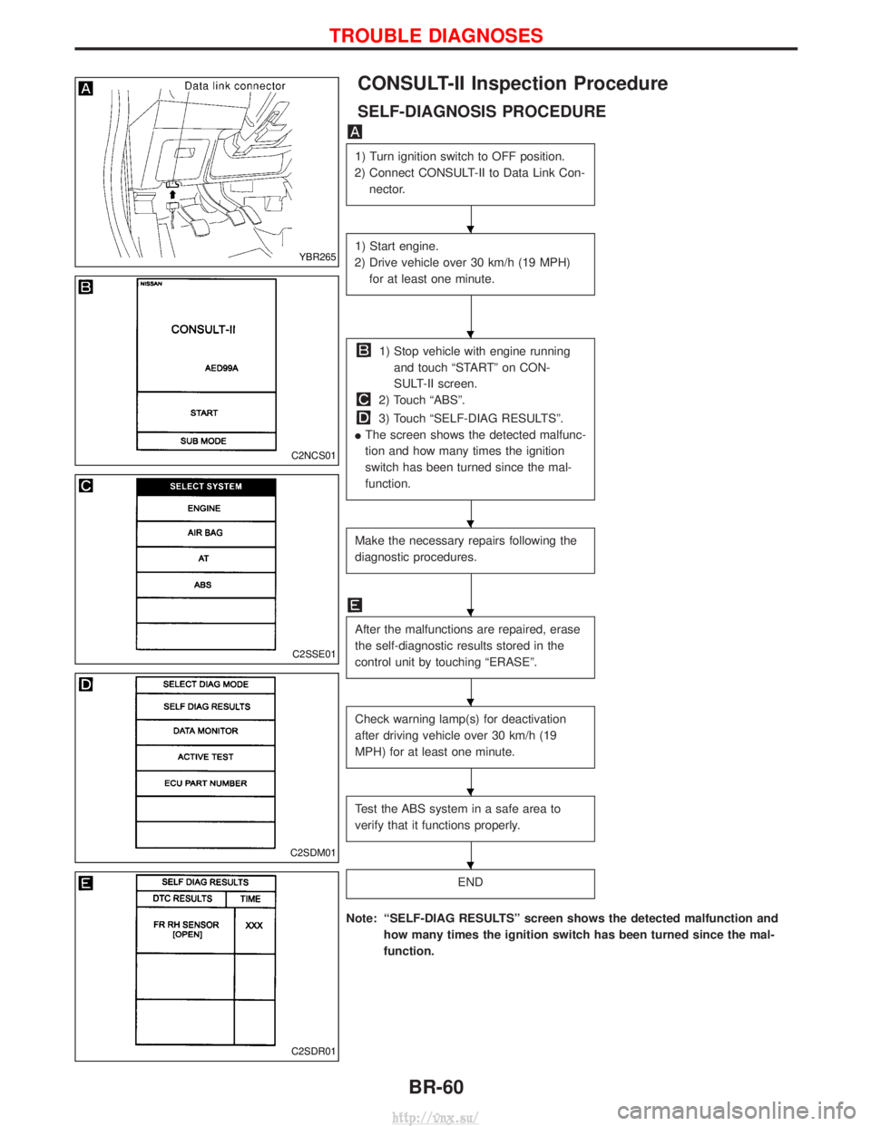
CONSULT-II Inspection Procedure
SELF-DIAGNOSIS PROCEDURE
1) Turn ignition switch to OFF position.
2) Connect CONSULT-II to Data Link Con- nector.
1) Start engine.
2) Drive vehicle over 30 km/h (19 MPH) for at least one minute.
1) Stop vehicle with engine runningand touch ªSTARTº on CON-
SULT-II screen.
2) Touch ªABSº.
3) Touch ªSELF-DIAG RESULTSº.
I The screen shows the detected malfunc-
tion and how many times the ignition
switch has been turned since the mal-
function.
Make the necessary repairs following the
diagnostic procedures.
After the malfunctions are repaired, erase
the self-diagnostic results stored in the
control unit by touching ªERASEº.
Check warning lamp(s) for deactivation
after driving vehicle over 30 km/h (19
MPH) for at least one minute.
Test the ABS system in a safe area to
verify that it functions properly.
END
Note: ªSELF-DIAG RESULTSº screen shows the detected malfunction and
how many times the ignition switch has been turned since the mal-
function.
YBR265
C2NCS01
C2SSE01
C2SDM01
C2SDR01
H
H
H
H
H
H
H
TROUBLE DIAGNOSES
BR-60
http://vnx.su/
Page 1228 of 1833
![NISSAN TERRANO 2004 Service Repair Manual SELF-DIAGNOSTIC RESULTS MODE
Diagnostic itemDiagnostic item is detected when... Diagnostic
procedure
FR RH SENSORH
[OPEN] I
Circuit for front right wheel sensor is open.
(An abnormally high input volt](/manual-img/5/57394/w960_57394-1227.png "NISSAN TERRANO 2004 Service Repair Manual SELF-DIAGNOSTIC RESULTS MODE
Diagnostic itemDiagnostic item is detected when... Diagnostic
procedure
FR RH SENSORH
[OPEN] I
Circuit for front right wheel sensor is open.
(An abnormally high input volt")
SELF-DIAGNOSTIC RESULTS MODE
Diagnostic itemDiagnostic item is detected when... Diagnostic
procedure
FR RH SENSORH
[OPEN] I
Circuit for front right wheel sensor is open.
(An abnormally high input voltage is entered.) 4
FR LH SENSORH
[OPEN] I
Circuit for front left wheel sensor is open.
(An abnormally high input voltage is entered.) 4
RR RH SENSORH
[OPEN] I
Circuit for rear right sensor is open.
(An abnormally high input voltage is entered.) 4
RR LH SENSORH
[OPEN] I
Circuit for rear left sensor is open.
(An abnormally high input voltage is entered.) 4
FR RH SENSORH
[SHORT] I
Circuit for front right wheel sensor is shorted.
(An abnormally low input voltage is entered.) 4
FR LH SENSORH
[SHORT] I
Circuit for front left wheel sensor is shorted.
(An abnormally low input voltage is entered.) 4
RR RH SENSORH
[SHORT] I
Circuit for rear right sensor is shorted.
(An abnormally low input voltage is entered.) 4
RR LH SENSORH
[SHORT] I
Circuit for rear left sensor is shorted.
(An abnormally low input voltage is entered.) 4
ABS SENSORH
[ABNORMAL SIGNAL] I
Teeth damage on sensor rotor or misalignment of wheel sensor.
(Abnormal wheel sensor signal is entered.) 4
FR RH IN ABS SOL
[OPEN, SHORT] I
Circuit for front right inlet solenoid valve is open or shorted.
(An abnormally low output voltage is entered.) 3
FR LH IN ABS SOL
[OPEN, SHORT] I
Circuit for front left inlet solenoid valve is open or shorted.
(An abnormally low output voltage is entered.) 3
FR RH OUT ABS SOL
[OPEN, SHORT] I
Circuit for front right outlet solenoid valve is open or shorted.
(An abnormally low output voltage is entered.) 3
FR LH OUT ABS SOL
[OPEN, SHORT] I
Circuit for front left outlet solenoid valve is open or shorted.
(An abnormally low output voltage is entered.) 3
RR IN ABS SOL
[OPEN, SHORT] I
Circuit for rear right outlet solenoid valve is open or shorted.
(An abnormally high output voltage is entered.) 3
RR OUT ABS SOL
[OPEN, SHORT] I
Circuit for rear left outlet solenoid valve is open or shorted.
(An abnormally high output voltage is entered.) 3
ABS ACTUATOR RELAY
[ABNORMAL] I
Actuator solenoid valve relay is ON, even if control unit sends OFF signal.
I Actuator solenoid valve relay is OFF, even if control unit sends ON signal. 6
ABS MOTOR RELAY
[ABNORMAL] I
Circuit for ABS motor relay is open or shorted.
I Circuit for actuator motor is open or shorted.
I Actuator motor relay is stuck. 5
BATTERY VOLT
[VB-LOW] I
Power source voltage supplied to ABS control unit is abnormally low. 7
CONTROL UNIT IFunction of calculation in ABS control unit has failed. 9
G-SENSOR
[ABNORMAL] I
G sensor is open. 8
H If a tire slips on rough roads for more than 10 seconds, the ABS warning lamp may come on. In this case, the malfunctioning code
regarding the wheel sensors may be memorized. Turn off the ignition switch, restart the engine and drive the vehicle at speeds
above 30 km/h (19 MPH).
TROUBLE DIAGNOSES
CONSULT-II Inspection Procedure (Cont'd)
BR-61
http://vnx.su/