Page 1230 of 1833
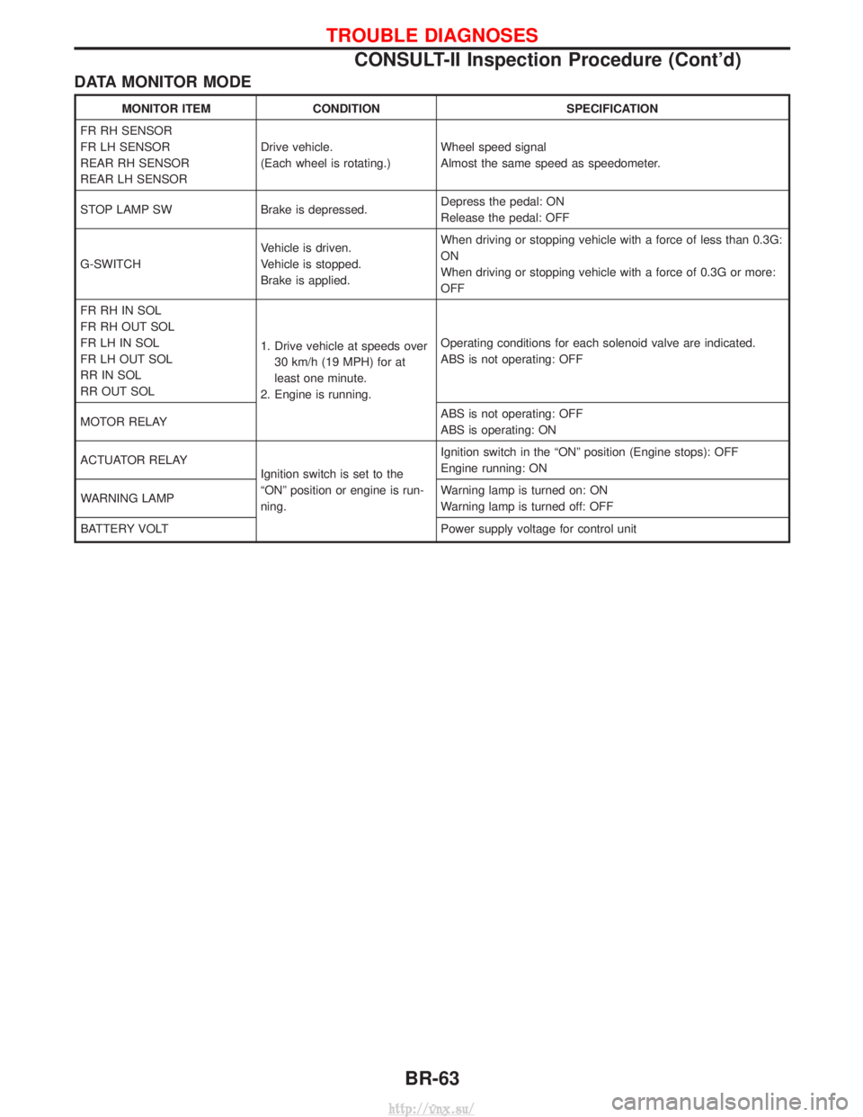
DATA MONITOR MODE
MONITOR ITEMCONDITION SPECIFICATION
FR RH SENSOR
FR LH SENSOR
REAR RH SENSOR
REAR LH SENSOR Drive vehicle.
(Each wheel is rotating.)
Wheel speed signal
Almost the same speed as speedometer.
STOP LAMP SW Brake is depressed. Depress the pedal: ON
Release the pedal: OFF
G-SWITCH Vehicle is driven.
Vehicle is stopped.
Brake is applied.When driving or stopping vehicle with a force of less than 0.3G:
ON
When driving or stopping vehicle with a force of 0.3G or more:
OFF
FR RH IN SOL
FR RH OUT SOL
FR LH IN SOL
FR LH OUT SOL
RR IN SOL
RR OUT SOL 1. Drive vehicle at speeds over
30 km/h (19 MPH) for at
least one minute.
2. Engine is running. Operating conditions for each solenoid valve are indicated.
ABS is not operating: OFF
MOTOR RELAY ABS is not operating: OFF
ABS is operating: ON
ACTUATOR RELAY Ignition switch is set to the
ªONº position or engine is run-
ning.Ignition switch in the ªONº position (Engine stops): OFF
Engine running: ON
WARNING LAMP Warning lamp is turned on: ON
Warning lamp is turned off: OFF
BATTERY VOLT Power supply voltage for control unit
TROUBLE DIAGNOSES
CONSULT-II Inspection Procedure (Cont'd)
BR-63
http://vnx.su/
Page 1231 of 1833
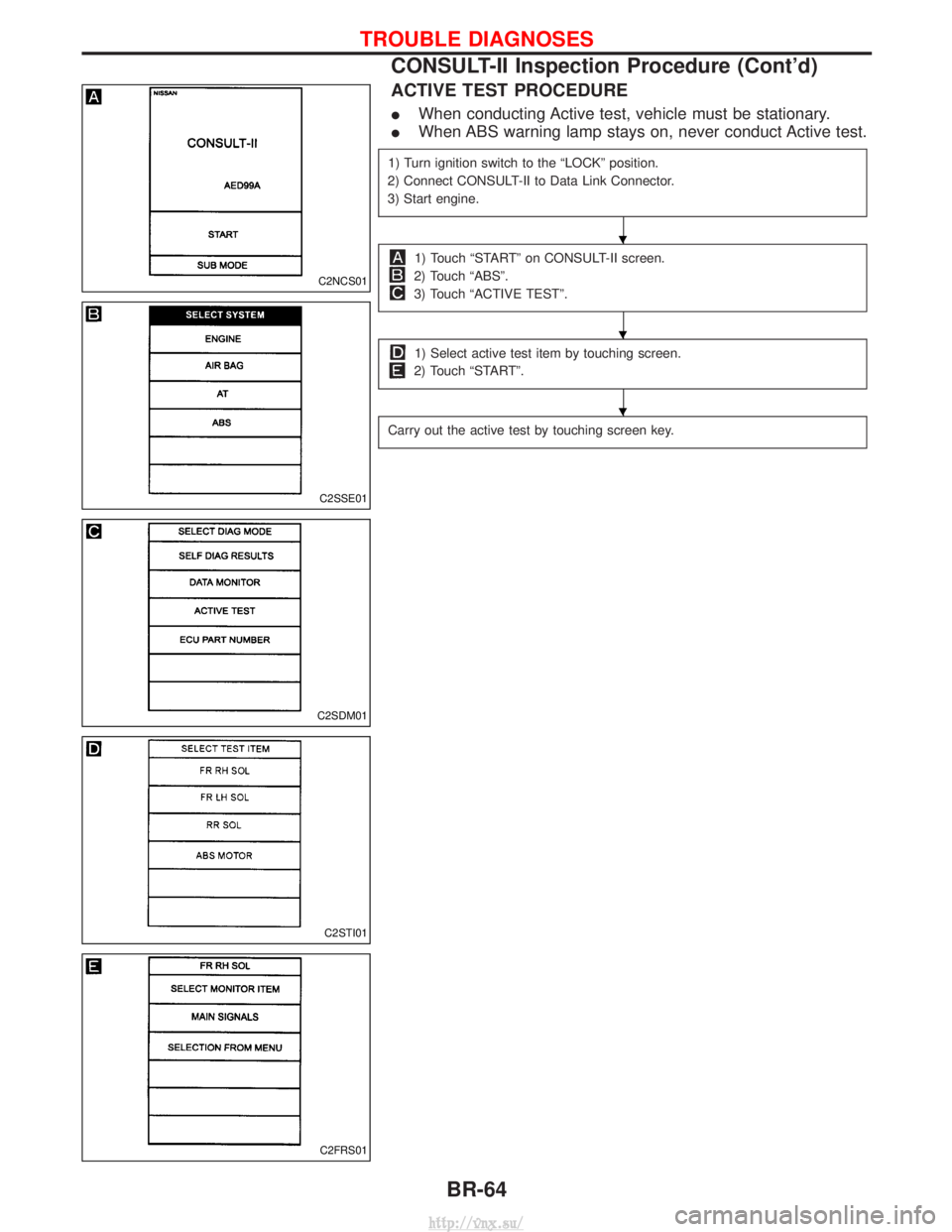
ACTIVE TEST PROCEDURE
IWhen conducting Active test, vehicle must be stationary.
I When ABS warning lamp stays on, never conduct Active test.
1) Turn ignition switch to the ªLOCKº position.
2) Connect CONSULT-II to Data Link Connector.
3) Start engine.
1) Touch ªSTARTº on CONSULT-II screen.
2) Touch ªABSº.
3) Touch ªACTIVE TESTº.
1) Select active test item by touching screen.
2) Touch ªSTARTº.
Carry out the active test by touching screen key.
C2NCS01
C2SSE01
C2SDM01
C2STI01
C2FRS01
H
H
H
TROUBLE DIAGNOSES
CONSULT-II Inspection Procedure (Cont'd)
BR-64
http://vnx.su/
Page 1233 of 1833
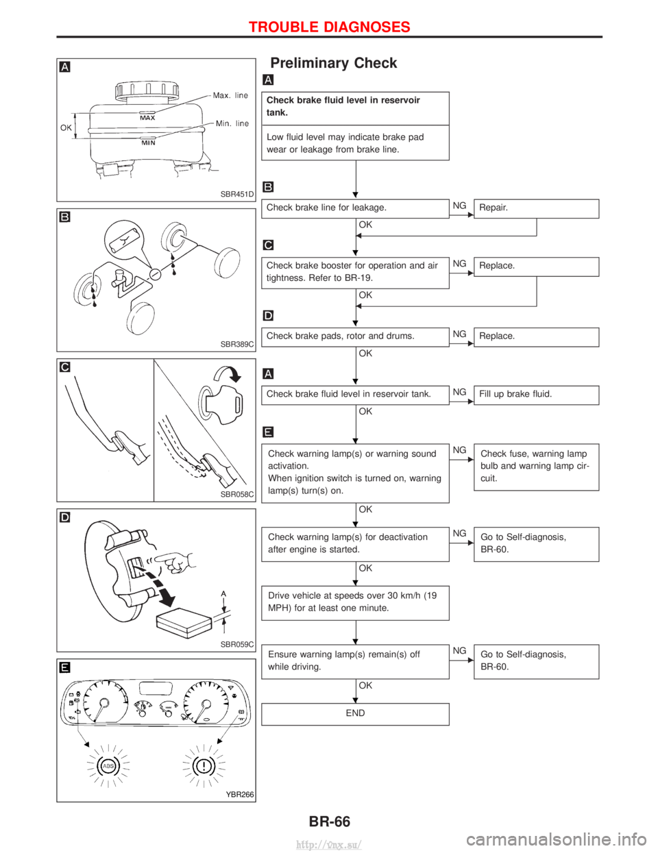
Preliminary Check
Check brake fluid level in reservoir
tank.
---------------------------------------------------------------------------------------------------------------------------------------------------------------------------------------------------------------------------------------------------------------------------------------------------------------- Low fluid level may indicate brake pad
wear or leakage from brake line.
Check brake line for leakage.
OKENG Repair.
F
Check brake booster for operation and air
tightness. Refer to BR-19.
OK
ENGReplace.
F
Check brake pads, rotor and drums.
OKENGReplace.
Check brake fluid level in reservoir tank.
OKENGFill up brake fluid.
Check warning lamp(s) or warning sound
activation.
When ignition switch is turned on, warning
lamp(s) turn(s) on.
OK
ENG
Check fuse, warning lamp
bulb and warning lamp cir-
cuit.
Check warning lamp(s) for deactivation
after engine is started.
OK
ENGGo to Self-diagnosis,
BR-60.
Drive vehicle at speeds over 30 km/h (19
MPH) for at least one minute.
Ensure warning lamp(s) remain(s) off
while driving.
OK
ENGGo to Self-diagnosis,
BR-60.
END
SBR451D
SBR389C
SBR058C
SBR059C
YBR266
H
H
H
H
H
H
H
H
H
TROUBLE DIAGNOSES
BR-66
http://vnx.su/
Page 1235 of 1833
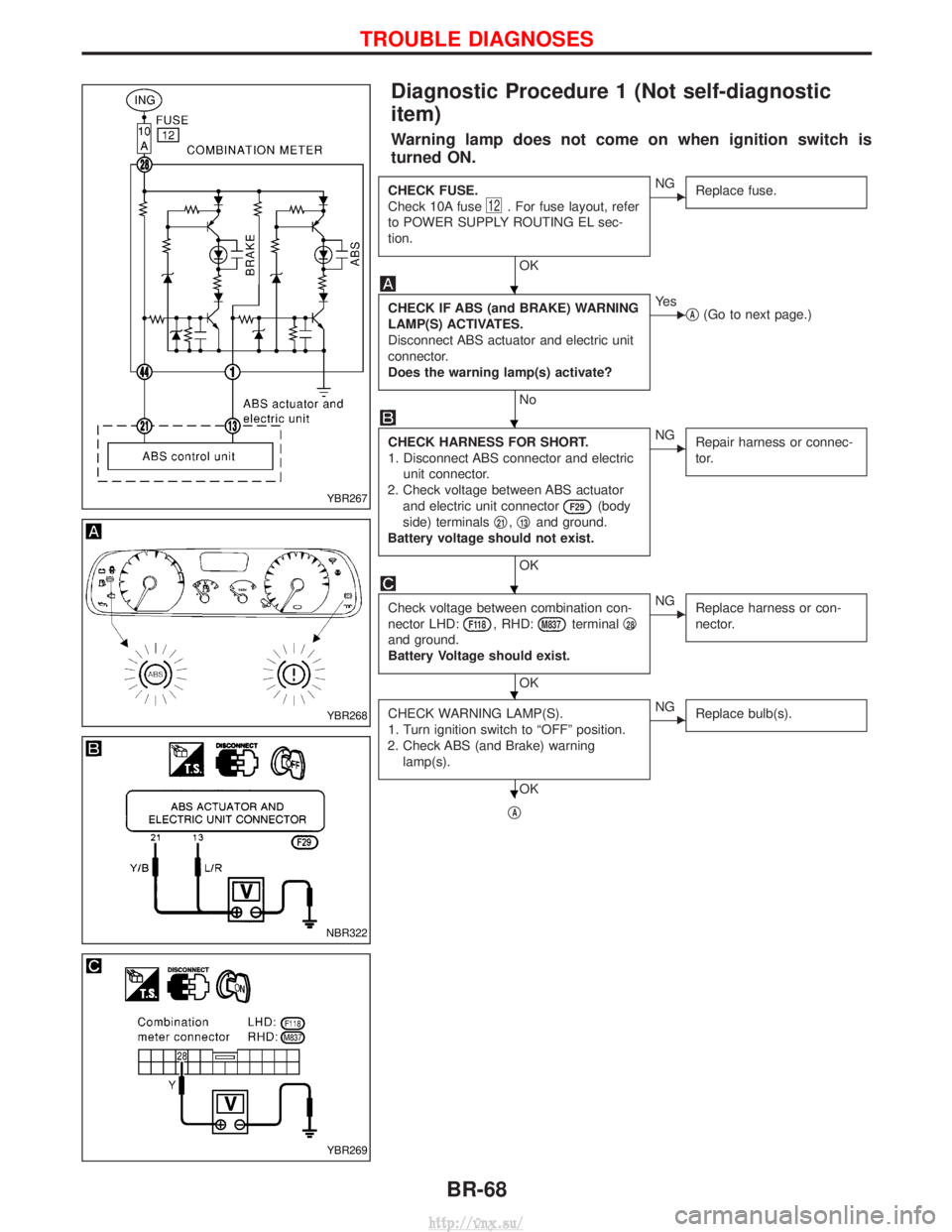
Diagnostic Procedure 1 (Not self-diagnostic
item)
Warning lamp does not come on when ignition switch is
turned ON.
CHECK FUSE.
Check 10A fuse
12. For fuse layout, refer
to POWER SUPPLY ROUTING EL sec-
tion.
OK
ENG Replace fuse.
CHECK IF ABS (and BRAKE) WARNING
LAMP(S) ACTIVATES.
Disconnect ABS actuator and electric unit
connector.
Does the warning lamp(s) activate?
No
EYe s
qA(Go to next page.)
CHECK HARNESS FOR SHORT.
1. Disconnect ABS connector and electric
unit connector.
2. Check voltage between ABS actuator and electric unit connector
F29(body
side) terminals q
21,q13and ground.
Battery voltage should not exist.
OK
ENG Repair harness or connec-
tor.
Check voltage between combination con-
nector LHD:
F118, RHD:M837terminal q28
and ground.
Battery Voltage should exist.
OK
ENG
Replace harness or con-
nector.
CHECK WARNING LAMP(S).
1. Turn ignition switch to ªOFFº position.
2. Check ABS (and Brake) warning lamp(s).
OK
ENG Replace bulb(s).
qA
YBR267
YBR268
NBR322
YBR269
H
H
H
H
H
TROUBLE DIAGNOSES
BR-68
http://vnx.su/
Page 1237 of 1833
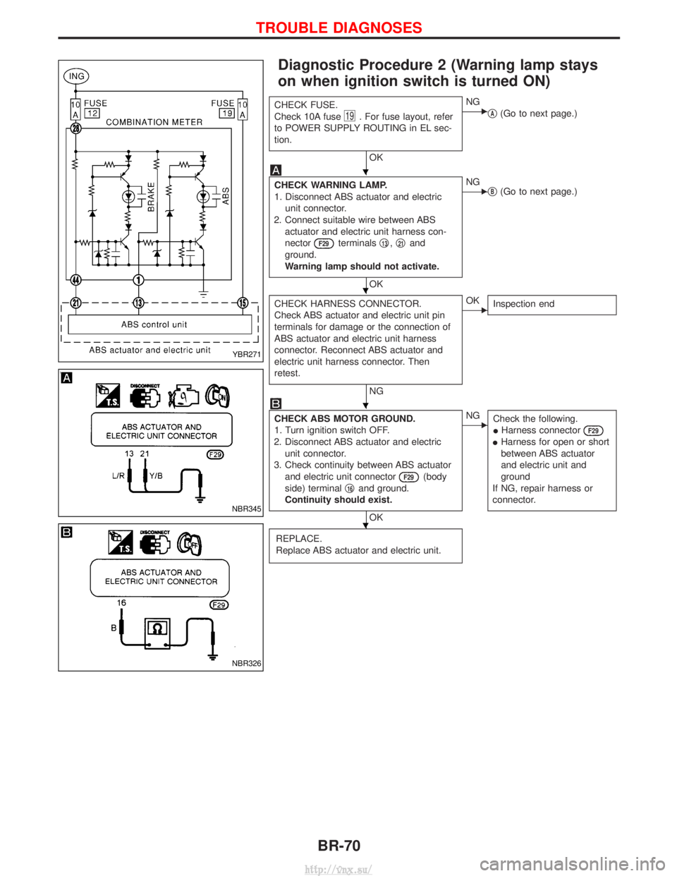
Diagnostic Procedure 2 (Warning lamp stays
on when ignition switch is turned ON)
CHECK FUSE.
Check 10A fuse
19. For fuse layout, refer
to POWER SUPPLY ROUTING in EL sec-
tion.
OK
ENG qA(Go to next page.)
CHECK WARNING LAMP.
1. Disconnect ABS actuator and electric
unit connector.
2. Connect suitable wire between ABS actuator and electric unit harness con-
nector
F29terminals q13,q21and
ground.
Warning lamp should not activate.
OK
ENG qB(Go to next page.)
CHECK HARNESS CONNECTOR.
Check ABS actuator and electric unit pin
terminals for damage or the connection of
ABS actuator and electric unit harness
connector. Reconnect ABS actuator and
electric unit harness connector. Then
retest.
NG
EOK Inspection end
CHECK ABS MOTOR GROUND.
1. Turn ignition switch OFF.
2. Disconnect ABS actuator and electric unit connector.
3. Check continuity between ABS actuator and electric unit connector
F29(body
side) terminal q
16and ground.
Continuity should exist.
OK
ENG Check the following.
IHarness connector
F29
IHarness for open or short
between ABS actuator
and electric unit and
ground
If NG, repair harness or
connector.
REPLACE.
Replace ABS actuator and electric unit.
YBR271
NBR345
NBR326
H
H
H
H
TROUBLE DIAGNOSES
BR-70
http://vnx.su/
Page 1238 of 1833
qA
REPLACE.
Replace fuse.
Does the fuse blow out when ignition
switch is turned ON?
Ye s
ENoInspection end
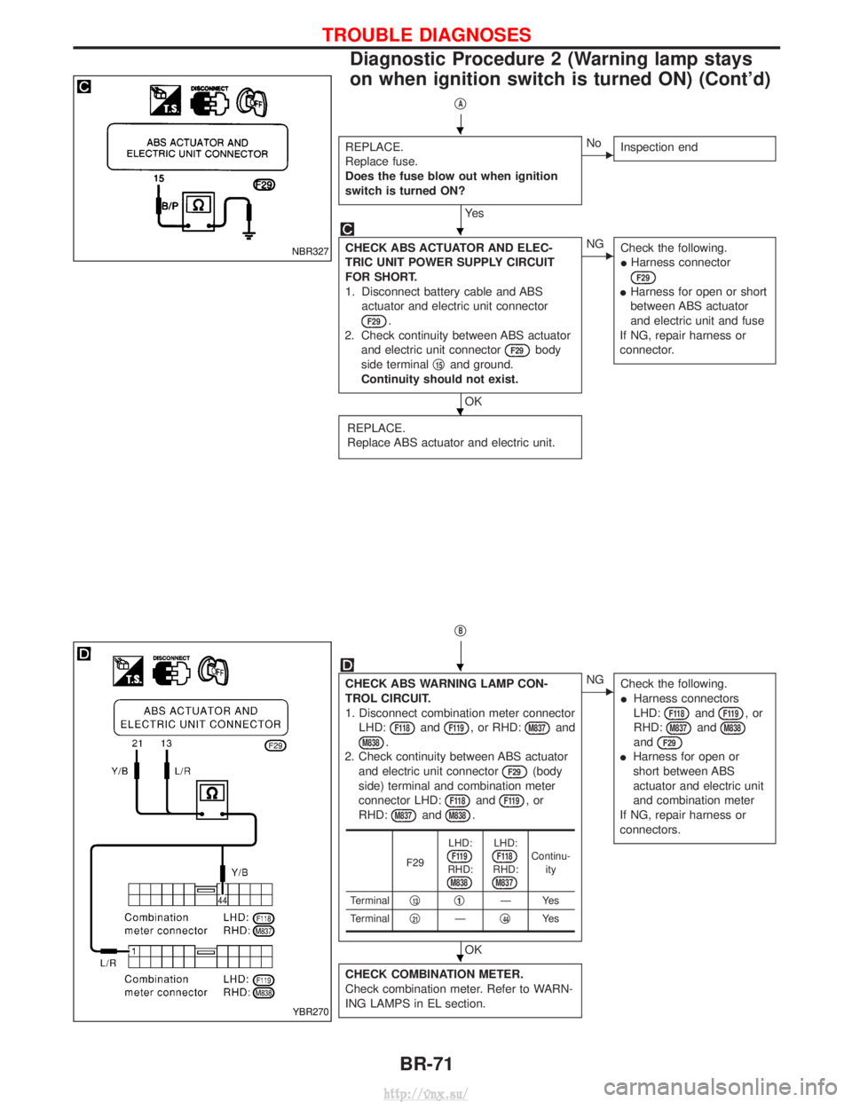
CHECK ABS ACTUATOR AND ELEC-
TRIC UNIT POWER SUPPLY CIRCUIT
FOR SHORT.
1. Disconnect battery cable and ABS
actuator and electric unit connector
F29.
2. Check continuity between ABS actuator and electric unit connector
F29body
side terminal q
15and ground.
Continuity should not exist.
OK
ENG Check the following.
IHarness connector
F29
IHarness for open or short
between ABS actuator
and electric unit and fuse
If NG, repair harness or
connector.
REPLACE.
Replace ABS actuator and electric unit.
qB
CHECK ABS WARNING LAMP CON-
TROL CIRCUIT.
1. Disconnect combination meter connector LHD:
F118andF119, or RHD:M837and
M838.
2. Check continuity between ABS actuator and electric unit connector
F29(body
side) terminal and combination meter
connector LHD:
F118andF119,or
RHD:
M837andM838.
OK
ENG Check the following.
IHarness connectors
LHD:
F118andF119,or
RHD:
M837andM838
andF29
I Harness for open or
short between ABS
actuator and electric unit
and combination meter
If NG, repair harness or
connectors.
CHECK COMBINATION METER.
Check combination meter. Refer to WARN-
ING LAMPS in EL section.
F29 LHD:F119RHD:M838
LHD:F118RHD:M837
Continu-
ity
Terminal q
13q1ÐYes
Terminal q
21Ðq44Ye s
NBR327
YBR270
H
H
H
H
H
TROUBLE DIAGNOSES
Diagnostic Procedure 2 (Warning lamp stays
on when ignition switch is turned ON) (Cont'd)
BR-71
http://vnx.su/
Page 1239 of 1833
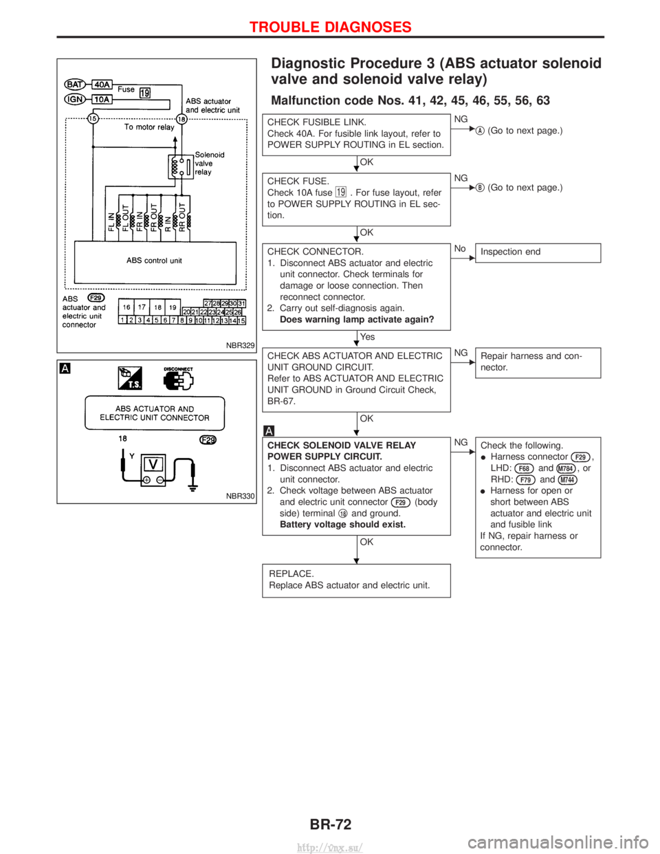
Diagnostic Procedure 3 (ABS actuator solenoid
valve and solenoid valve relay)
Malfunction code Nos. 41, 42, 45, 46, 55, 56, 63
CHECK FUSIBLE LINK.
Check 40A. For fusible link layout, refer to
POWER SUPPLY ROUTING in EL section.
OK
ENGqA(Go to next page.)
CHECK FUSE.
Check 10A fuse
19. For fuse layout, refer
to POWER SUPPLY ROUTING in EL sec-
tion.
OK
ENG qB(Go to next page.)
CHECK CONNECTOR.
1. Disconnect ABS actuator and electric unit connector. Check terminals for
damage or loose connection. Then
reconnect connector.
2. Carry out self-diagnosis again. Does warning lamp activate again?
Ye s
ENo Inspection end
CHECK ABS ACTUATOR AND ELECTRIC
UNIT GROUND CIRCUIT.
Refer to ABS ACTUATOR AND ELECTRIC
UNIT GROUND in Ground Circuit Check,
BR-67.
OK
ENGRepair harness and con-
nector.
CHECK SOLENOID VALVE RELAY
POWER SUPPLY CIRCUIT.
1. Disconnect ABS actuator and electric
unit connector.
2. Check voltage between ABS actuator and electric unit connector
F29(body
side) terminal q
18and ground.
Battery voltage should exist.
OK
ENG Check the following.
IHarness connector
F29,
LHD:
F68andM784,or
RHD:
F79andM744
I Harness for open or
short between ABS
actuator and electric unit
and fusible link
If NG, repair harness or
connector.
REPLACE.
Replace ABS actuator and electric unit.
NBR329
NBR330
H
H
H
H
H
TROUBLE DIAGNOSES
BR-72
http://vnx.su/
Page 1241 of 1833
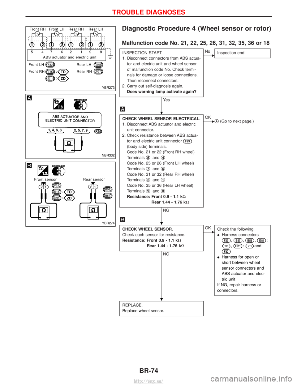
Diagnostic Procedure 4 (Wheel sensor or rotor)
Malfunction code No. 21, 22, 25, 26, 31, 32, 35, 36 or 18
INSPECTION START
1. Disconnect connectors from ABS actua-tor and electric unit and wheel sensor
of malfunction code No. Check termi-
nals for damage or loose connections.
Then reconnect connectors.
2. Carry out self-diagnosis again. Does warning lamp activate again?
Ye s
ENo Inspection end
CHECK WHEEL SENSOR ELECTRICAL.
1. Disconnect ABS actuator and electric
unit connector.
2. Check resistance between ABS actua- tor and electric unit connector
F29
(body side) terminals.
Code No. 21 or 22 (Front RH wheel)
Terminals q
5andq4
Code No. 25 or 26 (Front LH wheel)
Terminals q
7andq6
Code No. 31 or 32 (Rear RH wheel)
Terminals q
2andq1
Code No. 35 or 36 (Rear LH wheel)
Terminals q
9andq8
Resistance: Front 0.9 - 1.1 kW
Rear 1.44 - 1.76 kW
NG
EOKqA(Go to next page.)
CHECK WHEEL SENSOR.
Check each sensor for resistance.
Resistance: Front 0.9 - 1.1 kW
Rear 1.44 - 1.76 kW
NG
EOKCheck the following.
IHarness connectors
F29,B57,B58,E15:
,E211:and
F32
IHarness for open or
short between wheel
sensor connectors and
ABS actuator and elec-
tric unit
If NG, repair harness or
connectors.
REPLACE.
Replace wheel sensor.
YBR273
NBR332
YBR274
H
H
H
TROUBLE DIAGNOSES
BR-74
http://vnx.su/