2004 NISSAN TERRANO warning
[x] Cancel search: warningPage 63 of 1833
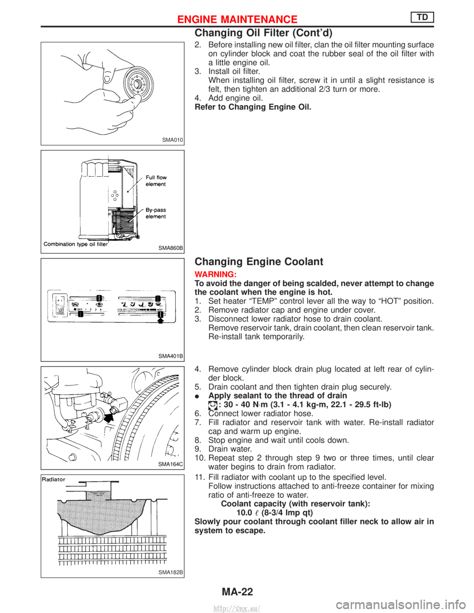
2. Before installing new oil filter, clan the oil filter mounting surfaceon cylinder block and coat the rubber seal of the oil filter with
a little engine oil.
3. Install oil filter. When installing oil filter, screw it in until a slight resistance is
felt, then tighten an additional 2/3 turn or more.
4. Add engine oil.
Refer to Changing Engine Oil.
Changing Engine Coolant
WARNING:
To avoid the danger of being scalded, never attempt to change
the coolant when the engine is hot.
1. Set heater ªTEMPº control lever all the way to ªHOTº position.
2. Remove radiator cap and engine under cover.
3. Disconnect lower radiator hose to drain coolant. Remove reservoir tank, drain coolant, then clean reservoir tank.
Re-install tank temporarily.
4. Remove cylinder block drain plug located at left rear of cylin- der block.
5. Drain coolant and then tighten drain plug securely.
I Apply sealant to the thread of drain
:30-40N ×m (3.1 - 4.1 kg-m, 22.1 - 29.5 ft-lb)
6. Connect lower radiator hose.
7. Fill radiator and reservoir tank with water. Re-install radiator cap and warm up engine.
8. Stop engine and wait until cools down.
9. Drain water.
10. Repeat step 2 through step 9 two or three times, until clear water begins to drain from radiator.
11. Fill radiator with coolant up to the specified level. Follow instructions attached to anti-freeze container for mixing
ratio of anti-freeze to water.Coolant capacity (with reservoir tank): 10.0 (8-3/4 Imp qt)
Slowly pour coolant through coolant filler neck to allow air in
system to escape.
SMA010
SMA860B
SMA401B
SMA164C
SMA182B
ENGINE MAINTENANCETD
Changing Oil Filter (Cont'd)
MA-22
http://vnx.su/
Page 66 of 1833
Pinch the rubber cap located under the cyclone air cleaner assem-
bly to remove dust.
Checking Injection Nozzle
WARNING:
When using nozzle tester, do not allow fuel sprayed from
nozzle to contact your hand or body, and make sure that your
eyes are properly protected with goggles.
1. Check initial injection pressure by pumping tester handle onetime per second.Initial injection pressure: Used Nozzle12,259 - 12,749 kPa
(122.6 - 127.5 bar, 125 - 130 kg/cm
2,
1,778 - 1,849 psi)
New Nozzle 12,749 - 13,730 kPa
(127.5 - 137.3 bar, 130 - 140 kg/cm
2,
1,849 - 1,991 psi)
I Always check initial injection pressure before installing
new nozzle.
Do not disassemble injection nozzle assembly. Entrust disas-
sembly or adjustment to BOSCH service shop.
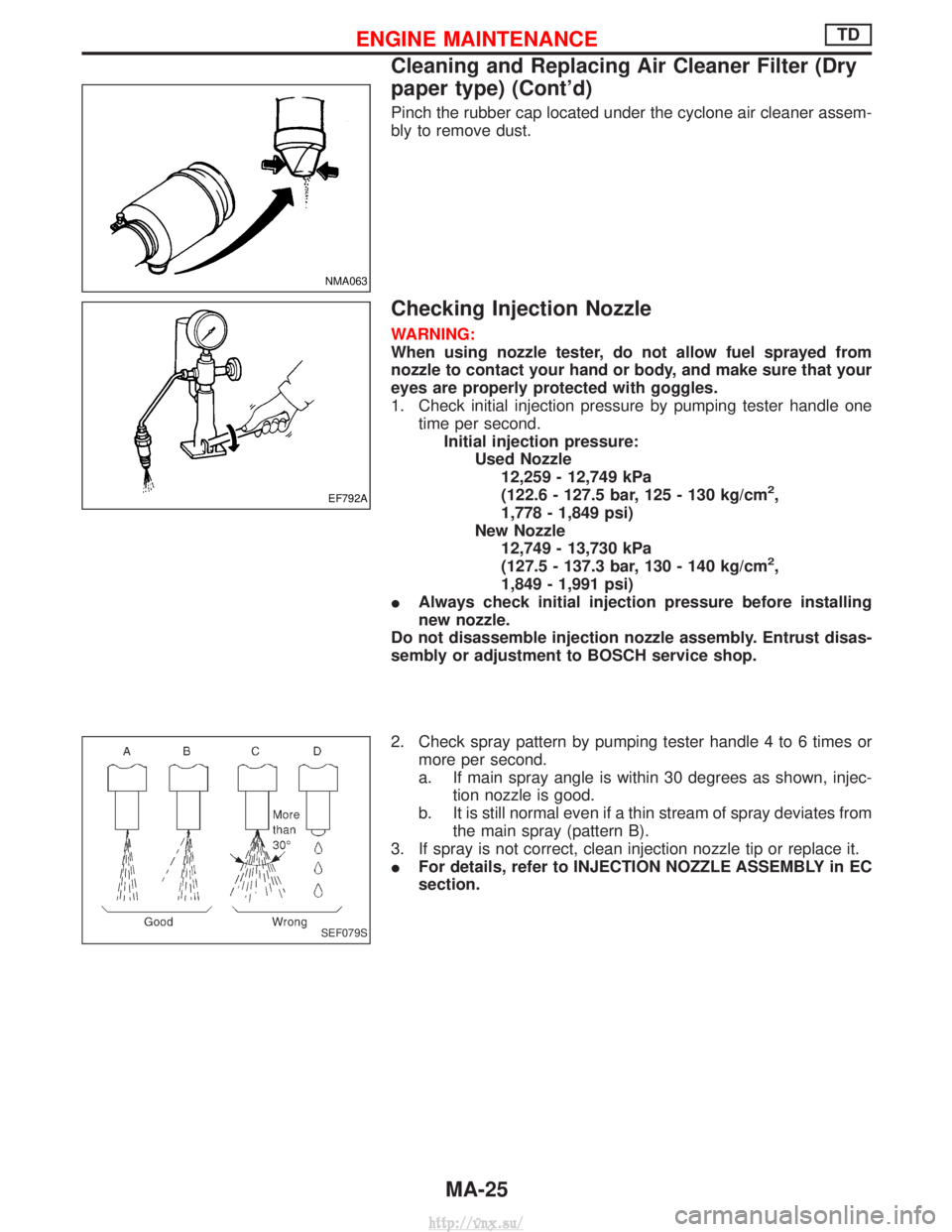
2. Check spray pattern by pumping tester handle 4 to 6 times or more per second.
a. If main spray angle is within 30 degrees as shown, injec- tion nozzle is good.
b. It is still normal even if a thin stream of spray deviates from the main spray (pattern B).
3. If spray is not correct, clean injection nozzle tip or replace it.
I For details, refer to INJECTION NOZZLE ASSEMBLY in EC
section.
NMA063
EF792A
SEF079S
ENGINE MAINTENANCETD
Cleaning and Replacing Air Cleaner Filter (Dry
paper type) (Cont'd)
MA-25
http://vnx.su/
Page 70 of 1833

Removal
WATER PUMP, ALTERNATOR AND AIR CONDITIONER
BELT
1. Remove radiator shroud.
2. Contract and hold the auto tensioner using the following proce-dure.
a. Securely hold the 19 mm (0.75 in) hexagonal portion A of auto tensioner with a closed wrench.
I Preferably use a tool with a handhold of 500 mm (19.69 in) or
more in length.
I No bolts or nuts are required to be loosened during the opera-
tion.
b. Turn the hexagonal portion A in the direction shown by the arrow to contract the damper unit of the auto tensioner.
CAUTION:
I Because the tensioner has a high tension, it shall be
securely held and turned with a closed wrench.
I Because the hexagonal portion A of the tensioner is made
of aluminum and may be damaged by sudden input, turn
it slowly according to the contraction of the damper unit.
3. Remove the belt from the alternator pulley first, and then remove it from the other pulleys.
I If the tensioner is not held firmly, your finger may get caught
between the belt and the pulleys. Confirm the holding of the
tensioner, and then hold the belt side in the place away from
the pulleys to attach or remove the belt, paying attention to
prevent your finger from being caught.
CAUTION:
I When handling the belt, pay attention to prevent the oil or
coolant from adhering to the belt.
I Do not distort or bend the belt intensively.
Installation
IInstall the belt in the reverse order of removal.
I After installation of the belt, confirm that the belt engages the
pulleys securely.
I Depending on the engagement between the belt and the idler
pulley, noise (belt noise) may be heard when the engine is
started just after installation. This noise will stop with time.
Changing Engine Oil
WARNING:
IBe careful not to burn yourself, as engine oil is hot.
I Prolonged and repeated contact with used engine oil may
cause skin cancer; try to avoid direct skin contact with
used oil. If skin contact is made, wash thoroughly with
soap or hand cleaner as soon as possible.
1. Warm up engine, and check for oil leakage from engine com- ponents.
2. Remove drain plug and oil filler cap.
SMA101D
ENGINE MAINTENANCEZD
MA-29
http://vnx.su/
Page 71 of 1833
3. Drain oil and fill with new engine oil.Oil grade:API CF4 or ACEA B3-96.98 or ACEA B3/E3-96.98
Viscosity: See ªRECOMMENDED FLUIDS AND
LUBRICANTSº, MA-1009.
Refill oil capacity (approximate): Without oil filter change5.2 (4-5/8 Imp qt)
With oil filter change 5.7 (5 Imp qt)
CAUTION:
I Be sure to clean and install oil pan drain plug with washer.
Drain plug:
:54-58N ×m (5.5 - 6.0 kg-m, 40 - 43 ft-lb)
I The refill capacity changes depending on the oil tempera-
ture and drain time; use these valves as a reference and be
certain to check with the dipstick when changing the oil.
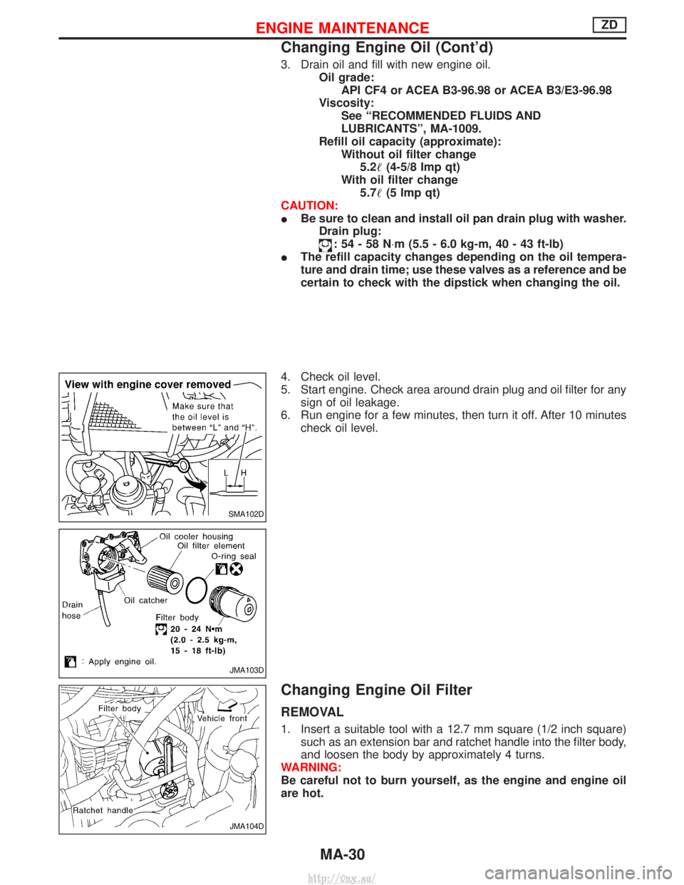
4. Check oil level.
5. Start engine. Check area around drain plug and oil filter for any sign of oil leakage.
6. Run engine for a few minutes, then turn it off. After 10 minutes check oil level.
Changing Engine Oil Filter
REMOVAL
1. Insert a suitable tool with a 12.7 mm square (1/2 inch square)such as an extension bar and ratchet handle into the filter body,
and loosen the body by approximately 4 turns.
WARNING:
Be careful not to burn yourself, as the engine and engine oil
are hot.
SMA102D
JMA103D
JMA104D
ENGINE MAINTENANCEZD
Changing Engine Oil (Cont'd)
MA-30
http://vnx.su/
Page 72 of 1833
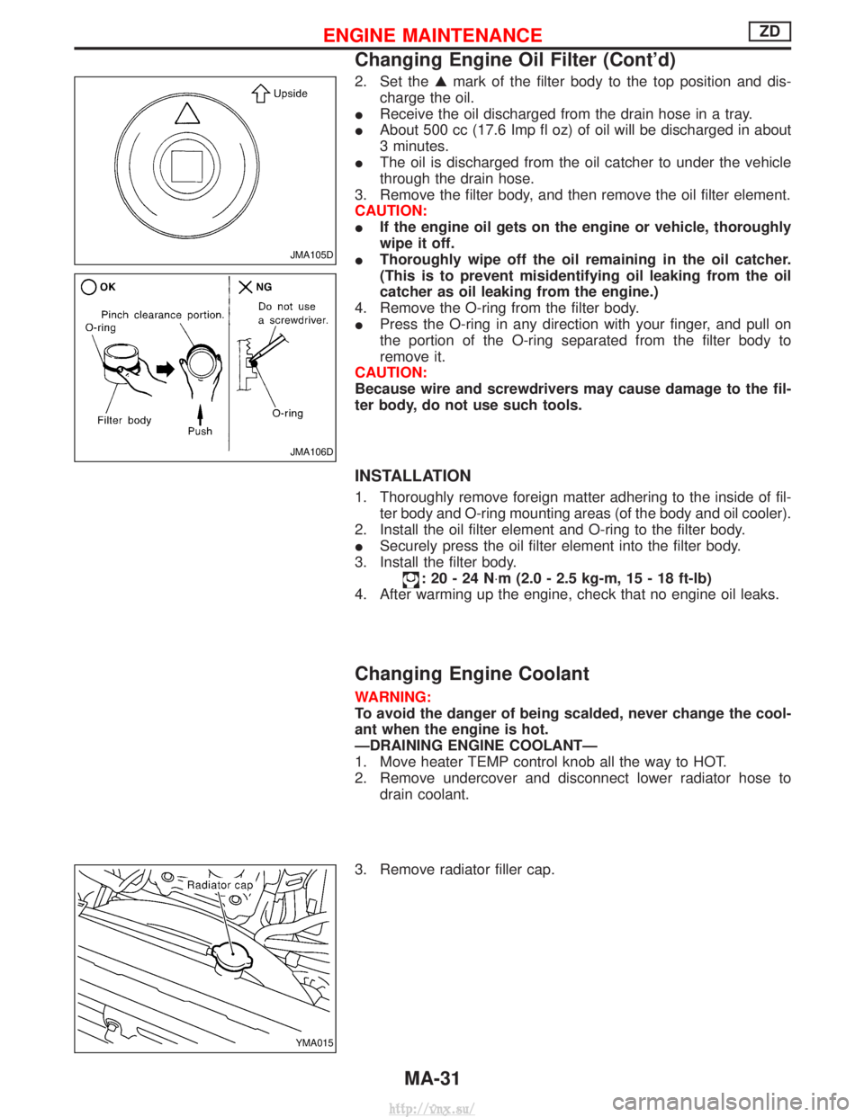
2. Set theGmark of the filter body to the top position and dis-
charge the oil.
I Receive the oil discharged from the drain hose in a tray.
I About 500 cc (17.6 Imp fl oz) of oil will be discharged in about
3 minutes.
I The oil is discharged from the oil catcher to under the vehicle
through the drain hose.
3. Remove the filter body, and then remove the oil filter element.
CAUTION:
I If the engine oil gets on the engine or vehicle, thoroughly
wipe it off.
I Thoroughly wipe off the oil remaining in the oil catcher.
(This is to prevent misidentifying oil leaking from the oil
catcher as oil leaking from the engine.)
4. Remove the O-ring from the filter body.
I Press the O-ring in any direction with your finger, and pull on
the portion of the O-ring separated from the filter body to
remove it.
CAUTION:
Because wire and screwdrivers may cause damage to the fil-
ter body, do not use such tools.
INSTALLATION
1. Thoroughly remove foreign matter adhering to the inside of fil- ter body and O-ring mounting areas (of the body and oil cooler).
2. Install the oil filter element and O-ring to the filter body.
I Securely press the oil filter element into the filter body.
3. Install the filter body.
:20-24N ×m (2.0 - 2.5 kg-m, 15 - 18 ft-lb)
4. After warming up the engine, check that no engine oil leaks.
Changing Engine Coolant
WARNING:
To avoid the danger of being scalded, never change the cool-
ant when the engine is hot.
ÐDRAINING ENGINE COOLANTÐ
1. Move heater TEMP control knob all the way to HOT.
2. Remove undercover and disconnect lower radiator hose to drain coolant.
3. Remove radiator filler cap.
JMA105D
JMA106D
YMA015
ENGINE MAINTENANCEZD
Changing Engine Oil Filter (Cont'd)
MA-31
http://vnx.su/
Page 155 of 1833

Engine room (Left)
3. Remove air duct and air cleaner case.
4. Disconnect vacuum hose to the vehicle on the engine.
5. Disconnect harness connectors from alternator and air com-pressor.
6. Remove alternator.
7. After removing refrigerant, remove pipes of air compressor and inlet/outlet.
8. Disconnect heating hose, install blank cap to hose to prevent coolant from leaking.
9. Remove heating pipe.
10. Remove heat insulator.
11. Remove catalytic converter.
Engine room (Right)
12. Remove power steering reservoir tank from bracket, and fix it to the vehicle with a rope.
CAUTION:
Keep the reservoir tank level when fixing to prevent oil leak.
13. Remove fuel feed and return hoses.
CAUTION:
Install blank caps immediately to avoid fuel leakage.
14. Remove all harness connectors on the engine, and move har- nesses to the side of the vehicle.
Vehicle underfloor
15. Remove starter motor.
16. Detach A/T oil cooler pipes from oil pan. (A/T model)
17. Remove rear propeller shaft.
18. Remove mounting bolts to secure the engine to transmission.
1) Remove torque converter installation bolt. (A/T model)
2) Lift transmission bottom with transmission jack, and removerear mount members from the vehicle.
3) Lower transmission with the jack, and remove upper mounting bolts securing the engine to transmission.
4) Lift transmission with the jack, and reinstall rear mount mem- bers to the vehicle.
5) Position the jack to the front side of transmission.
6) Remove remaining mounting bolts securing the engine to trans- mission.
Removal operation
19. Remove air conditioner high pressure pipes at the rear of theengine room.
I This is due to some inconvenience in the rear slinger installa-
tion.
20. Install the engine slingers (standard service part) to front-left and rear-right.
:25-28N ×m (2.5 - 2.9 kg-m, 18 - 20 ft-lb)
WARNING:
For engines without engine slingers, attach proper slingers
and bolts described in the PARTS CATALOG.
FEM082
ENGINE REMOVALZD
Removal (Cont'd)
EM-64
http://vnx.su/
Page 199 of 1833

3. Press service valve guide into cylinder head using suitable tooluntil the guide projects out 16 0.2 mm (0.63 0.008 in).
4. Ream valve guide. Finished size:8.000 - 8.015 mm (0.3150 - 0.3156 in)
VALVE SEATS
Check valve for any evidence of pitting at valve contact surface,
and reseat or replace if worn out excessively.
IWhen repairing valve seats, check valve and valve guide
for wear beforehand. If worn, replace them. Then correct
valve seat.
I The cutting should be done with both hands for uniform
cutting.
REPLACING VALVE SEAT FOR SERVICE PARTS
1. Before out old seat until it collapses or remove valve seats with
Tool.
Place a copper seat between contact surface of Tool and cyl-
inder head.
2. Place new valve seats on dry ice and allow them to cool for five minutes.
WARNING:
Do not touch cooled valve seats with bare hand.
3. Heat cylinder head to 80ÉC (176ÉF).
4. Install cooled valve seats on cylinder head with Tool.
NEM178
SEM630B
SEM024
SEM631B
SEM632B
CYLINDER HEADTD27Ti
Inspection (Cont'd)
EM-108
http://vnx.su/
Page 200 of 1833
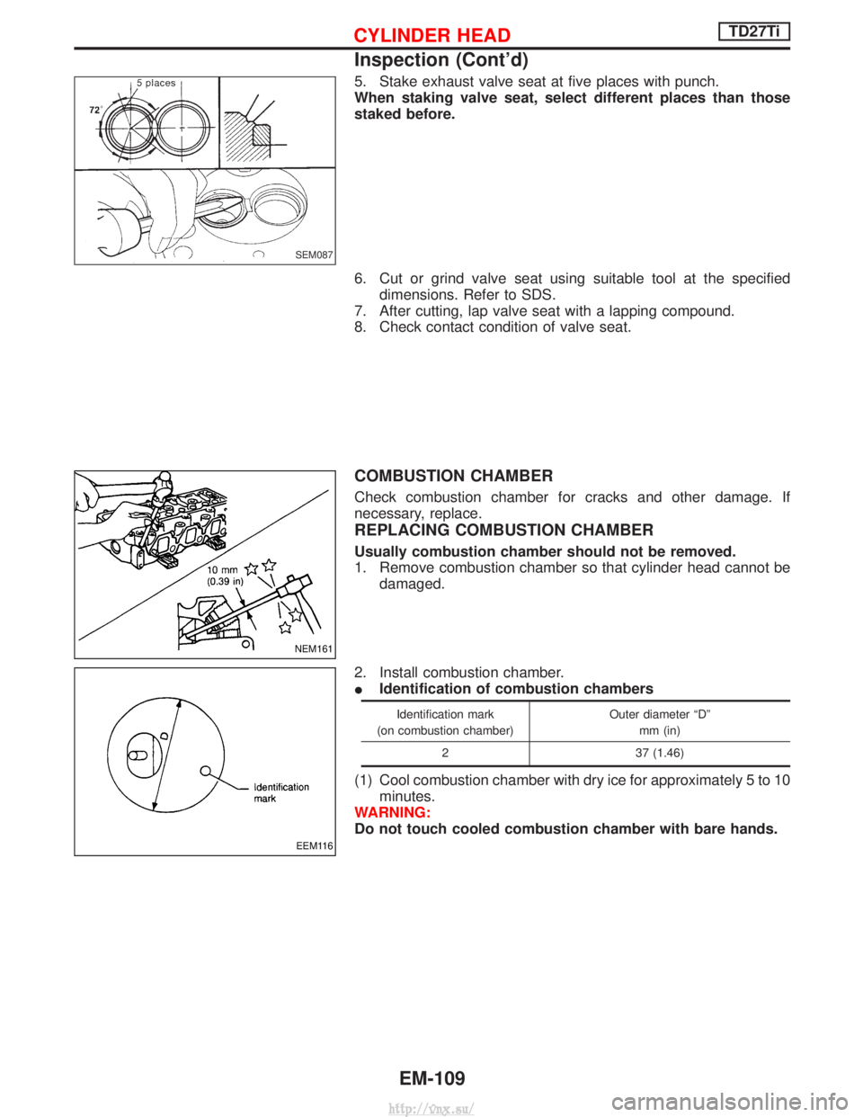
5. Stake exhaust valve seat at five places with punch.
When staking valve seat, select different places than those
staked before.
6. Cut or grind valve seat using suitable tool at the specifieddimensions. Refer to SDS.
7. After cutting, lap valve seat with a lapping compound.
8. Check contact condition of valve seat.
COMBUSTION CHAMBER
Check combustion chamber for cracks and other damage. If
necessary, replace.
REPLACING COMBUSTION CHAMBER
Usually combustion chamber should not be removed.
1. Remove combustion chamber so that cylinder head cannot be damaged.
2. Install combustion chamber.
I Identification of combustion chambers
Identification mark
(on combustion chamber) Outer diameter ªDº
mm (in)
2 37 (1.46)
(1) Cool combustion chamber with dry ice for approximately 5 to 10 minutes.
WARNING:
Do not touch cooled combustion chamber with bare hands.
SEM087
NEM161
EEM116
CYLINDER HEADTD27Ti
Inspection (Cont'd)
EM-109
http://vnx.su/