2004 NISSAN TERRANO air condition
[x] Cancel search: air conditionPage 89 of 1833
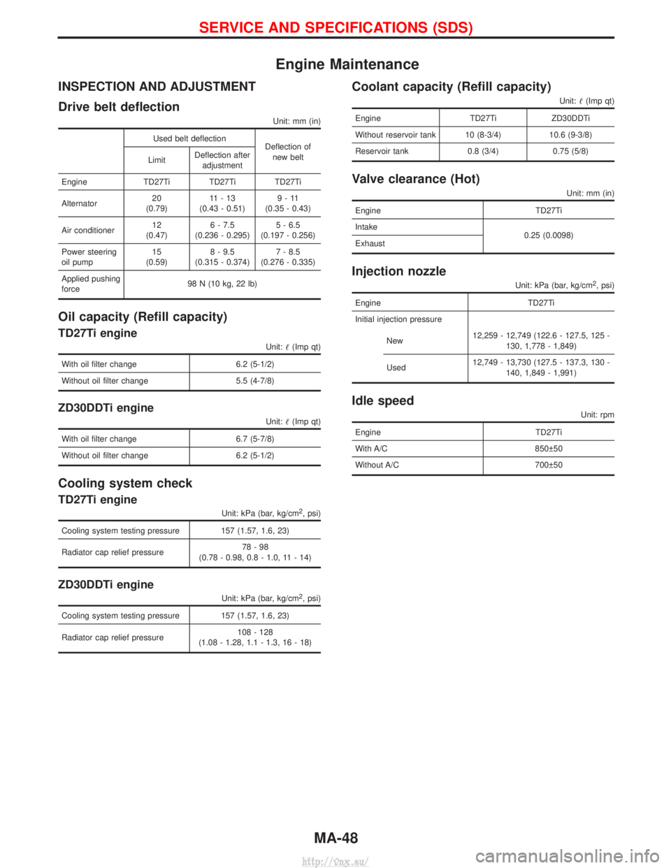
Engine Maintenance
INSPECTION AND ADJUSTMENT
Drive belt deflection
Unit: mm (in)
Used belt deflectionDeflection of
new belt
Limit Deflection after
adjustment
Engine TD27Ti TD27Ti TD27Ti
Alternator 20
(0.79) 11-13
(0.43 - 0.51) 9-11
(0.35 - 0.43)
Air conditioner 12
(0.47) 6 - 7.5
(0.236 - 0.295) 5 - 6.5
(0.197 - 0.256)
Power steering
oil pump 15
(0.59) 8 - 9.5
(0.315 - 0.374) 7 - 8.5
(0.276 - 0.335)
Applied pushing
force 98 N (10 kg, 22 lb)
Oil capacity (Refill capacity)
TD27Ti engine
Unit:
(Imp qt)
With oil filter change 6.2 (5-1/2)
Without oil filter change 5.5 (4-7/8)
ZD30DDTi engine
Unit: (Imp qt)
With oil filter change 6.7 (5-7/8)
Without oil filter change 6.2 (5-1/2)
Cooling system check
TD27Ti engine
Unit: kPa (bar, kg/cm2, psi)
Cooling system testing pressure 157 (1.57, 1.6, 23)
Radiator cap relief pressure 78-98
(0.78 - 0.98, 0.8 - 1.0, 11 - 14)
ZD30DDTi engine
Unit: kPa (bar, kg/cm2, psi)
Cooling system testing pressure 157 (1.57, 1.6, 23)
Radiator cap relief pressure 108 - 128
(1.08 - 1.28, 1.1 - 1.3, 16 - 18)
Coolant capacity (Refill capacity)
Unit: (Imp qt)
Engine TD27TiZD30DDTi
Without reservoir tank 10 (8-3/4) 10.6 (9-3/8)
Reservoir tank 0.8 (3/4) 0.75 (5/8)
Valve clearance (Hot)
Unit: mm (in)
Engine TD27Ti
Intake 0.25 (0.0098)
Exhaust
Injection nozzle
Unit: kPa (bar, kg/cm2, psi)
Engine TD27Ti
Initial injection pressure
New 12,259 - 12,749 (122.6 - 127.5, 125 -
130, 1,778 - 1,849)
Used 12,749 - 13,730 (127.5 - 137.3, 130 -
140, 1,849 - 1,991)
Idle speed
Unit: rpm
Engine TD27Ti
With A/C 850 50
Without A/C 700 50
SERVICE AND SPECIFICATIONS (SDS)
MA-48
http://vnx.su/
Page 100 of 1833
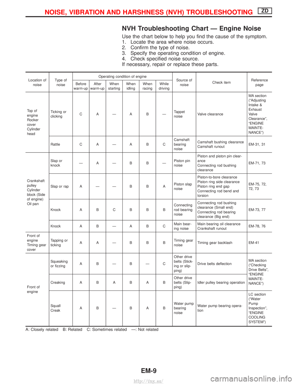
NVH Troubleshooting Chart Ð Engine Noise
Use the chart below to help you find the cause of the symptom.
1. Locate the area where noise occurs.
2. Confirm the type of noise.
3. Specify the operating condition of engine.
4. Check specified noise source.
If necessary, repair or replace these parts.
Location ofnoise Type of
noise Operating condition of engine
Source of
noise Check item Reference
page
Before
warm-up After
warm-up When
starting When
idling When
racing While
driving
To p o f
engine
Rocker
cover
Cylinder
head Ticking or
clicking
C AÐA BÐ Tappet
noiseValve clearance MA section
(ªAdjusting
Intake &
Exhaust
Valve
Clearanceº,
ªENGINE
MAINTE-
NANCEº)
Rattle C A Ð A B C Camshaft
bearing
noiseCamshaft bushing clearance
Camshaft runout
EM-31, 31
Crankshaft
pulley
Cylinder
block (Side
of engine)
Oil pan Slap or
knock
ÐAÐB BÐ Piston pin
noisePiston and piston pin clear-
ance
Connecting rod bushing
clearance
EM-71, 73
Slap or rap A Ð Ð B B A Piston slap
noisePiston-to-bore clearance
Piston ring side clearance
Piston ring end gap
Connecting rod bend and
torsion EM-75, 72,
72, 73
Knock A B C B B B Connecting
rod bearing
noiseConnecting rod bushing
clearance (Small end)
Connecting rod bearing
clearance (Big end)
EM-73, 77
Knock A B Ð A B C Main bear-
ing noiseMain bearing oil clearance
Crankshaft runout
EM-78, 76
Front of
engine
Timing gear
cover Tapping or
ticking
AAÐBBB Timing gear
noiseTiming gear backlash EM-41
Front of
engine Squeaking
or fizzing
A BÐBÐC Other drive
belts (Stick-
ing or slip-
ping)Drive belts deflection
MA section
(ªChecking
Drive Beltsº,
ªENGINE
MAINTE-
NANCEº)
Creaking
ABABAB Other drive
belts (Slip-
ping)Idler pulley bearing operation
Squall
Creak ABÐBAB Water pump
bearing
noiseWater pump bearing opera-
tion LC section
(ªWater
Pump
Inspectionº,
ªENGINE
COOLING
SYSTEMº)
A: Closely related B: Related C: Sometimes related Ð: Not related
NOISE, VIBRATION AND HARSHNESS (NVH) TROUBLESHOOTINGZD
EM-9
http://vnx.su/
Page 130 of 1833
Removal
1. Remove the engine assembly.Refer to ªENGINE REMOVALº, EM-63.
2. Place the engine on an engine stand (SST). Refer to ªCYLINDER BLOCKº, EM-67.
3. Remove the following.
I Auto tensioner bracket
I Air conditioner bracket
I Alternator bracket
I Oil tube
I Vacuum pump
I Rocker cover
I Oil pan (upper, lower)
I Injection tube
I Spill tube
I High pressure nozzle assembly
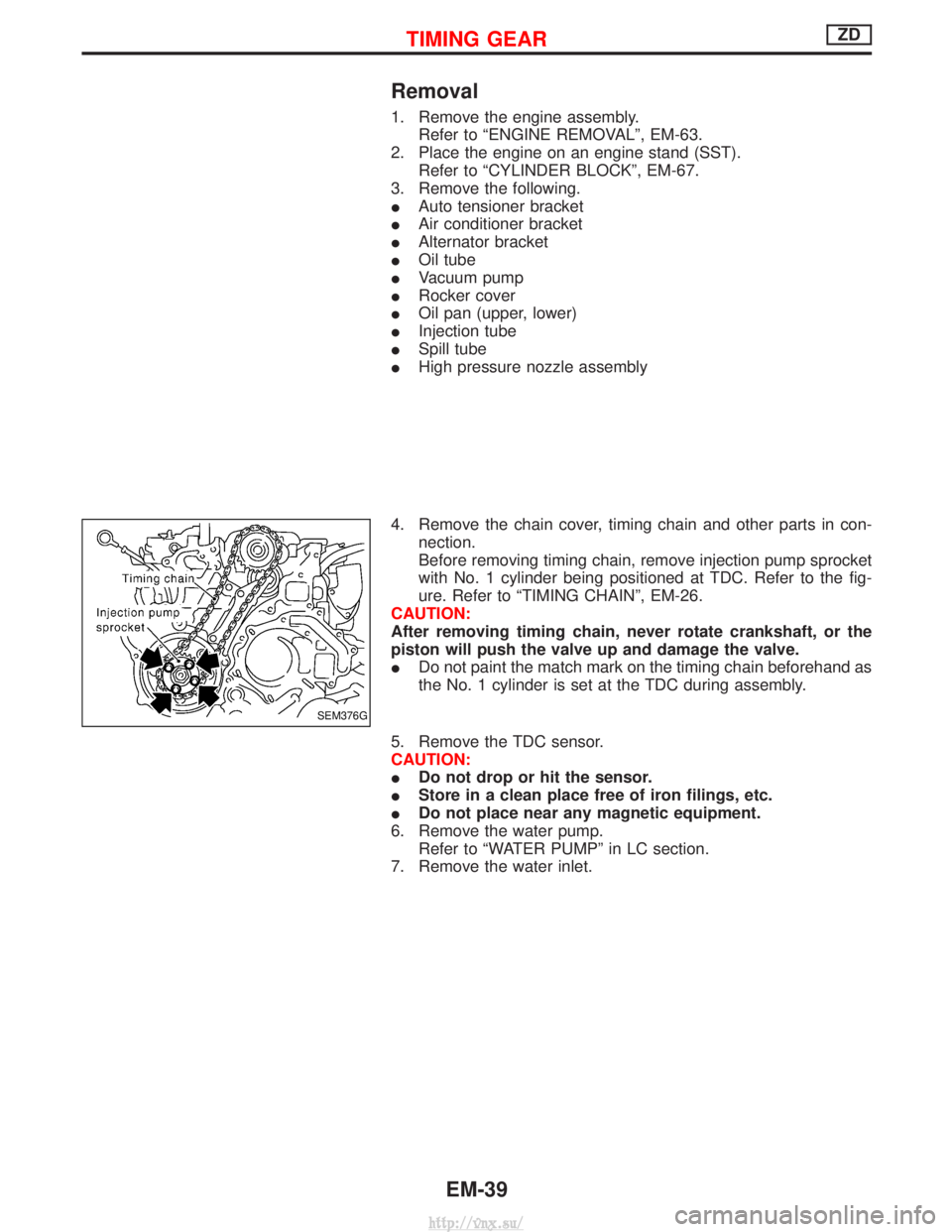
4. Remove the chain cover, timing chain and other parts in con- nection.
Before removing timing chain, remove injection pump sprocket
with No. 1 cylinder being positioned at TDC. Refer to the fig-
ure. Refer to ªTIMING CHAINº, EM-26.
CAUTION:
After removing timing chain, never rotate crankshaft, or the
piston will push the valve up and damage the valve.
I Do not paint the match mark on the timing chain beforehand as
the No. 1 cylinder is set at the TDC during assembly.
5. Remove the TDC sensor.
CAUTION:
I Do not drop or hit the sensor.
I Store in a clean place free of iron filings, etc.
I Do not place near any magnetic equipment.
6. Remove the water pump. Refer to ªWATER PUMPº in LC section.
7. Remove the water inlet.
SEM376G
TIMING GEARZD
EM-39
http://vnx.su/
Page 155 of 1833

Engine room (Left)
3. Remove air duct and air cleaner case.
4. Disconnect vacuum hose to the vehicle on the engine.
5. Disconnect harness connectors from alternator and air com-pressor.
6. Remove alternator.
7. After removing refrigerant, remove pipes of air compressor and inlet/outlet.
8. Disconnect heating hose, install blank cap to hose to prevent coolant from leaking.
9. Remove heating pipe.
10. Remove heat insulator.
11. Remove catalytic converter.
Engine room (Right)
12. Remove power steering reservoir tank from bracket, and fix it to the vehicle with a rope.
CAUTION:
Keep the reservoir tank level when fixing to prevent oil leak.
13. Remove fuel feed and return hoses.
CAUTION:
Install blank caps immediately to avoid fuel leakage.
14. Remove all harness connectors on the engine, and move har- nesses to the side of the vehicle.
Vehicle underfloor
15. Remove starter motor.
16. Detach A/T oil cooler pipes from oil pan. (A/T model)
17. Remove rear propeller shaft.
18. Remove mounting bolts to secure the engine to transmission.
1) Remove torque converter installation bolt. (A/T model)
2) Lift transmission bottom with transmission jack, and removerear mount members from the vehicle.
3) Lower transmission with the jack, and remove upper mounting bolts securing the engine to transmission.
4) Lift transmission with the jack, and reinstall rear mount mem- bers to the vehicle.
5) Position the jack to the front side of transmission.
6) Remove remaining mounting bolts securing the engine to trans- mission.
Removal operation
19. Remove air conditioner high pressure pipes at the rear of theengine room.
I This is due to some inconvenience in the rear slinger installa-
tion.
20. Install the engine slingers (standard service part) to front-left and rear-right.
:25-28N ×m (2.5 - 2.9 kg-m, 18 - 20 ft-lb)
WARNING:
For engines without engine slingers, attach proper slingers
and bolts described in the PARTS CATALOG.
FEM082
ENGINE REMOVALZD
Removal (Cont'd)
EM-64
http://vnx.su/
Page 191 of 1833
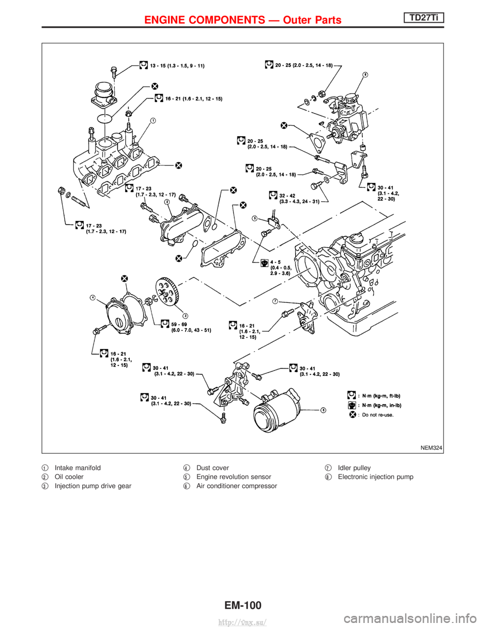
q1Intake manifold
q
2Oil cooler
q
3Injection pump drive gear q
4Dust cover
q
5Engine revolution sensor
q
6Air conditioner compressor q
7Idler pulley
q
8Electronic injection pump
NEM324
ENGINE COMPONENTS Ð Outer PartsTD27Ti
EM-100
http://vnx.su/
Page 210 of 1833
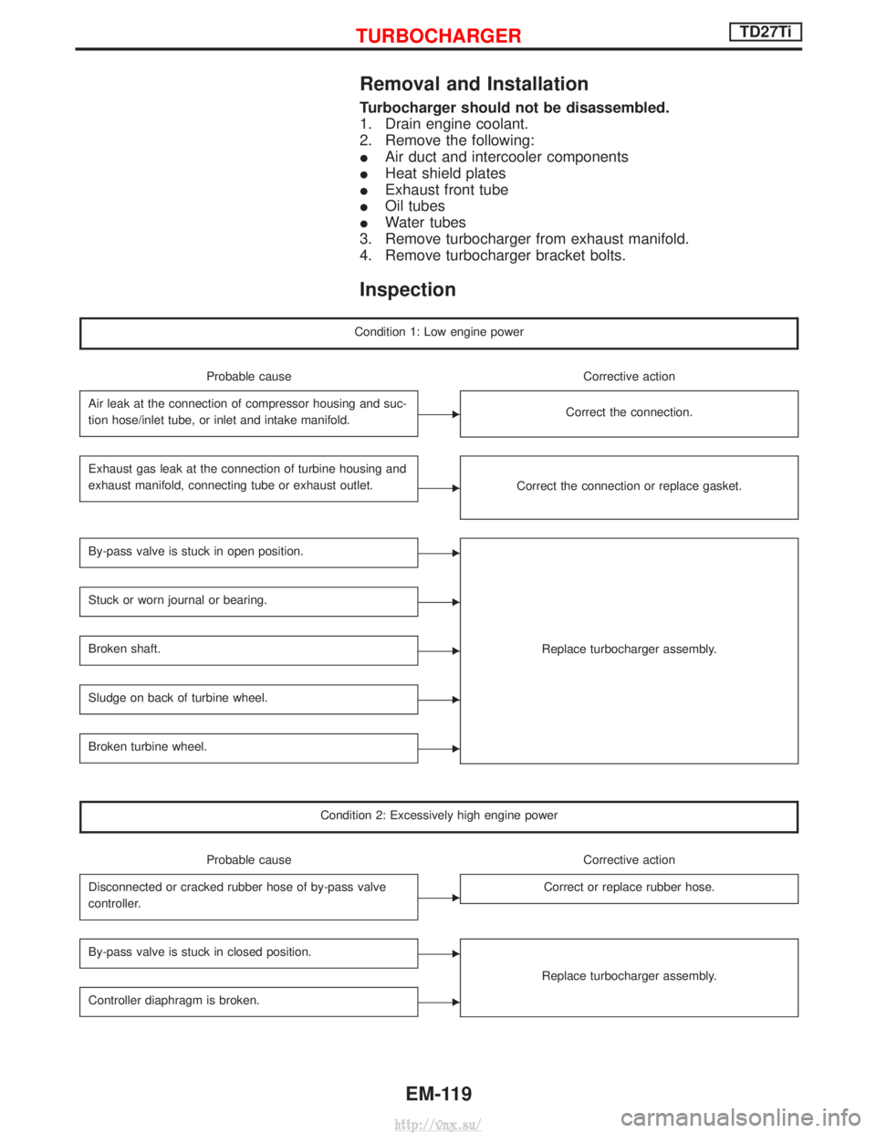
Removal and Installation
Turbocharger should not be disassembled.
1. Drain engine coolant.
2. Remove the following:
IAir duct and intercooler components
I Heat shield plates
I Exhaust front tube
I Oil tubes
I Water tubes
3. Remove turbocharger from exhaust manifold.
4. Remove turbocharger bracket bolts.
Inspection
Condition 1: Low engine power
Probable cause Corrective action
Air leak at the connection of compressor housing and suc-
tion hose/inlet tube, or inlet and intake manifold.
ECorrect the connection.
Exhaust gas leak at the connection of turbine housing and
exhaust manifold, connecting tube or exhaust outlet.
ECorrect the connection or replace gasket.
By-pass valve is stuck in open position.E
Replace turbocharger assembly.
Stuck or worn journal or bearing.E
Broken shaft.E
Sludge on back of turbine wheel.E
Broken turbine wheel.E
Condition 2: Excessively high engine power
Probable cause Corrective action
Disconnected or cracked rubber hose of by-pass valve
controller.
ECorrect or replace rubber hose.
By-pass valve is stuck in closed position.E
Replace turbocharger assembly.
Controller diaphragm is broken.E
TURBOCHARGERTD27Ti
EM-119
http://vnx.su/
Page 254 of 1833
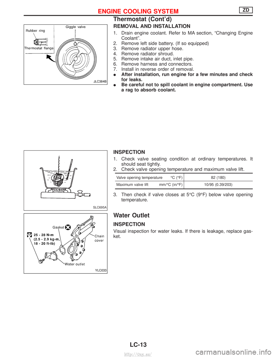
REMOVAL AND INSTALLATION
1. Drain engine coolant. Refer to MA section, ªChanging EngineCoolantº.
2. Remove left side battery. (If so equipped)
3. Remove radiator upper hose.
4. Remove radiator shroud.
5. Remove intake air duct, inlet pipe.
6. Remove harness and connectors.
7. Install in reverse order of removal.
I After installation, run engine for a few minutes and check
for leaks.
I Be careful not to spill coolant in engine compartment. Use
a rag to absorb coolant.
INSPECTION
1. Check valve seating condition at ordinary temperatures. It
should seat tightly.
2. Check valve opening temperature and maximum valve lift.
Valve opening temperature ÉC (ÉF) 82 (180)
Maximum valve lift mm/ÉC (in/ÉF) 10/95 (0.39/203)
3. Then check if valve closes at 5ÉC (9ÉF) below valve opening
temperature.
Water Outlet
INSPECTION
Visual inspection for water leaks. If there is leakage, replace gas-
ket.
JLC384B
SLC695A
YLC033
ENGINE COOLING SYSTEMZD
Thermostat (Cont'd)
LC-13
http://vnx.su/
Page 276 of 1833
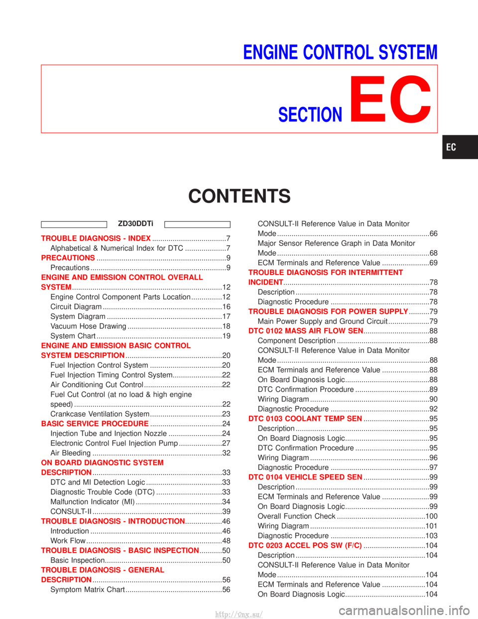
ENGINE CONTROL SYSTEMSECTION
EC
CONTENTS
ZD30DDTi
TROUBLE DIAGNOSIS - INDEX ....................................7
Alphabetical & Numerical Index for DTC ....................7
PRECAUTIONS ...............................................................9
Precautions ..................................................................9
ENGINE AND EMISSION CONTROL OVERALL
SYSTEM ........................................................................\
.12
Engine Control Component Parts Location ...............12
Circuit Diagram ..........................................................16
System Diagram ........................................................17
Vacuum Hose Drawing ..............................................18
System Chart .............................................................19
ENGINE AND EMISSION BASIC CONTROL
SYSTEM DESCRIPTION ...............................................20
Fuel Injection Control System ...................................20
Fuel Injection Timing Control System........................22
Air Conditioning Cut Control ......................................22
Fuel Cut Control (at no load & high engine
speed) ........................................................................\
22
Crankcase Ventilation System ...................................23
BASIC SERVICE PROCEDURE ...................................24
Injection Tube and Injection Nozzle ..........................24
Electronic Control Fuel Injection Pump .....................27
Air Bleeding ...............................................................32
ON BOARD DIAGNOSTIC SYSTEM
DESCRIPTION ...............................................................33
DTC and MI Detection Logic .....................................33
Diagnostic Trouble Code (DTC) ................................33
Malfunction Indicator (MI) ..........................................34
CONSULT-II ...............................................................39
TROUBLE DIAGNOSIS - INTRODUCTION ..................46
Introduction ................................................................46
Work Flow ..................................................................48
TROUBLE DIAGNOSIS - BASIC INSPECTION ...........50
Basic Inspection.........................................................50
TROUBLE DIAGNOSIS - GENERAL
DESCRIPTION ...............................................................56
Symptom Matrix Chart ...............................................56 CONSULT-II Reference Value in Data Monitor
Mode ........................................................................\
..66
Major Sensor Reference Graph in Data Monitor
Mode ........................................................................\
..68
ECM Terminals and Reference Value .......................69
TROUBLE DIAGNOSIS FOR INTERMITTENT
INCIDENT .......................................................................78
Description .................................................................78
Diagnostic Procedure ................................................78
TROUBLE DIAGNOSIS FOR POWER SUPPLY ..........79
Main Power Supply and Ground Circuit ....................79
DTC 0102 MASS AIR FLOW SEN ................................88
Component Description .............................................88
CONSULT-II Reference Value in Data Monitor
Mode ........................................................................\
..88
ECM Terminals and Reference Value .......................88
On Board Diagnosis Logic.........................................88
DTC Confirmation Procedure ....................................89
Wiring Diagram ..........................................................90
Diagnostic Procedure ................................................92
DTC 0103 COOLANT TEMP SEN ................................95
Description .................................................................95
On Board Diagnosis Logic.........................................95
DTC Confirmation Procedure ....................................95
Wiring Diagram ..........................................................96
Diagnostic Procedure ................................................97
DTC 0104 VEHICLE SPEED SEN ................................99
Description .................................................................99
ECM Terminals and Reference Value .......................99
On Board Diagnosis Logic.........................................99
Overall Function Check ...........................................100
Wiring Diagram ........................................................101
Diagnostic Procedure ..............................................103
DTC 0203 ACCEL POS SW (F/C) ..............................104
Description ...............................................................104
CONSULT-II Reference Value in Data Monitor
Mode ........................................................................\
104
ECM Terminals and Reference Value .....................104
On Board Diagnosis Logic.......................................104
http://vnx.su/