2004 NISSAN TERRANO air condition
[x] Cancel search: air conditionPage 1539 of 1833
Trouble Diagnoses
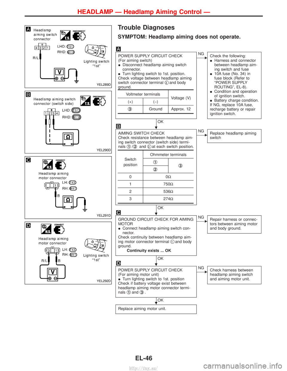
SYMPTOM: Headlamp aiming does not operate.
POWER SUPPLY CIRCUIT CHECK
(For aiming switch)
IDisconnect headlamp aiming switch
connector.
I Turn lighting switch to 1st. position.
Check voltage between headlamp aiming
switch connector terminal q
3and body
ground.
OK
ENG Check the following:
IHarness and connector
between headlamp aim-
ing switch and fuse
I 10A fuse (No. 34) in
fuse block (Refer to
ªPOWER SUPPLY
ROUTINGº, EL-8).
I Condition and operation
of ignition switch.
I Battery charge condition.
If NG, replace 10A fuse,
recharge battery or repair
ignition switch.
AIMING SWITCH CHECK
Check resistance between headlamp aim-
ing switch connector (switch side) termi-
nals q
1/q2and q3at each switch position.
OK
ENG
Replace headlamp aiming
switch
GROUND CIRCUIT CHECK FOR AIMING
MOTOR
IConnect headlamp aiming switch con-
nector.
Check continuity between headlamp aim-
ing motor connector terminal q
1and body
ground. Continuity exists ... OK
OK
ENG Repair harness or connec-
tors between aiming motor
and body ground.
POWER SUPPLY CIRCUIT CHECK
(For aiming motor unit)
ITurn lighting switch to 1st. position
Check if battery voltage exist between
headlamp aiming motor connector termi-
nals q
1andq3.
OK
ENG
Check harness between
headlamp aiming switch
and aiming motor unit.
Replace aiming motor unit.
Voltmeter terminals
Voltage (V)
(+) (þ)
q
3Ground Approx. 12
Switch
position Ohmmeter terminals
q1q3q2
00 W
1 750W
2 536W
3 274W
YEL289D
YEL290D
YEL291D
YEL292D
H
H
H
H
HEADLAMP Ð Headlamp Aiming Control Ð
EL-46
http://vnx.su/
Page 1584 of 1833

Check itemsDisplay Remarks
I) Fuel warning lamp test
SEL443X
Fuel warning lamp is on and odo trip meter segment ªFUELº
flashes.
Failure Chart for ªError 1º and ªError Eº
Bit Detectable items Description of the failureDisplayed figure on the
bit
Failure No failure
0 Speedometer input
signal
No input signal
When no signal is detected for 30 minutes continuously with
the ignition ON, it should be judged as signal failure.
(If input signal is detected later, then the judgement will be
canceled immediately.) 1
0
Abnormal input signal
When any signal of frequency which would not exist in normal
conditions is detected, it should be judged as signal failure. 2
1 Tachometer input
signal
No input signal
When no signal is detected for 30 minutes continuously with
the ignition ON, it should be judged as signal failure.
(If input signal is detected later, then the judgement will be
canceled immediately.) 1
0
Abnormal input signal
When any signal of frequency which would not exist in normal
conditions is detected, it should be judged as signal failure. 2
2 Fuel level input sig-
nal
Short circuit
When short circuit of the signal line is detected for 5 seconds
or more, it should be judged as short-circuit failure. 1
0
Open circuit
When open circuit of the signal line is detected for 5 seconds
or more, it should be judged as open-circuit failure. 2
3 Water temperature
input signal Short circuit
When short circuit of the signal line is detected for 5 seconds
or more, it should be judged as short-circuit failure. 10
4 Outside air tempera-
ture input signal
Short circuit
When short circuit of the signal line is detected for 5 seconds
or more, it should be judged as short-circuit failure. 1
0
Open circuit
When open circuit of the signal line is detected for 5 seconds
or more, it should be judged as open-circuit failure. 2
5 Reset buttons Short circuit for reset buttons
When the short circuit is continu-
ously detected for 5 minutes or
more, it should be judged as
short-circuit failure. Right side reset button has
failed.
1
0
Left side reset button has
failed. 2
Both reset buttons have
failed. 3
6Ð Ð 00
7 CPU EEPROM failure 1
0
CPU RAM failure 2
METER AND GAUGES
Combination Meter Self-Diagnosis (Cont'd)
EL-91
http://vnx.su/
Page 1641 of 1833
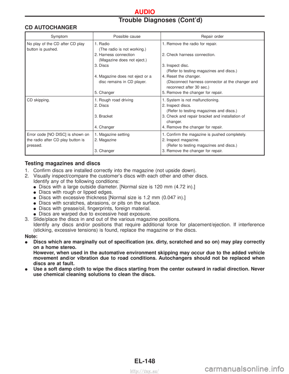
CD AUTOCHANGER
SymptomPossible cause Repair order
No play of the CD after CD play
button is pushed. 1. Radio
(The radio is not working.)
2. Harness connection (Magazine does not eject.)
3. Discs
4. Magazine does not eject or a disc remains in CD player.
5. Changer 1. Remove the radio for repair.
2. Check harness connection.
3. Inspect disc.
(Refer to testing magazines and discs.)
4. Reset the changer. (Disconnect harness connector at the changer and
reconnect after 30 sec.)
5. Remove the changer for repair.
CD skipping. 1. Rough road driving 2. Discs
3. Bracket
4. Changer1. System is not malfunctioning.
2. Inspect discs.
(Refer to testing magazines and discs.)
3. Check and repair bracket and installation of changer.
4. Remove the changer for repair.
Error code [NO DISC] is shown on
the radio after CD play button is
pressed. 1. Magazine setting
2. Magazine
3. Changer1. Confirm the magazine is pushed completely.
2. Inspect magazine.
(Refer to testing magazines and discs.)
3. Remove the changer for repair.
Testing magazines and discs
1. Confirm discs are installed correctly into the magazine (not upside down).
2. Visually inspect/compare the customer's discs with each other and other discs. Identify any of the following conditions:
IDiscs with a large outside diameter. [Normal size is 120 mm (4.72 in).]
I Discs with rough or lipped edges.
I Discs with excessive thickness [Normal size is 1.2 mm (0.047 in).]
I Discs with scratches, abrasions, or pits on the surface.
I Discs with grease/oil, fingerprints, foreign material.
I Discs are warped due to excessive heat exposure.
3. Slide/place the discs in and out of the various magazine positions. Identify any discs and/or positions that require additional force for placement/ejection. If interference
(sticking, excessive tensions) is found, replace the magazine or the discs.
Note:
I Discs which are marginally out of specification (ex. dirty, scratched and so on) may play correctly
on a home stereo.
However, when used in the automative environment skipping may occur due to the added vehicle
movement and/or vibration due to road conditions. Autochangers should not be replaced when
discs are at fault.
I Use a soft damp cloth to wipe the discs starting from the center outward in radial direction. Never
use chemical cleaning solutions to clean the discs.
AUDIO
Trouble Diagnoses (Cont'd)
EL-148
http://vnx.su/
Page 1693 of 1833
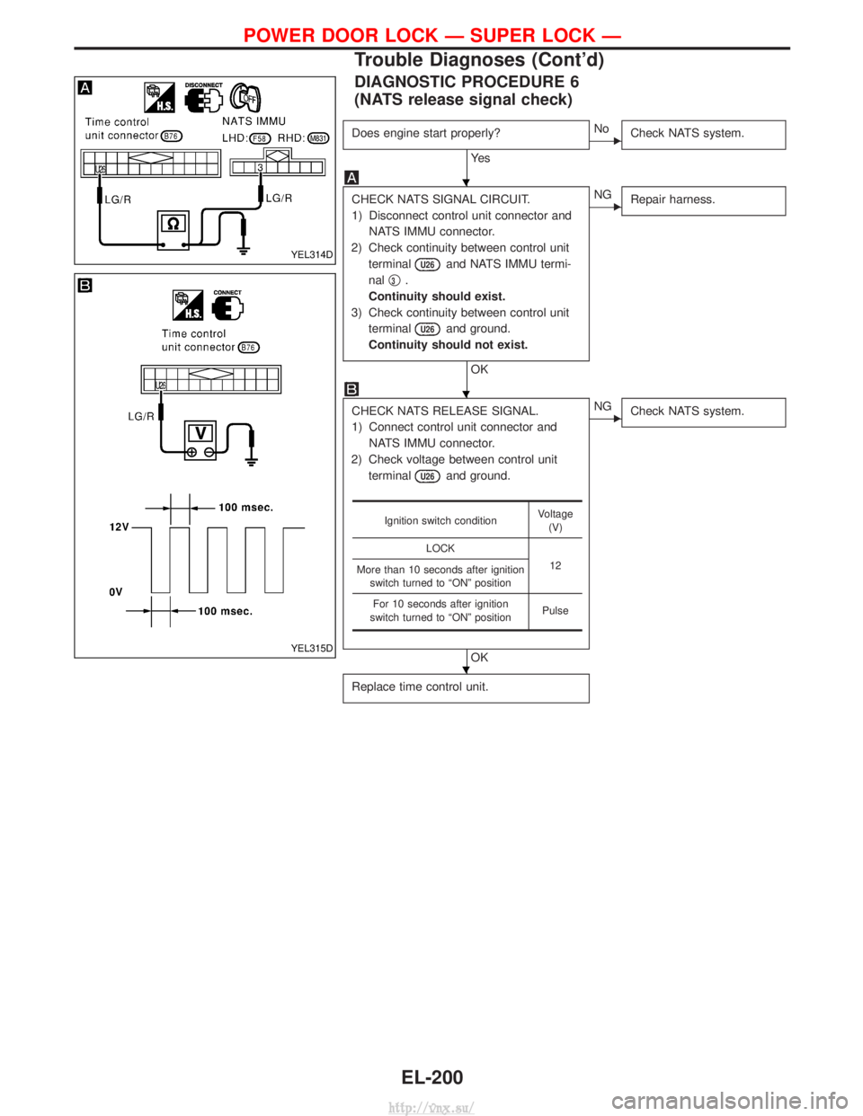
DIAGNOSTIC PROCEDURE 6
(NATS release signal check)
Does engine start properly?
Ye s
ENoCheck NATS system.
CHECK NATS SIGNAL CIRCUIT.
1) Disconnect control unit connector and
NATS IMMU connector.
2) Check continuity between control unit terminal
U26and NATS IMMU termi-
nal q
3.
Continuity should exist.
3) Check continuity between control unit terminal
U26and ground.
Continuity should not exist.
OK
ENG Repair harness.
CHECK NATS RELEASE SIGNAL.
1) Connect control unit connector and
NATS IMMU connector.
2) Check voltage between control unit terminal
U26and ground.
OK
ENG Check NATS system.
Replace time control unit.
Ignition switch condition Voltage
(V)
LOCK 12
More than 10 seconds after ignition
switch turned to ªONº position
For 10 seconds after ignition
switch turned to ªONº position Pulse
YEL314D
YEL315D
H
H
H
POWER DOOR LOCK Ð SUPER LOCK Ð
Trouble Diagnoses (Cont'd)
EL-200
http://vnx.su/
Page 1819 of 1833
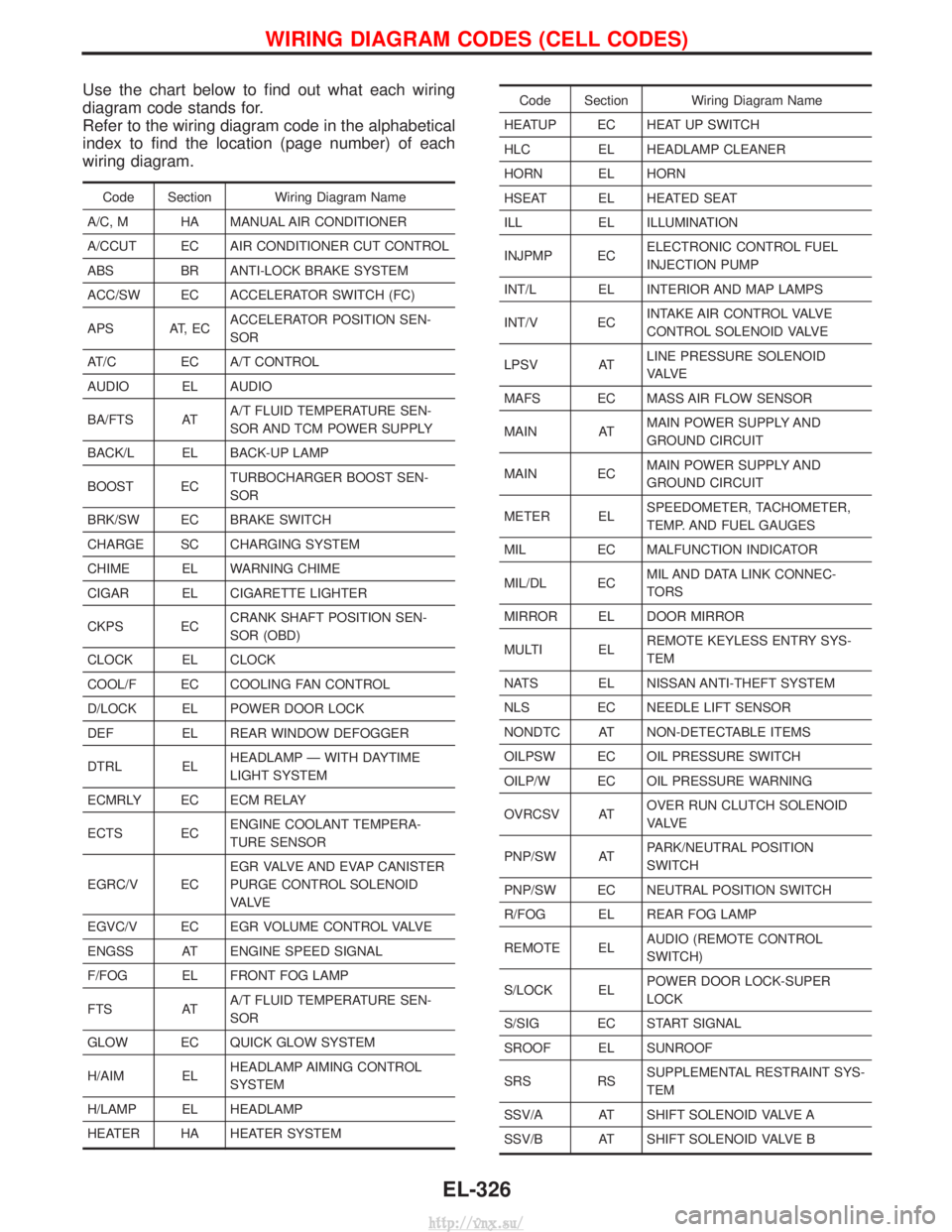
Use the chart below to find out what each wiring
diagram code stands for.
Refer to the wiring diagram code in the alphabetical
index to find the location (page number) of each
wiring diagram.
Code Section Wiring Diagram Name
A/C, M HA MANUAL AIR CONDITIONER
A/CCUT EC AIR CONDITIONER CUT CONTROL
ABS BR ANTI-LOCK BRAKE SYSTEM
ACC/SW EC ACCELERATOR SWITCH (FC)
APS AT, EC ACCELERATOR POSITION SEN-
SOR
AT/C EC A/T CONTROL
AUDIO EL AUDIO
BA/FTS AT A/T FLUID TEMPERATURE SEN-
SOR AND TCM POWER SUPPLY
BACK/L EL BACK-UP LAMP
BOOST EC TURBOCHARGER BOOST SEN-
SOR
BRK/SW EC BRAKE SWITCH
CHARGE SC CHARGING SYSTEM
CHIME EL WARNING CHIME
CIGAR EL CIGARETTE LIGHTER
CKPS EC CRANK SHAFT POSITION SEN-
SOR (OBD)
CLOCK EL CLOCK
COOL/F EC COOLING FAN CONTROL
D/LOCK EL POWER DOOR LOCK
DEF EL REAR WINDOW DEFOGGER
DTRL EL HEADLAMP Ð WITH DAYTIME
LIGHT SYSTEM
ECMRLY EC ECM RELAY
ECTS EC ENGINE COOLANT TEMPERA-
TURE SENSOR
EGRC/V EC EGR VALVE AND EVAP CANISTER
PURGE CONTROL SOLENOID
VA LV E
EGVC/V EC EGR VOLUME CONTROL VALVE
ENGSS AT ENGINE SPEED SIGNAL
F/FOG EL FRONT FOG LAMP
FTS AT A/T FLUID TEMPERATURE SEN-
SOR
GLOW EC QUICK GLOW SYSTEM
H/AIM EL HEADLAMP AIMING CONTROL
SYSTEM
H/LAMP EL HEADLAMP
HEATER HA HEATER SYSTEM
Code Section Wiring Diagram Name
HEATUP EC HEAT UP SWITCH
HLC EL HEADLAMP CLEANER
HORN EL HORN
HSEAT EL HEATED SEAT
ILL EL ILLUMINATION
INJPMP EC ELECTRONIC CONTROL FUEL
INJECTION PUMP
INT/L EL INTERIOR AND MAP LAMPS
INT/V EC INTAKE AIR CONTROL VALVE
CONTROL SOLENOID VALVE
LPSV AT LINE PRESSURE SOLENOID
VA LV E
MAFS EC MASS AIR FLOW SENSOR
MAIN AT MAIN POWER SUPPLY AND
GROUND CIRCUIT
MAIN EC MAIN POWER SUPPLY AND
GROUND CIRCUIT
METER EL SPEEDOMETER, TACHOMETER,
TEMP. AND FUEL GAUGES
MIL EC MALFUNCTION INDICATOR
MIL/DL EC MIL AND DATA LINK CONNEC-
TORS
MIRROR EL DOOR MIRROR
MULTI EL REMOTE KEYLESS ENTRY SYS-
TEM
NATS EL NISSAN ANTI-THEFT SYSTEM
NLS EC NEEDLE LIFT SENSOR
NONDTC AT NON-DETECTABLE ITEMS
OILPSW EC OIL PRESSURE SWITCH
OILP/W EC OIL PRESSURE WARNING
OVRCSV AT OVER RUN CLUTCH SOLENOID
VA LV E
PNP/SW AT PARK/NEUTRAL POSITION
SWITCH
PNP/SW EC NEUTRAL POSITION SWITCH
R/FOG EL REAR FOG LAMP
REMOTE EL AUDIO (REMOTE CONTROL
SWITCH)
S/LOCK EL POWER DOOR LOCK-SUPER
LOCK
S/SIG EC START SIGNAL
SROOF EL SUNROOF
SRS RS SUPPLEMENTAL RESTRAINT SYS-
TEM
SSV/A AT SHIFT SOLENOID VALVE A
SSV/B AT SHIFT SOLENOID VALVE B
WIRING DIAGRAM CODES (CELL CODES)
EL-326
http://vnx.su/
Page 1827 of 1833
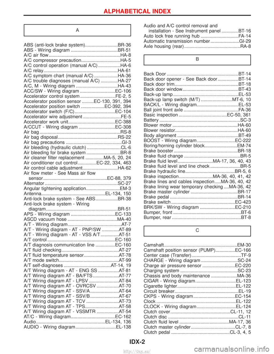
A
ABS (anti-lock brake system).........................BR-36
ABS - Wiring diagram ....................................BR-51
A/C air flow .......................................................HA-8
A/C compressor precaution..............................HA-5
A/C control operation (manual A/C) .................HA-6
A/C relay.........................................................HA-61
A/C symptom chart (manual A/C) ..................HA-36
A/C trouble diagnoses (manual A/C) .............HA-27
A/C, M - Wiring diagram ................................HA-43
ACC/SW - Wiring diagram ...........................EC-106
Accelerator control system ...........................FE-2, 5
Accelerator position sensor .........EC-130, 391, 394
Accelerator position switch ..................EC-392, 394
Accelerator switch (F/C) ...............................EC-104
Accelerator wire adjustment .............................FE-5
Accelerator work unit....................................EC-388
A/CCUT - Wiring diagram ............................EC-308
Air bag ..............................................................RS-8
Air bag disposal..............................................RS-22
Air bag precautions ...........................................GI-3
Air bleeding (hydraulic clutch) ..........................CL-6
Air bleeding for brake system ..........................BR-8
Air cleaner filter replacement ..............MA-5, 20, 24
Air conditioner cut control ..............EC-22, 334, 463
Air control cable adjustment...........................HA-62
Air flow meter - See Mass air flowsensor .................................................EC-88, 379
Alternator ........................................................SC-27
Angular tightening application..........................EM-3
Antenna.................................................EL-134, 150
Anti-lock brake system - See ABS .................BR-38
Anti-lock brake system - Wiring diagram .......................................................BR-51
APS - Wiring diagram ..................................EC-133
ASCD vacuum hose ......................................MA-40
A/T - Wiring diagram .........................................AT-7
A/T - Wiring diagram - AT - PNP/SW .............AT-89
A/T - Wiring diagram - AT - VSS A/T ..............AT-51
A/T control ....................................................EC-160
A/T diagnosis communication line ...............EC-160
A/T fluid checking ............................................AT-27
A/T fluid temperature sensor...........................AT-78
A/T mode switch..............................................AT-99
A/T self-diagnoses ....................................AT-14, 19
A/T Wiring diagram - AT - ENG SS ................AT-81
A/T Wiring diagram AT - BA/FTS ....................AT-77
A/T Wiring diagram AT - LPSV .......................AT-84
A/T Wiring diagram AT - OVRCSV .................AT-70
A/T Wiring diagram AT - SSV/A ......................AT-64
A/T Wiring diagram AT - SSV/B ......................AT-67
A/T Wiring diagram AT - TCV .........................AT-73
A/T Wiring diagram AT - TPS..........................AT-58
A/T Wiring diagram AT - VSSMTR .................AT-54
AT/C - Wiring diagram..................................EC-162
Audio .....................................................EL-134, 136
AUDIO - Wiring diagram ...............................EL-138 Audio and A/C control removal and
installation - See Instrument panel .............BT-16
Auto lock free running hub .............................FA-14
Automatic transmission number ......................GI-29
Axle housing (rear) ...........................................RA-8
B
Back Door .......................................................BT-14
Back door opener - See Back door ................BT-14
Back door trim.................................................BT-18
Back door window...........................................BT-43
Back-up lamp ..................................................EL-53
Back-up lamp switch (M/T) ........................MT-6, 10
BACK/L - Wiring diagram................................EL-53
Ball joint front axle ..........................................FA-36
Basic inspection .....................................EC-50, 361
Battery ..............................................................SC-3
Blower motor ..................................................HA-60
Blower resistor................................................HA-60
Body alignment ...............................................BT-49
BOOST - Wiring diagram .............................EC-222
Boring/horning cylinder block.........................EM-74
Brake booster .................................................BR-18
Brake fluid change ...........................................BR-5
Brake fluid level ...........................MA-17, 36, 40, 43
Brake fluid level and line check .......................BR-5
Brake hydraulic line......................................BR-5, 6
Brake inspection ..........................MA-36, 40, 41, 42
Brake lines and cables inspection.....MA-36, 40, 42
Brake lining wear temporary checking ....MA-36, 42
Brake master cylinder ....................................BR-17
Brake pedal ....................................................BR-14
Brake switch .................................................EC-423
BRK/SW - Wiring diagram ...........................EC-210
Bumper, front ....................................................BT-6
Bumper, rear .....................................................BT-8C
Camshaft ........................................................EM-30
Camshaft position sensor (PUMP)...............EC-166
Center case (Transfer) ......................................TF-9
CHARGE - Wiring diagram ............................SC-24
Charge air pressure sensor .........................EC-220
Charging system ............................................SC-23
Chassis and body maintenance ....................MA-36
CIGAR - Wiring diagram ...............................EL-123
Cigarette lighter.............................................EL-122
Circuit breaker.................................................EL-19
CKPS - Wiring diagram ................................EC-154
Clock .............................................................EL-122
CLOCK - Wiring diagram ..............................EL-124
Clutch cover ..............................................CL-11, 12
Clutch disc ......................................................CL-11
Clutch fluid level ......................................MA-17, 36
Clutch master cylinder ..................................CL-7, 8
Clutch pedal .............................................CL-3, 4, 5
ALPHABETICAL INDEX
IDX-2
http://vnx.su/