Page 1426 of 1833
Operation Check
The purpose of the operational check is to confirm that the system
is as it should be. The systems which will be checked are the
blower, mode (discharge air), intake air, temperature decrease,
temperature increase and A/C switch system.
CONDITIONS:
Engine running and at normal operating temperature.
PROCEDURE:
1. Check blower
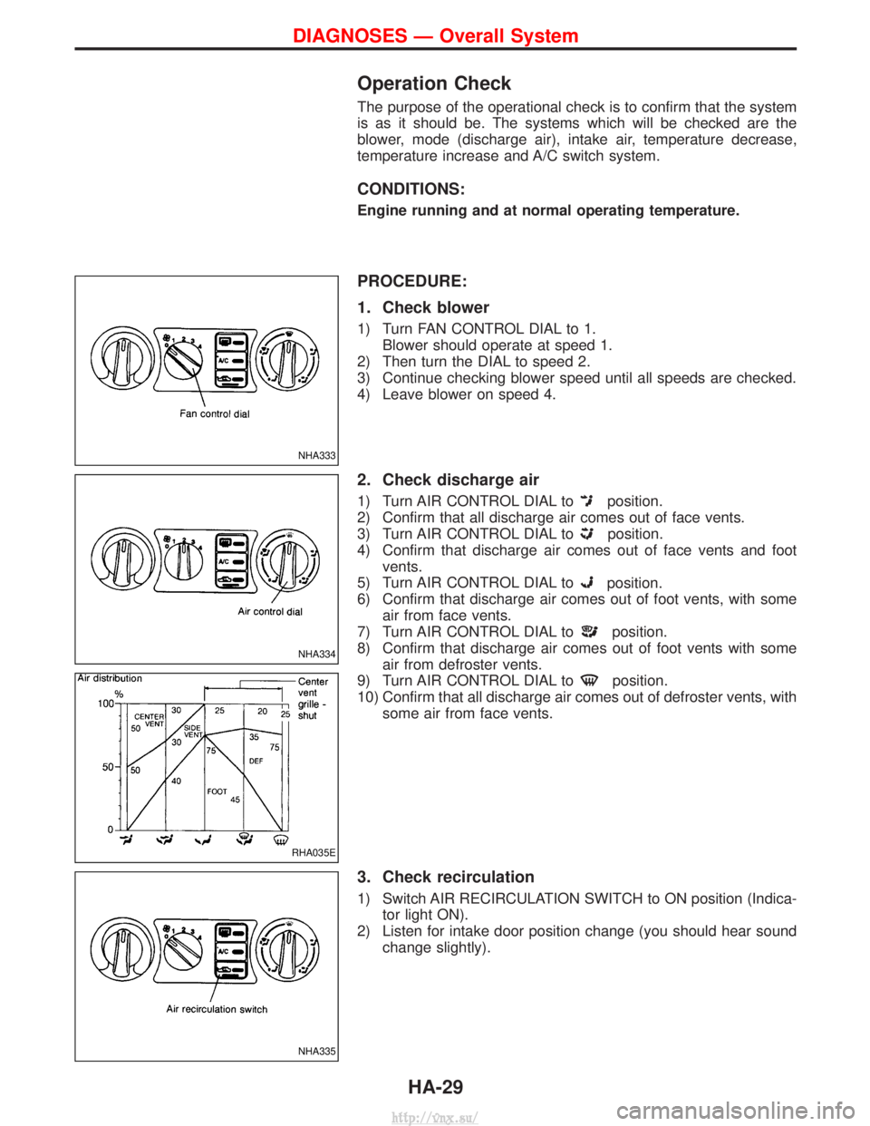
1) Turn FAN CONTROL DIAL to 1.Blower should operate at speed 1.
2) Then turn the DIAL to speed 2.
3) Continue checking blower speed until all speeds are checked.
4) Leave blower on speed 4.
2. Check discharge air
1) Turn AIR CONTROL DIAL toposition.
2) Confirm that all discharge air comes out of face vents.
3) Turn AIR CONTROL DIAL to
position.
4) Confirm that discharge air comes out of face vents and foot vents.
5) Turn AIR CONTROL DIAL to
position.
6) Confirm that discharge air comes out of foot vents, with some air from face vents.
7) Turn AIR CONTROL DIAL to
position.
8) Confirm that discharge air comes out of foot vents with some air from defroster vents.
9) Turn AIR CONTROL DIAL to
position.
10) Confirm that all discharge air comes out of defroster vents, with some air from face vents.
3. Check recirculation
1) Switch AIR RECIRCULATION SWITCH to ON position (Indica-tor light ON).
2) Listen for intake door position change (you should hear sound change slightly).
NHA333
NHA334
RHA035E
NHA335
DIAGNOSES Ð Overall System
HA-29
http://vnx.su/
Page 1427 of 1833
4. Check temperature decrease
1) Turn TEMPERATURE CONTROL DIAL to full cold (counter-clockwise).
2) Check for cold air at discharge air outlets.
5. Check temperature increase
1) Turn TEMPERATURE CONTROL DIAL to full hot (clockwise).
2) Check for hot air at discharge air outlets.
6. Check A/C switch
Turn FAN CONTROL DIAL to the desired position (1 to 4) and
switch AIR CONDITIONER SWITCH to turn ON air conditioner.
Indicator light will come on when air conditioner is ON.
NHA336
NHA337
NHA338
DIAGNOSES Ð Overall System
Operation Check (Cont'd)
HA-30
http://vnx.su/
Page 1428 of 1833
Performance Chart
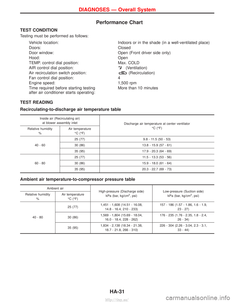
TEST CONDITION
Testing must be performed as follows:
Vehicle location:Indoors or in the shade (in a well-ventilated place)
Doors: Closed
Door window: Open (Front driver side only)
Hood: Open
TEMP. control dial position: Max. COLD
AIR control dial position:
(Ventilation)
Air recirculation switch position:
(Recirculation)
Fan control dial position: 4
Engine speed: 1,500 rpm
Time required before starting testing
after air conditioner starts operating: More than 10 minutes
TEST READING
Recirculating-to-discharge air temperature table
Inside air (Recirculating air)
at blower assembly inlet Discharge air temperature at center ventilator
ÉC (ÉF)
Relative humidity
% Air temperature
ÉC (ÉF)
40-60 25 (77) 9.8 - 11.5 (50 - 53)
30 (86) 13.8 - 15.9 (57 - 61)
35 (95) 17.9 - 20.3 (64 - 69)
60-80 25 (77) 11.5 - 13.3 (53 - 56)
30 (86) 15.9 - 18.0 (61 - 64)
35 (95) 20.3 - 22.7 (69 - 73)
Ambient air temperature-to-compressor pressure table
Ambient air
High-pressure (Discharge side)
kPa (bar, kg/cm
2, psi) Low-pressure (Suction side)
kPa (bar, kg/cm2, psi)
Relative humidity
% Air temperature
ÉC (ÉF)
40-80 25 (77)
1,451 - 1,608 (14.51 - 16.08,
14.8 - 16.4, 210 - 233) 157 - 186 (1.57 - 1.86, 1.6 - 1.9,
23 - 27)
30 (86) 1,569 - 1,804 (15.69 - 18.04,
16.0 - 18.4, 228 - 262) 176 - 235 (1.76 - 2.35, 1.8 - 2.4,
26 - 34)
35 (95) 1,834 - 2,138 (18.34 - 21.38,
18.7 - 21.8, 266 - 310) 226 - 304 (2.26 - 3.04, 2.3 - 3.1,
33 - 44)
DIAGNOSES Ð Overall System
HA-31
http://vnx.su/
Page 1432 of 1833
Gauge indicationRefrigerant cycleProbable causeCorrective action
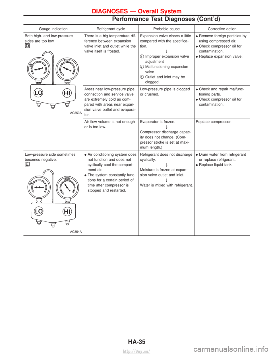
Both high- and low-pressure
sides are too low.
AC353A
There is a big temperature dif-
ference between expansion
valve inlet and outlet while the
valve itself is frosted. Expansion valve closes a little
compared with the specifica-
tion.
"
q
1Improper expansion valve
adjustment
q
2Malfunctioning expansion
valve
q
3Outlet and inlet may be
clogged. I
Remove foreign particles by
using compressed air.
I Check compressor oil for
contamination.
I Replace expansion valve.
Areas near low-pressure pipe
connection and service valve
are extremely cold as com-
pared with areas near expan-
sion valve outlet and evapora-
tor. Low-pressure pipe is clogged
or crushed.
I
Check and repair malfunc-
tioning parts.
I Check compressor oil for
contamination.
Air flow volume is not enough
or is too low. Evaporator is frozen.
"
Compressor discharge capac-
ity does not change. (Com-
pressor stroke is set at maxi-
mum length.) Replace compressor.
Low-pressure side sometimes
becomes negative.
AC354A
I Air conditioning system does
not function and does not
cyclically cool the compart-
ment air.
I The system constantly func-
tions for a certain period of
time after compressor is
stopped and restarted. Refrigerant does not discharge
cyclically.
"
Moisture is frozen at expan-
sion valve outlet and inlet. "
Water is mixed with refrigerant. I
Drain water from refrigerant
or replace refrigerant.
I Replace liquid tank.
DIAGNOSES Ð Overall System
Performance Test Diagnoses (Cont'd)
HA-35
http://vnx.su/
Page 1435 of 1833
Preliminary Check
PRELIMINARY CHECK 1
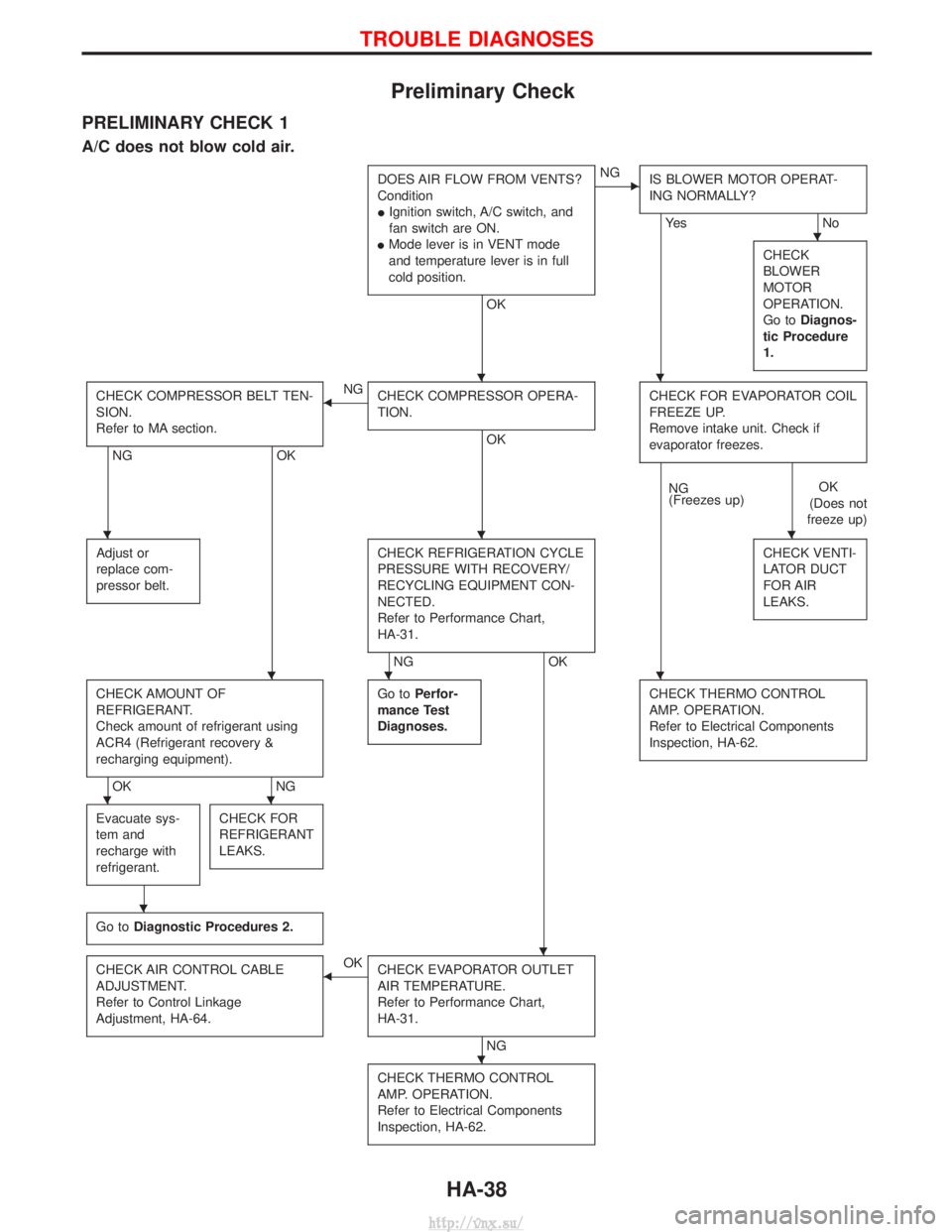
A/C does not blow cold air.
DOES AIR FLOW FROM VENTS?
Condition
IIgnition switch, A/C switch, and
fan switch are ON.
I Mode lever is in VENT mode
and temperature lever is in full
cold position.
OK
ENG
IS BLOWER MOTOR OPERAT-
ING NORMALLY?
Ye s N o
CHECK
BLOWER
MOTOR
OPERATION.
Go to Diagnos-
tic Procedure
1.
CHECK COMPRESSOR BELT TEN-
SION.
Refer to MA section.
NG OK
FNG
CHECK COMPRESSOR OPERA-
TION.
OK CHECK FOR EVAPORATOR COIL
FREEZE UP.
Remove intake unit. Check if
evaporator freezes.
NG
(Freezes up)
OK
(Does not
freeze up)
Adjust or
replace com-
pressor belt.
CHECK REFRIGERATION CYCLE
PRESSURE WITH RECOVERY/
RECYCLING EQUIPMENT CON-
NECTED.
Refer to Performance Chart,
HA-31.
NG OK CHECK VENTI-
LATOR DUCT
FOR AIR
LEAKS.
CHECK AMOUNT OF
REFRIGERANT.
Check amount of refrigerant using
ACR4 (Refrigerant recovery &
recharging equipment).
OK
NGGo to
Perfor-
mance Test
Diagnoses.
CHECK THERMO CONTROL
AMP. OPERATION.
Refer to Electrical Components
Inspection, HA-62.
Evacuate sys-
tem and
recharge with
refrigerant.CHECK FOR
REFRIGERANT
LEAKS.
Go to Diagnostic Procedures 2.
CHECK AIR CONTROL CABLE
ADJUSTMENT.
Refer to Control Linkage
Adjustment, HA-64.FOK
CHECK EVAPORATOR OUTLET
AIR TEMPERATURE.
Refer to Performance Chart,
HA-31.
NG
CHECK THERMO CONTROL
AMP. OPERATION.
Refer to Electrical Components
Inspection, HA-62.
H
HH
HHH
HHH
HH
H
H
H
TROUBLE DIAGNOSES
HA-38
http://vnx.su/
Page 1449 of 1833
Main Power Supply and Ground Circuit Check
POWER SUPPLY CIRCUIT CHECK FOR A/C SYSTEM
Check power supply circuit for air conditioning system.
Refer to ªPOWER SUPPLY ROUTINGº in EL section and ªWir-
ing Diagramº.
TROUBLE DIAGNOSES
HA-52
http://vnx.su/
Page 1459 of 1833
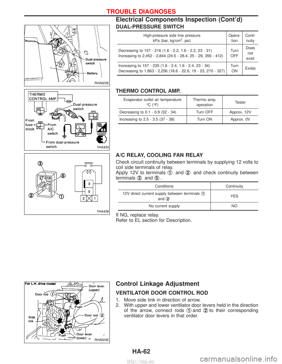
DUAL-PRESSURE SWITCH
High-pressure side line pressurekPa (bar, kg/cm2, psi) Opera-
tion Conti-
nuity
Decreasing to 157 - 216 (1.6 - 2.2, 1.6 - 2.2, 23 - 31)
Increasing to 2,452 - 2,844 (24.5 - 28.4, 25 - 29, 356 - 412) Turn
OFF Does
not
exist
Increasing to 157 - 235 (1.6 - 2.4, 1.6 - 2.4, 23 - 34)
Decreasing to 1,863 - 2,256 (18.6 - 22.6, 19 - 23, 270 - 327) Turn
ON Exists
THERMO CONTROL AMP.
Evaporator outlet air temperature
ÉC (ÉF) Thermo amp.
operation Tester
Decreasing to 0.1 - 0.9 (32 - 34) Turn OFF Approx. 12V
Increasing to 2.5 - 3.5 (37 - 38) Turn ON Approx. 0V
A/C RELAY, COOLING FAN RELAY
Check circuit continuity between terminals by supplying 12 volts to
coil side terminals of relay.
Apply 12V to terminals q
1andq2and check continuity between
terminals q
3andq5.
Conditions
Continuity
12V direct current supply between terminals q
1
andq2YES
No current supply NO
If NG, replace relay.
Refer to EL section for Description.
Control Linkage Adjustment
VENTILATOR DOOR CONTROL ROD
1. Move side link in direction of arrow.
2. With upper and lower ventilator door levers held in the direction of the arrow, connect rods q
1andq2to their corresponding
ventilator door levers in that order.
RHA023E
YHA435
YHA436
RHA024E
TROUBLE DIAGNOSES
Electrical Components Inspection (Cont'd)
HA-62
http://vnx.su/
Page 1496 of 1833
WIRING DIAGRAM REFERENCE CHART
ENGINE CONTROL SYSTEM, IGNITION SYSTEM ........................................................................\
........................EC SECTION
RESTRAINT SYSTEM (AIR BAG) ........................................................................\
...................................................RS SECTION
HEATER AND AIR CONDITIONER ........................................................................\
..................................................HA SECTION
CONTENTS(Cont'd)
EL-3
http://vnx.su/