2004 NISSAN TERRANO air condition
[x] Cancel search: air conditionPage 884 of 1833
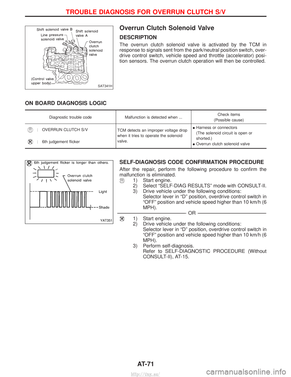
Overrun Clutch Solenoid Valve
DESCRIPTION
The overrun clutch solenoid valve is activated by the TCM in
response to signals sent from the park/neutral position switch, over-
drive control switch, vehicle speed and throttle (accelerator) posi-
tion sensors. The overrun clutch operation will then be controlled.
ON BOARD DIAGNOSIS LOGIC
Diagnostic trouble codeMalfunction is detected when ... Check items
(Possible cause)
: OVERRUN CLUTCH S/V TCM detects an improper voltage drop
when it tries to operate the solenoid
valve.I
Harness or connectors
(The solenoid circuit is open or
shorted.)
I Overrun clutch solenoid valve
: 6th judgement flicker
SELF-DIAGNOSIS CODE CONFIRMATION PROCEDURE
After the repair, perform the following procedure to confirm the
malfunction is eliminated.
1) Start engine.
2) Select ªSELF-DIAG RESULTSº mode with CONSULT-II.
3) Drive vehicle under the following conditions:
Selector lever in ªDº position, overdrive control switch in
ªOFFº position and vehicle speed higher than 10 km/h (6
MPH).
----------------------------------------------------------------------------------------------------------------------------------------------------------------------------------------------------------------------------------------------------------- -OR------------------------------------------------------------------------------------------------------------------------------------------------------------------------------------------------------------------------------------------------------------
1) Start engine.
2) Drive vehicle under the following conditions:
Selector lever in ªDº position, overdrive control switch in
ªOFFº position and vehicle speed higher than 10 km/h (6
MPH).
3) Perform self-diagnosis. Refer to SELF-DIAGNOSTIC PROCEDURE (Without
CONSULT-II), AT-15.
SAT341H
YAT351
TROUBLE DIAGNOSIS FOR OVERRUN CLUTCH S/V
AT-71
http://vnx.su/
Page 887 of 1833
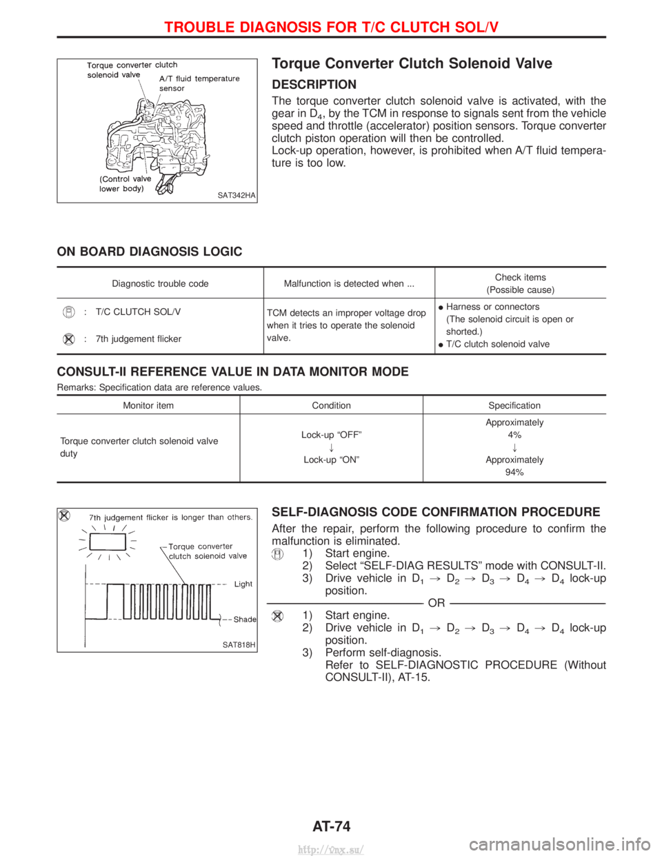
Torque Converter Clutch Solenoid Valve
DESCRIPTION
The torque converter clutch solenoid valve is activated, with the
gear in D
4, by the TCM in response to signals sent from the vehicle
speed and throttle (accelerator) position sensors. Torque converter
clutch piston operation will then be controlled.
Lock-up operation, however, is prohibited when A/T fluid tempera-
ture is too low.
ON BOARD DIAGNOSIS LOGIC
Diagnostic trouble code Malfunction is detected when ... Check items
(Possible cause)
: T/C CLUTCH SOL/V TCM detects an improper voltage drop
when it tries to operate the solenoid
valve.I
Harness or connectors
(The solenoid circuit is open or
shorted.)
I T/C clutch solenoid valve
: 7th judgement flicker
CONSULT-II REFERENCE VALUE IN DATA MONITOR MODE
Remarks: Specification data are reference values.
Monitor item ConditionSpecification
Torque converter clutch solenoid valve
duty Lock-up ªOFFº
"
Lock-up ªONº Approximately
4%"
Approximately 94%
SELF-DIAGNOSIS CODE CONFIRMATION PROCEDURE
After the repair, perform the following procedure to confirm the
malfunction is eliminated.
1) Start engine.
2) Select ªSELF-DIAG RESULTSº mode with CONSULT-II.
3) Drive vehicle in D
1,D2,D3,D4,D4lock-up
position.
----------------------------------------------------------------------------------------------------------------------------------------------------------------------------------------------------------------------------------------------------------- -OR------------------------------------------------------------------------------------------------------------------------------------------------------------------------------------------------------------------------------------------------------------
1) Start engine.
2) Drive vehicle in D
1,D2,D3,D4,D4lock-up
position.
3) Perform self-diagnosis. Refer to SELF-DIAGNOSTIC PROCEDURE (Without
CONSULT-II), AT-15.
SAT342HA
SAT818H
TROUBLE DIAGNOSIS FOR T/C CLUTCH SOL/V
AT-74
http://vnx.su/
Page 891 of 1833
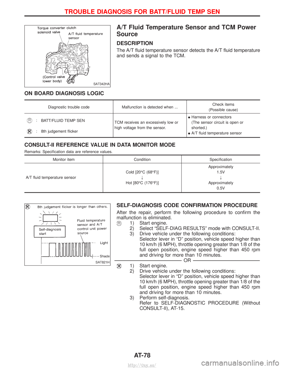
A/T Fluid Temperature Sensor and TCM Power
Source
DESCRIPTION
The A/T fluid temperature sensor detects the A/T fluid temperature
and sends a signal to the TCM.
ON BOARD DIAGNOSIS LOGIC
Diagnostic trouble codeMalfunction is detected when ... Check items
(Possible cause)
: BATT/FLUID TEMP SEN
TCM receives an excessively low or
high voltage from the sensor.I
Harness or connectors
(The sensor circuit is open or
shorted.)
I A/T fluid temperature sensor
: 8th judgement flicker
CONSULT-II REFERENCE VALUE IN DATA MONITOR MODE
Remarks: Specification data are reference values.
Monitor item ConditionSpecification
A/T fluid temperature sensor Cold [20ÉC (68ÉF)]
"
Hot [80ÉC (176ÉF)] Approximately
1.5V"
Approximately 0.5V
SELF-DIAGNOSIS CODE CONFIRMATION PROCEDURE
After the repair, perform the following procedure to confirm the
malfunction is eliminated.
1) Start engine.
2) Select ªSELF-DIAG RESULTSº mode with CONSULT-II.
3) Drive vehicle under the following conditions:Selector lever in ªDº position, vehicle speed higher than
10 km/h (6 MPH), throttle opening greater than 1/8 of the
full open position, engine speed higher than 450 rpm
and driving for more than 10 minutes.
----------------------------------------------------------------------------------------------------------------------------------------------------------------------------------------------------------------------------------------------------------- -OR------------------------------------------------------------------------------------------------------------------------------------------------------------------------------------------------------------------------------------------------------------
1) Start engine.
2) Drive vehicle under the following conditions:
Selector lever in ªDº position, vehicle speed higher than
10 km/h (6 MPH), throttle opening greater than 1/8 of the
full open position, engine speed higher than 450 rpm
and driving for more than 10 minutes.
3) Perform self-diagnosis. Refer to SELF-DIAGNOSTIC PROCEDURE (Without
CONSULT-II), AT-15.
SAT342HA
SAT821H
TROUBLE DIAGNOSIS FOR BATT/FLUID TEMP SEN
AT-78
http://vnx.su/
Page 895 of 1833
Engine Speed Signal
DESCRIPTION
The engine speed signal is sent from the ECM to the TCM.
ON BOARD DIAGNOSIS LOGIC
Diagnostic trouble codeMalfunction is detected when ... Check items
(Possible cause)
: ENGINE SPEED SIG
TCM does not receive the proper volt-
age signal from ECM.I
Harness or connectors
(The sensor circuit is open or
shorted.)
:
9th judgement flicker
SELF-DIAGNOSIS CODE CONFIRMATION PROCEDURE
After the repair, perform the following procedure to confirm the
malfunction is eliminated.
1) Start engine.
2) Select ªSELF-DIAG RESULTSº mode with CONSULT-II.
3) Drive vehicle under the following conditions:
Selector lever in ªDº position, vehicle speed higher than
10 km/h (6 MPH), throttle opening greater than 1/8 of the
full throttle position and driving for more than 10 sec-
onds.
----------------------------------------------------------------------------------------------------------------------------------------------------------------------------------------------------------------------------------------------------------- -OR------------------------------------------------------------------------------------------------------------------------------------------------------------------------------------------------------------------------------------------------------------
1) Start engine.
2) Drive vehicle under the following conditions:
Selector lever in ªDº position, vehicle speed higher than
10 km/h (6 MPH), throttle opening greater than 1/8 of the
full throttle position and driving for more than 10 sec-
onds.
3) Perform self-diagnosis. Refer to SELF-DIAGNOSTIC PROCEDURE (Without
CONSULT-II), AT-15.SAT823H
TROUBLE DIAGNOSIS FOR ENGINE SPEED SIG
AT-82
http://vnx.su/
Page 899 of 1833
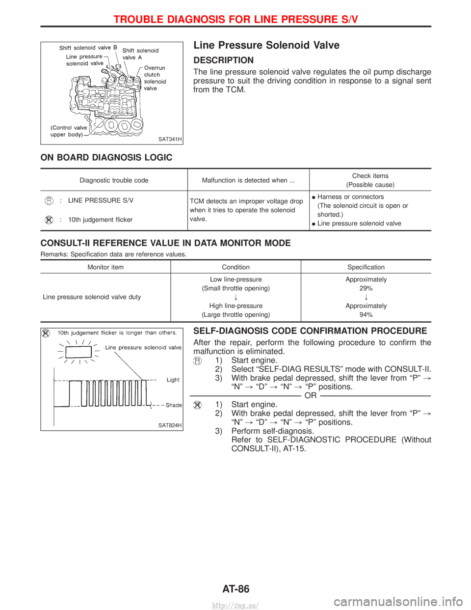
Line Pressure Solenoid Valve
DESCRIPTION
The line pressure solenoid valve regulates the oil pump discharge
pressure to suit the driving condition in response to a signal sent
from the TCM.
ON BOARD DIAGNOSIS LOGIC
Diagnostic trouble codeMalfunction is detected when ... Check items
(Possible cause)
: LINE PRESSURE S/V TCM detects an improper voltage drop
when it tries to operate the solenoid
valve.I
Harness or connectors
(The solenoid circuit is open or
shorted.)
I Line pressure solenoid valve
: 10th judgement flicker
CONSULT-II REFERENCE VALUE IN DATA MONITOR MODE
Remarks: Specification data are reference values.
Monitor item ConditionSpecification
Line pressure solenoid valve duty Low line-pressure
(Small throttle opening) "
High line-pressure
(Large throttle opening) Approximately
29%"
Approximately 94%
SELF-DIAGNOSIS CODE CONFIRMATION PROCEDURE
After the repair, perform the following procedure to confirm the
malfunction is eliminated.
1) Start engine.
2) Select ªSELF-DIAG RESULTSº mode with CONSULT-II.
3) With brake pedal depressed, shift the lever from ªPº ,
ªNº ,ªDº ,ªNº ,ªPº positions.
----------------------------------------------------------------------------------------------------------------------------------------------------------------------------------------------------------------------------------------------------------- -OR------------------------------------------------------------------------------------------------------------------------------------------------------------------------------------------------------------------------------------------------------------
1) Start engine.
2) With brake pedal depressed, shift the lever from ªPº ,
ªNº ,ªDº ,ªNº ,ªPº positions.
3) Perform self-diagnosis. Refer to SELF-DIAGNOSTIC PROCEDURE (Without
CONSULT-II), AT-15.
SAT341H
SAT824H
TROUBLE DIAGNOSIS FOR LINE PRESSURE S/V
AT-86
http://vnx.su/
Page 920 of 1833
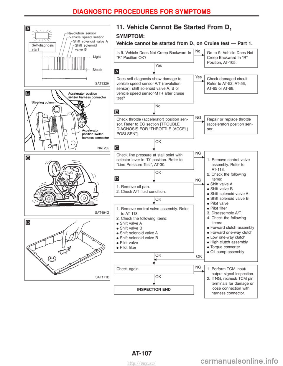
11. Vehicle Cannot Be Started From D1
SYMPTOM:
Vehicle cannot be started from D1on Cruise test Ð Part 1.
Is 9. Vehicle Does Not Creep Backward In
ªRº Position OK?
Ye s
ENoGo to 9. Vehicle Does Not
Creep Backward In ªRº
Position, AT-105.
Does self-diagnosis show damage to
vehicle speed sensor×A/T (revolution
sensor), shift solenoid valve A, B or
vehicle speed sensor×MTR after cruise
test?
No
EYe sCheck damaged circuit.
Refer to AT-52, AT-56,
AT-65 or AT-68.
Check throttle (accelerator) position sen-
sor. Refer to EC section [TROUBLE
DIAGNOSIS FOR ªTHROTTLE (ACCEL)
POSI SENº].
OK
ENGRepair or replace throttle
(accelerator) position sen-
sor.
Check line pressure at stall point with
selector lever in ªDº position. Refer to
ªLine Pressure Testº, AT-30.
OK
ENG
1. Remove control valveassembly. Refer to
AT-118.
2. Check the following items:
I Shift valve A
I Shift valve B
I Shift solenoid valve A
I Shift solenoid valve B
I Pilot valve
I Pilot filter
3. Disassemble A/T.
4. Check the following items:
I Forward clutch assembly
I Forward one-way clutch
I Low one-way clutch
I High clutch assembly
I Torque converter
I Oil pump assembly
1. Remove oil pan.
2. Check A/T fluid condition.
OK
ENG
1. Remove control valve assembly. Refer to AT-118.
2. Check the following items:
I Shift valve A
I Shift valve B
I Shift solenoid valve A
I Shift solenoid valve B
I Pilot valve
I Pilot filter
OKFOK
Check again.
OK
ENG 1. Perform TCM input/
output signal inspection.
2. If NG, recheck TCM pin terminals for damage or
loose connection with
harness connector.
INSPECTION END
SAT832H
NAT262
SAT494G
SAT171B
H
H
H
H
H
HH
H
DIAGNOSTIC PROCEDURES FOR SYMPTOMS
AT-107
http://vnx.su/
Page 921 of 1833
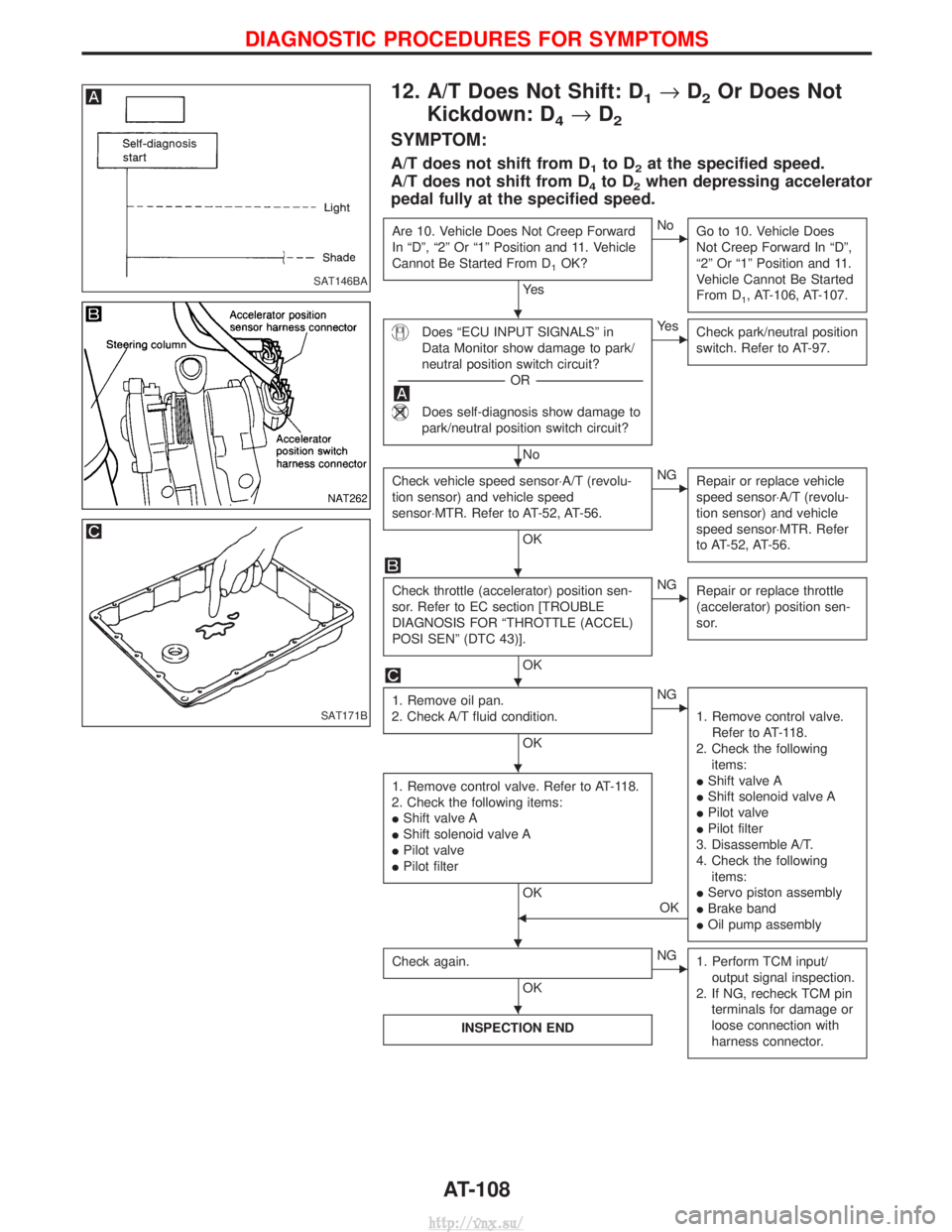
12. A/T Does Not Shift: D1®D2Or Does Not
Kickdown: D
4® D2
SYMPTOM:
A/T does not shift from D1to D2at the specified speed.
A/T does not shift from D
4to D2when depressing accelerator
pedal fully at the specified speed.
Are 10. Vehicle Does Not Creep Forward
In ªDº, ª2º Or ª1º Position and 11. Vehicle
Cannot Be Started From D
1OK?
Ye s
ENo Go to 10. Vehicle Does
Not Creep Forward In ªDº,
ª2º Or ª1º Position and 11.
Vehicle Cannot Be Started
From D
1, AT-106, AT-107.
Does ªECU INPUT SIGNALSº in
Data Monitor show damage to park/
neutral position switch circuit?
---------------------------------------------------------------------------------------------------------------------- -OR -----------------------------------------------------------------------------------------------------------------------
Does self-diagnosis show damage to
park/neutral position switch circuit?
No
EYe s
Check park/neutral position
switch. Refer to AT-97.
Check vehicle speed sensor×A/T (revolu-
tion sensor) and vehicle speed
sensor×MTR. Refer to AT-52, AT-56.
OK
ENGRepair or replace vehicle
speed sensor×A/T (revolu-
tion sensor) and vehicle
speed sensor×MTR. Refer
to AT-52, AT-56.
Check throttle (accelerator) position sen-
sor. Refer to EC section [TROUBLE
DIAGNOSIS FOR ªTHROTTLE (ACCEL)
POSI SENº (DTC 43)].
OK
ENGRepair or replace throttle
(accelerator) position sen-
sor.
1. Remove oil pan.
2. Check A/T fluid condition.
OK
ENG
1. Remove control valve.Refer to AT-118.
2. Check the following items:
I Shift valve A
I Shift solenoid valve A
I Pilot valve
I Pilot filter
3. Disassemble A/T.
4. Check the following items:
I Servo piston assembly
I Brake band
I Oil pump assembly
1. Remove control valve. Refer to AT-118.
2. Check the following items:
I Shift valve A
I Shift solenoid valve A
I Pilot valve
I Pilot filter
OK
FOK
Check again.
OK
ENG 1. Perform TCM input/
output signal inspection.
2. If NG, recheck TCM pin terminals for damage or
loose connection with
harness connector.
INSPECTION END
SAT146BA
NAT262
SAT171B
H
H
H
H
H
HH
H
DIAGNOSTIC PROCEDURES FOR SYMPTOMS
AT-108
http://vnx.su/
Page 922 of 1833
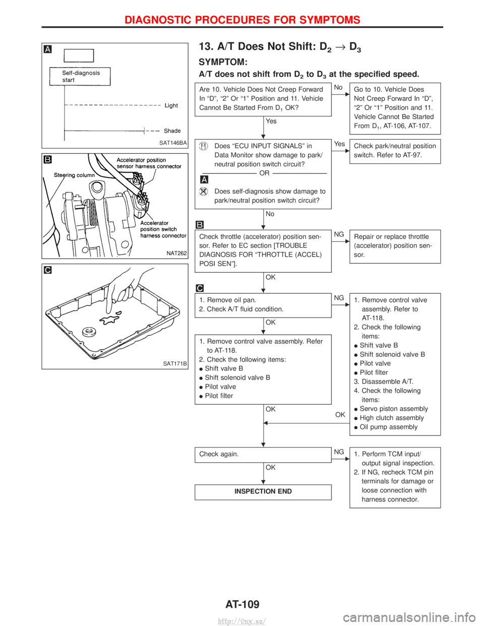
13. A/T Does Not Shift: D2®D3
SYMPTOM:
A/T does not shift from D2to D3at the specified speed.
Are 10. Vehicle Does Not Creep Forward
In ªDº, ª2º Or ª1º Position and 11. Vehicle
Cannot Be Started From D
1OK?
Ye s
ENo
Go to 10. Vehicle Does
Not Creep Forward In ªDº,
ª2º Or ª1º Position and 11.
Vehicle Cannot Be Started
From D
1, AT-106, AT-107.
Does ªECU INPUT SIGNALSº in
Data Monitor show damage to park/
neutral position switch circuit?
---------------------------------------------------------------------------------------------------------------------- -OR -----------------------------------------------------------------------------------------------------------------------
Does self-diagnosis show damage to
park/neutral position switch circuit?
No
EYe s
Check park/neutral position
switch. Refer to AT-97.
Check throttle (accelerator) position sen-
sor. Refer to EC section [TROUBLE
DIAGNOSIS FOR ªTHROTTLE (ACCEL)
POSI SENº].
OK
ENGRepair or replace throttle
(accelerator) position sen-
sor.
1. Remove oil pan.
2. Check A/T fluid condition.
OK
ENG 1. Remove control valve
assembly. Refer to
AT-118.
2. Check the following items:
I Shift valve B
I Shift solenoid valve B
I Pilot valve
I Pilot filter
3. Disassemble A/T.
4. Check the following items:
I Servo piston assembly
I High clutch assembly
I Oil pump assembly
1. Remove control valve assembly. Refer
to AT-118.
2. Check the following items:
I Shift valve B
I Shift solenoid valve B
I Pilot valve
I Pilot filter
OK
OK
F
Check again.
OK
ENG1. Perform TCM input/
output signal inspection.
2. If NG, recheck TCM pin terminals for damage or
loose connection with
harness connector.
INSPECTION END
SAT146BA
NAT262
SAT171B
H
H
H
H
HH
H
DIAGNOSTIC PROCEDURES FOR SYMPTOMS
AT-109
http://vnx.su/