Page 716 of 1833
Description
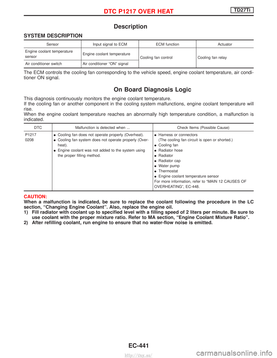
SYSTEM DESCRIPTION
SensorInput signal to ECM ECM functionActuator
Engine coolant temperature
sensor Engine coolant temperature
Cooling fan control Cooling fan relay
Air conditioner switch Air conditioner ªONº signal
The ECM controls the cooling fan corresponding to the vehicle speed, engine coolant temperature, air condi-
tioner ON signal.
On Board Diagnosis Logic
This diagnosis continuously monitors the engine coolant temperature.
If the cooling fan or another component in the cooling system malfunctions, engine coolant temperature will
rise.
When the engine coolant temperature reaches an abnormally high temperature condition, a malfunction is
indicated.
DTC Malfunction is detected when ... Check Items (Possible Cause)
P1217
0208 I
Cooling fan does not operate properly (Overheat).
I Cooling fan system does not operate properly (Over-
heat).
I Engine coolant was not added to the system using
the proper filling method. I
Harness or connectors
(The cooling fan circuit is open or shorted.)
I Cooling fan
I Radiator hose
I Radiator
I Radiator cap
I Water pump
I Thermostat
I Engine coolant temperature sensor
For more information, refer to ªMAIN 12 CAUSES OF
OVERHEATINGº, EC-448.
CAUTION:
When a malfunction is indicated, be sure to replace the coolant following the procedure in the LC
section, ªChanging Engine Coolantº. Also, replace the engine oil.
1) Fill radiator with coolant up to specified level with a filling speed of 2 liters per minute. Be sure to use coolant with the proper mixture ratio. Refer to MA section, ªEngine Coolant Mixture Ratioº.
2) After refilling coolant, run engine to ensure that no water-flow noise is emitted.
DTC P1217 OVER HEATTD27Ti
EC-441
http://vnx.su/
Page 717 of 1833
Overall Function Check
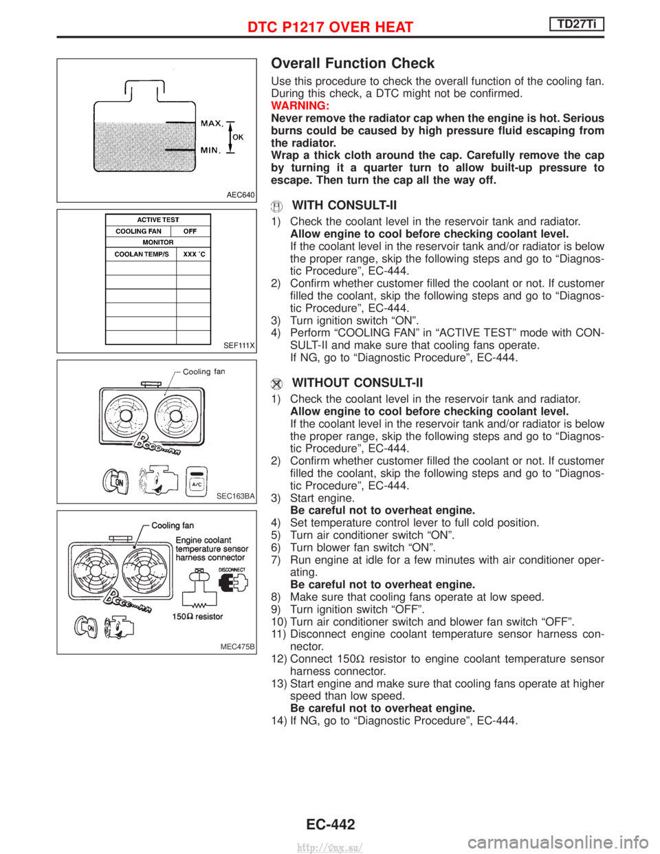
Use this procedure to check the overall function of the cooling fan.
During this check, a DTC might not be confirmed.
WARNING:
Never remove the radiator cap when the engine is hot. Serious
burns could be caused by high pressure fluid escaping from
the radiator.
Wrap a thick cloth around the cap. Carefully remove the cap
by turning it a quarter turn to allow built-up pressure to
escape. Then turn the cap all the way off.
WITH CONSULT-II
1) Check the coolant level in the reservoir tank and radiator.Allow engine to cool before checking coolant level.
If the coolant level in the reservoir tank and/or radiator is below
the proper range, skip the following steps and go to ªDiagnos-
tic Procedureº, EC-444.
2) Confirm whether customer filled the coolant or not. If customer filled the coolant, skip the following steps and go to ªDiagnos-
tic Procedureº, EC-444.
3) Turn ignition switch ªONº.
4) Perform ªCOOLING FANº in ªACTIVE TESTº mode with CON- SULT-II and make sure that cooling fans operate.
If NG, go to ªDiagnostic Procedureº, EC-444.
WITHOUT CONSULT-II
1) Check the coolant level in the reservoir tank and radiator.Allow engine to cool before checking coolant level.
If the coolant level in the reservoir tank and/or radiator is below
the proper range, skip the following steps and go to ªDiagnos-
tic Procedureº, EC-444.
2) Confirm whether customer filled the coolant or not. If customer filled the coolant, skip the following steps and go to ªDiagnos-
tic Procedureº, EC-444.
3) Start engine. Be careful not to overheat engine.
4) Set temperature control lever to full cold position.
5) Turn air conditioner switch ªONº.
6) Turn blower fan switch ªONº.
7) Run engine at idle for a few minutes with air conditioner oper- ating.
Be careful not to overheat engine.
8) Make sure that cooling fans operate at low speed.
9) Turn ignition switch ªOFFº.
10) Turn air conditioner switch and blower fan switch ªOFFº.
11) Disconnect engine coolant temperature sensor harness con- nector.
12) Connect 150W resistor to engine coolant temperature sensor
harness connector.
13) Start engine and make sure that cooling fans operate at higher speed than low speed.
Be careful not to overheat engine.
14) If NG, go to ªDiagnostic Procedureº, EC-444.
AEC640
SEF111X
SEC163BA
MEC475B
DTC P1217 OVER HEATTD27Ti
EC-442
http://vnx.su/
Page 719 of 1833
Diagnostic Procedure
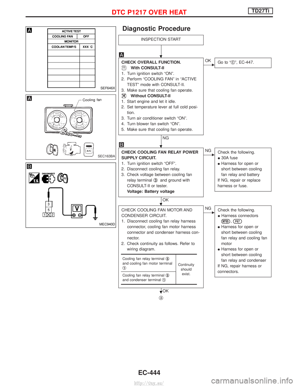
INSPECTION START
CHECK OVERALL FUNCTION.
With CONSULT-II
1. Turn ignition switch ªONº.
2. Perform ªCOOLING FANº in ªACTIVE TESTº mode with CONSULT-II.
3. Make sure that cooling fan operate.
Without CONSULT-II
1. Start engine and let it idle.
2. Set temperature lever at full cold posi- tion.
3. Turn air conditioner switch ªONº.
4. Turn blower fan switch ªONº.
5. Make sure that cooling fan operate.
NG
EOK Go to ª qCº, EC-447.
CHECK COOLING FAN RELAY POWER
SUPPLY CIRCUIT.
1. Turn ignition switch ªOFFº.
2. Disconnect cooling fan relay.
3. Check voltage between cooling fan relay terminal q
3and ground with
CONSULT-II or tester.
Voltage: Battery voltage
OK
ENG Check the following.
I30A fuse
I Harness for open or
short between cooling
fan relay and battery
If NG, repair or replace
harness or fuse.
CHECK COOLING FAN MOTOR AND
CONDENSER CIRCUIT.
1. Disconnect cooling fan relay harness connector, cooling fan motor harness
connector and condenser harness con-
nector.
2. Check continuity as follows. Refer to wiring diagram.
OK
ENG Check the following.
IHarness connectors
M785,F67
IHarness for open or
short between cooling
fan relay and cooling fan
motor
I Harness for open or
short between cooling
fan relay and condenser
If NG, repair harness or
connectors.
qA
Cooling fan relay terminal q5and cooling fan motor terminal
q1Continuity
shouldexist.
Cooling fan relay terminal q
5and condenser terminalq1
SEF646X
SEC163BA
MEC940D
H
H
H
H
DTC P1217 OVER HEATTD27Ti
EC-444
http://vnx.su/
Page 729 of 1833
System Description
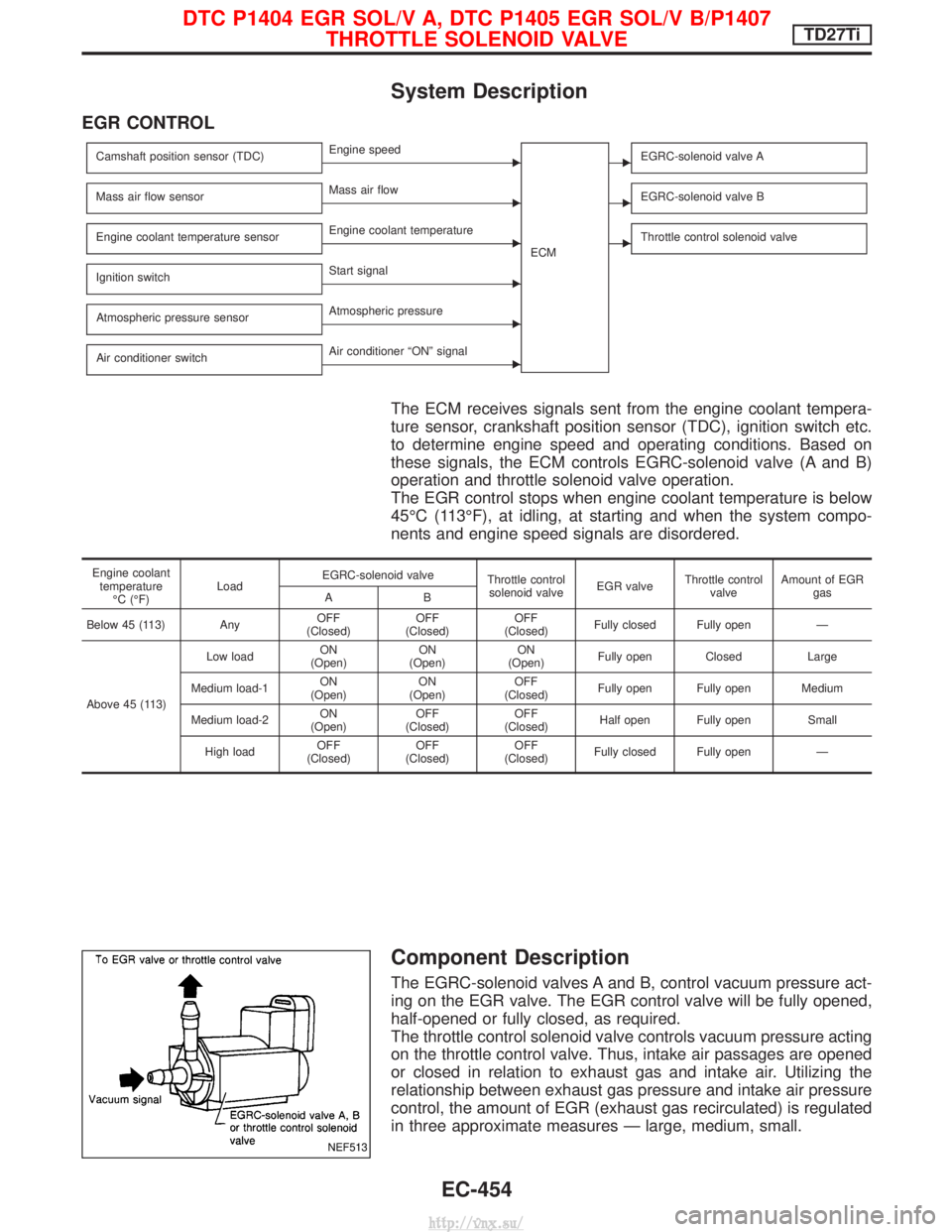
EGR CONTROL
Camshaft position sensor (TDC)EEngine speedECMEEGRC-solenoid valve A
Mass air flow sensorEMass air flowEEGRC-solenoid valve B
Engine coolant temperature sensorEEngine coolant temperatureEThrottle control solenoid valve
Ignition switchEStart signal
Atmospheric pressure sensor
EAtmospheric pressure
Air conditioner switch
EAir conditioner ªONº signal
The ECM receives signals sent from the engine coolant tempera-
ture sensor, crankshaft position sensor (TDC), ignition switch etc.
to determine engine speed and operating conditions. Based on
these signals, the ECM controls EGRC-solenoid valve (A and B)
operation and throttle solenoid valve operation.
The EGR control stops when engine coolant temperature is below
45ÉC (113ÉF), at idling, at starting and when the system compo-
nents and engine speed signals are disordered.
Engine coolant temperature ÉC (ÉF) Load
EGRC-solenoid valve
Throttle control
solenoid valve EGR valveThrottle control
valve Amount of EGR
gas
AB
Below 45 (113) Any OFF
(Closed) OFF
(Closed) OFF
(Closed) Fully closed Fully open Ð
Above 45 (113) Low load
ON
(Open) ON
(Open) ON
(Open) Fully open Closed Large
Medium load-1 ON
(Open) ON
(Open) OFF
(Closed) Fully open Fully open Medium
Medium load-2 ON
(Open) OFF
(Closed) OFF
(Closed) Half open Fully open Small
High load OFF
(Closed) OFF
(Closed) OFF
(Closed) Fully closed Fully open Ð
Component Description
The EGRC-solenoid valves A and B, control vacuum pressure act-
ing on the EGR valve. The EGR control valve will be fully opened,
half-opened or fully closed, as required.
The throttle control solenoid valve controls vacuum pressure acting
on the throttle control valve. Thus, intake air passages are opened
or closed in relation to exhaust gas and intake air. Utilizing the
relationship between exhaust gas pressure and intake air pressure
control, the amount of EGR (exhaust gas recirculated) is regulated
in three approximate measures Ð large, medium, small.
NEF513
DTC P1404 EGR SOL/V A, DTC P1405 EGR SOL/V B/P1407
THROTTLE SOLENOID VALVETD27Ti
EC-454
http://vnx.su/
Page 735 of 1833
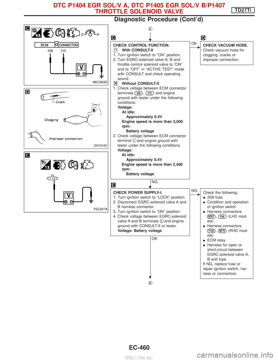
qA
CHECK CONTROL FUNCTION.
With CONSULT-II
1. Turn ignition switch to ªONº position.
2. Turn EGRC-solenoid valve A, B and throttle control solenoid valve to ªONº
and to ªOFFº in ªACTIVE TESTº mode
with CONSULT and check operating
sound.
Without CONSULT-II
1. Check voltage between ECM connector terminals
208,210and engine
ground with tester under the following
conditions.
Voltage: At idle:Approximately 0.4V
Engine speed is more than 3,000
rpm: Battery voltage
2. Check voltage between ECM connector terminal q
1and engine ground with
tester under the following conditions.
Voltage: At idle:Approximately 0.4V
Engine speed is more than 2,400
rpm: Battery voltage
NG
EOK CHECK VACUUM HOSE.
Check vacuum hose for
clogging, cracks or
improper connection.
CHECK POWER SUPPLY-I.
1. Turn ignition switch to ªLOCKº position.
2. Disconnect EGRC-solenoid valve A and B harness connector.
3. Turn ignition switch to ªONº position.
4. Check voltage between EGRC-solenoid valve A and B terminals q
2and engine
ground with CONSULT-II or tester.
Voltage: Battery voltage
OK
ENG Check the following:
I20A fuse
I Condition and operation
of ignition switch
I Harness connectors
M787,F66(LHD mod-
els)
I Harness connectors
F100,M775(RHD mod-
els)
I ECM relay
I Harness for open or
short-circuit between
EGRC-solenoid valve A,
B and fuse.
If NG, replace fuse or
repair ignition switch, har-
ness or connectors.
qB
MEC953D
SEF816F
YEC247A
H
H
H
DTC P1404 EGR SOL/V A, DTC P1405 EGR SOL/V B/P1407 THROTTLE SOLENOID VALVETD27Ti
Diagnostic Procedure (Cont'd)
EC-460
http://vnx.su/
Page 738 of 1833
Component Description
AIR CONDITIONER CUT CONTROL
Air conditioner is cut under the following conditions:
IStarting engine
I Quick acceleration from low speed
I Undershooting of idle speed
I High engine coolant temperature [above 107ÉC (225ÉF)]
I Malfunctioning of engine speed sensor, accelerator position sen-
sor or vehicle speed sensor when engine speed is below 2,100
rpm.
On Board Diagnosis Logic
DTC Malfunction is detected when .... Check Items
(Possible cause)
P1530
0805 I
Air conditioner relay signal circuit is shorted. IHarness or connectors
(The air conditioner relay signal circuit is shorted.)
I Air conditioner relay
DTC Confirmation Procedure
WITH CONSULT-II
1) Turn ignition switch and air conditioner switch to ªONº position.
2) Select ªDATA MONITORº mode with CONSULT-II.
3) Wait at least 2 seconds.
WITHOUT CONSULT-II
1) Turn ignition switch and air conditioner switch to ªONº position.
Wait at least 2 seconds.
2) Turn ignition switch to ªLOCKº position, wait at least 5 seconds and then turn to ªONº position.
3) Perform ªDiagnostic Test Mode IIº (Self-diagnostic results).
DTC P1530 AIR CONDITIONER RLYTD27Ti
EC-463
http://vnx.su/
Page 739 of 1833
Wiring Diagram
LHD MODELS
YEC154A
DTC P1530 AIR CONDITIONER RLYTD27Ti
EC-464
http://vnx.su/
Page 740 of 1833
RHD MODELS
YEC686A
DTC P1530 AIR CONDITIONER RLYTD27Ti
Wiring Diagram (Cont'd)EC-465
http://vnx.su/