Page 544 of 1833

8 CHECK HEAT UP SWITCH
Check continuity between heat up switch terminals 1 and 2 under the following conditions.
MEC984D
MTBL1321
OK or NG
OK EGO TO 12.
NG EReplace heat up switch.
9 CHECK HEAT UP SWITCH INDICATOR CIRCUIT FOR OPEN AND SHORT
1. Turn heat up switch ªOFFº.
2. Turn ignition switch ªOFFº.
3. Disconnect heat up switch harness connector.
4. Check harness continuity between heat up switch terminals 1 and 4, heat up switch terminal 3 and body ground. Refer to Wir-
ing Diagram.
Continuity should exist.
5. Also check harness for short to ground and short to power.
OK or NG
OK EGO TO 11.
NG EGO TO 10.
10 DETECT MALFUNCTIONING PART
Check the following.
IHarness connectors F108, E225
I Harness for open and short between heat up switch and heat up switch
I Harness for open and short between heat up switch and body ground
ERepair open circuit or short to ground or short to power in harness or connectors.
11 CHECK HEAT UP SWITCH INDICATOR
Check continuity between heat up switch terminals 3 and 4.
Refer to Wiring Diagram.
Continuity should exist.
OK or NG
OK EGO TO 12.
NG EReplace heat up switch.
HEAT UP SWITCHZD30DDTi
Diagnostic Procedure (Cont'd)
EC-269
http://vnx.su/
Page 546 of 1833

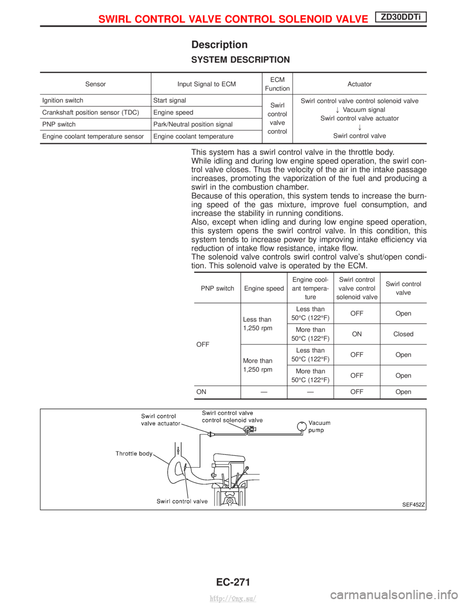
Description
SYSTEM DESCRIPTION
SensorInput Signal to ECM ECM
Function Actuator
Ignition switch Start signal Swirl
control valve
control Swirl control valve control solenoid valve
"Vacuum signal
Swirl control valve actuator "
Swirl control valve
Crankshaft position sensor (TDC) Engine speed
PNP switch Park/Neutral position signal
Engine coolant temperature sensor Engine coolant temperature
This system has a swirl control valve in the throttle body.
While idling and during low engine speed operation, the swirl con-
trol valve closes. Thus the velocity of the air in the intake passage
increases, promoting the vaporization of the fuel and producing a
swirl in the combustion chamber.
Because of this operation, this system tends to increase the burn-
ing speed of the gas mixture, improve fuel consumption, and
increase the stability in running conditions.
Also, except when idling and during low engine speed operation,
this system opens the swirl control valve. In this condition, this
system tends to increase power by improving intake efficiency via
reduction of intake flow resistance, intake flow.
The solenoid valve controls swirl control valve's shut/open condi-
tion. This solenoid valve is operated by the ECM.
PNP switch Engine speed
Engine cool-
ant tempera- ture Swirl control
valve control
solenoid valve Swirl control
valve
OFF Less than
1,250 rpm
Less than
50ÉC (122ÉF) OFF Open
More than
50ÉC (122ÉF) ON Closed
More than
1,250 rpm Less than
50ÉC (122ÉF) OFF Open
More than
50ÉC (122ÉF) OFF Open
ON Ð Ð OFF Open
SEF452Z
SWIRL CONTROL VALVE CONTROL SOLENOID VALVEZD30DDTi
EC-271
http://vnx.su/
Page 547 of 1833

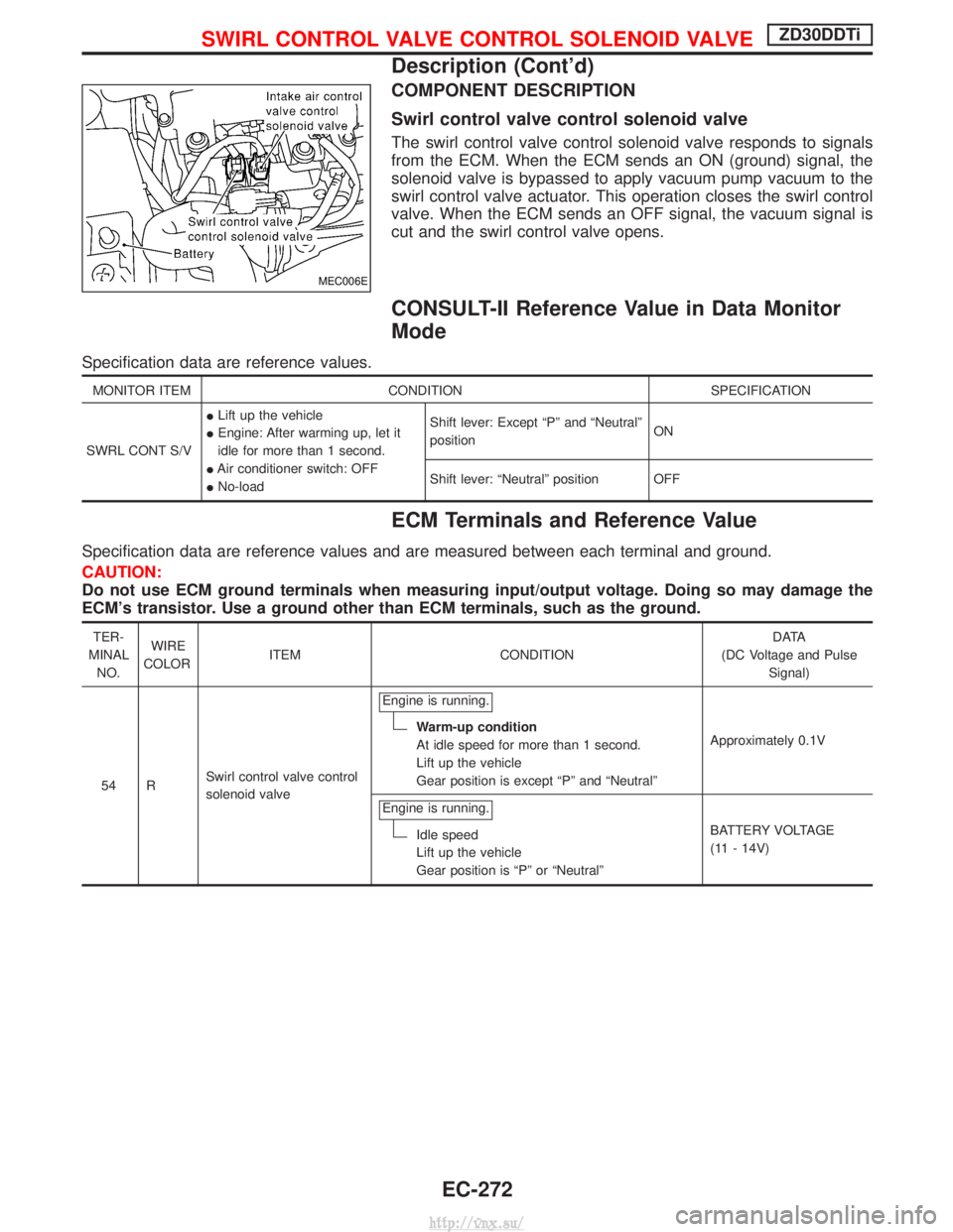
COMPONENT DESCRIPTION
Swirl control valve control solenoid valve
The swirl control valve control solenoid valve responds to signals
from the ECM. When the ECM sends an ON (ground) signal, the
solenoid valve is bypassed to apply vacuum pump vacuum to the
swirl control valve actuator. This operation closes the swirl control
valve. When the ECM sends an OFF signal, the vacuum signal is
cut and the swirl control valve opens.
CONSULT-II Reference Value in Data Monitor
Mode
Specification data are reference values.
MONITOR ITEMCONDITION SPECIFICATION
SWRL CONT S/V I
Lift up the vehicle
I Engine: After warming up, let it
idle for more than 1 second.
I Air conditioner switch: OFF
I No-load Shift lever: Except ªPº and ªNeutralº
position
ON
Shift lever: ªNeutralº position OFF
ECM Terminals and Reference Value
Specification data are reference values and are measured between each terminal and ground.
CAUTION:
Do not use ECM ground terminals when measuring input/output voltage. Doing so may damage the
ECM's transistor. Use a ground other than ECM terminals, such as the ground.
TER-
MINAL NO. WIRE
COLOR ITEM CONDITION D ATA
(DC Voltage and Pulse Signal)
54 R Swirl control valve control
solenoid valve Engine is running.
Warm-up condition
At idle speed for more than 1 second.
Lift up the vehicle
Gear position is except ªPº and ªNeutralº
Approximately 0.1V
Engine is running.
Idle speed
Lift up the vehicle
Gear position is ªPº or ªNeutralº BATTERY VOLTAGE
(11 - 14V)
MEC006E
SWIRL CONTROL VALVE CONTROL SOLENOID VALVEZD30DDTi
Description (Cont'd)
EC-272
http://vnx.su/
Page 555 of 1833

11 DETECT MALFUNCTIONING PART
Check the following.
IHarness connectors E227, F106
I Harness connectors F135, M842 (RHD models)
I Harness for open or short between swirl control valve control solenoid valve and ECM
ERepair open circuit or short to ground or short to power in harness or connectors.
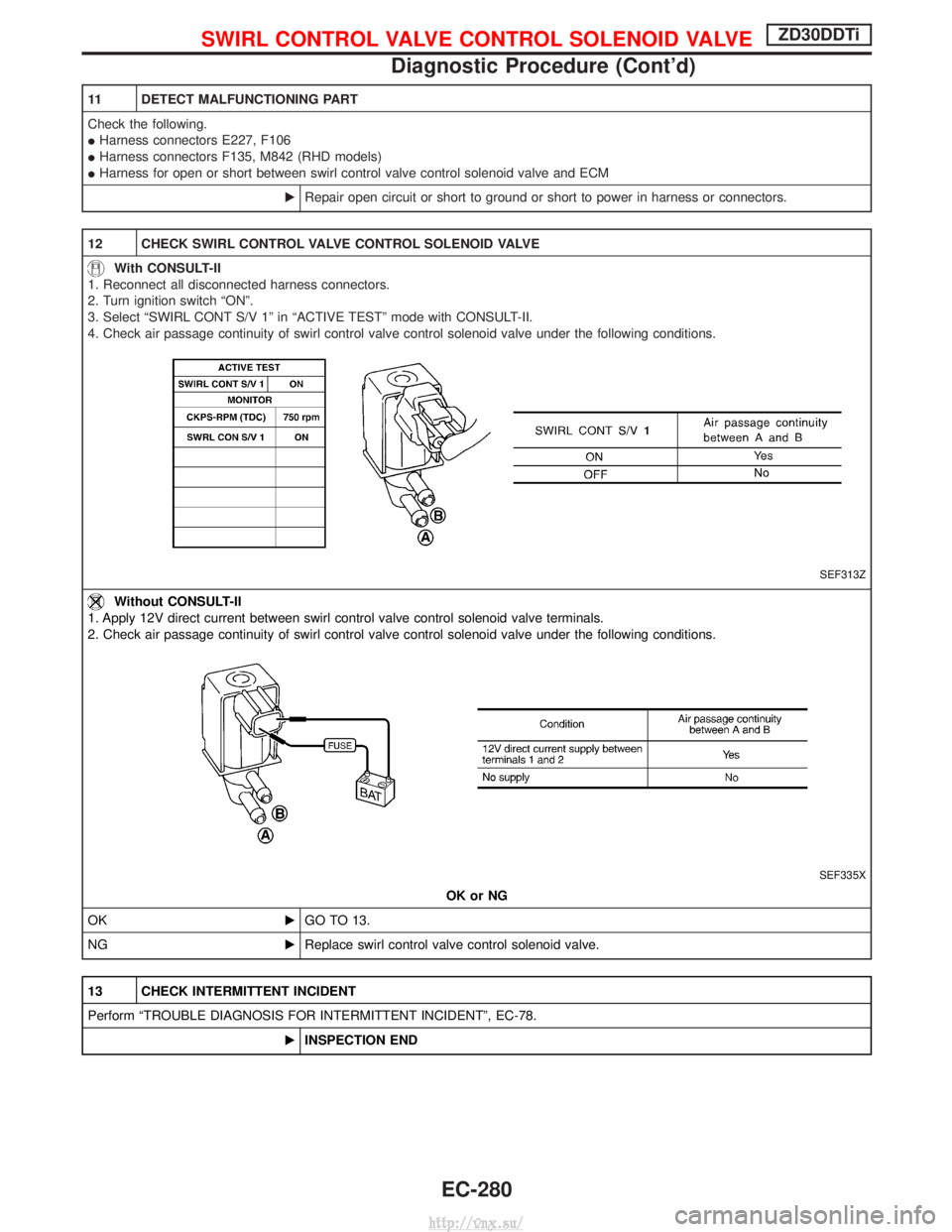
12 CHECK SWIRL CONTROL VALVE CONTROL SOLENOID VALVE
With CONSULT-II
1. Reconnect all disconnected harness connectors.
2. Turn ignition switch ªONº.
3. Select ªSWIRL CONT S/V 1º in ªACTIVE TESTº mode with CONSULT-II.
4. Check air passage continuity of swirl control valve control solenoid valve under the following conditions.
SEF313Z
Without CONSULT-II
1. Apply 12V direct current between swirl control valve control solenoid valve terminals.
2. Check air passage continuity of swirl control valve control solenoid valve under the following conditions.
SEF335X
OK or NG
OK EGO TO 13.
NG EReplace swirl control valve control solenoid valve.
13 CHECK INTERMITTENT INCIDENT
Perform ªTROUBLE DIAGNOSIS FOR INTERMITTENT INCIDENTº, EC-78.
EINSPECTION END
SWIRL CONTROL VALVE CONTROL SOLENOID VALVEZD30DDTi
Diagnostic Procedure (Cont'd)
EC-280
http://vnx.su/
Page 556 of 1833

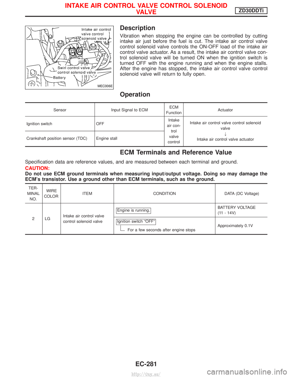
Description
Vibration when stopping the engine can be controlled by cutting
intake air just before the fuel is cut. The intake air control valve
control solenoid valve controls the ON-OFF load of the intake air
control valve actuator. As a result, the intake air control valve con-
trol solenoid valve will be turned ON when the ignition switch is
turned OFF with the engine running and when the engine stalls.
After the engine has stopped, the intake air control valve control
solenoid valve will return to fully open.
Operation
SensorInput Signal to ECM ECM
Function Actuator
Ignition switch OFF Intake
air con- trol
valve
control Intake air control valve control solenoid
valve"
Intake air control valve actuator
Crankshaft position sensor (TDC) Engine stall
ECM Terminals and Reference Value
Specification data are reference values, and are measured between each terminal and ground.
CAUTION:
Do not use ECM ground terminals when measuring input/output voltage. Doing so may damage the
ECM's transistor. Use a ground other than ECM terminals, such as the ground.
TER-
MINAL NO. WIRE
COLOR ITEM CONDITION DATA (DC Voltage)
2LG Intake air control valve
control solenoid valve Engine is running.
BATTERY VOLTAGE
(11 - 14V)
Ignition switch ªOFFº
For a few seconds after engine stops Approximately 0.1V
MEC006E
INTAKE AIR CONTROL VALVE CONTROL SOLENOID
VA LV EZD30DDTi
EC-281
http://vnx.su/
Page 558 of 1833
Diagnostic Procedure
1 CHECK OVERALL FUNCTION
1. Start engine and let it idle.
2. Make sure that intake air control valve actuator rod moves when turning ignition switch ªOFFº.
MEC011E
OK or NG
OK EINSPECTION END
NG EGO TO 2.
2 CHECK VACUUM SOURCE
1. Turn ignition switch ªOFFº.
2. Disconnect vacuum hose connected to intake air control valve actuator.
3. Start engine and let it idle.
4. Check vacuum hose for vacuum existence under the following conditions.
MEC012E
MTBL1328
OK or NG
OK EGO TO 3.
NG EGO TO 4.
INTAKE AIR CONTROL VALVE CONTROL SOLENOID
VA LV EZD30DDTi
EC-283
http://vnx.su/
Page 563 of 1833
13 CHECK INTAKE AIR CONTROL VALVE CONTROL SOLENOID VALVE
1. Apply 12V direct current between intake air control valve control solenoid valve terminals.
2. Check air passage continuity of intake air control valve control solenoid valve under the following conditions.
SEF335X
OK or NG
OK EGO TO 14.
NG EReplace intake control valve control solenoid valve.
14 CHECK INTERMITTENT INCIDENT
Perform ªTROUBLE DIAGNOSIS FOR INTERMITTENT INCIDENTº, EC-78.
EINSPECTION END
INTAKE AIR CONTROL VALVE CONTROL SOLENOID
VA LV EZD30DDTi
Diagnostic Procedure (Cont'd)
EC-288
http://vnx.su/
Page 564 of 1833
Description
The load from the variable nozzle turbocharger control solenoid
valve controls the actuator. By changing the variable nozzle vane
opening through the rods, the intake air volume is adjusted.
The variable nozzle turbocharger control solenoid valve is moved
by ON/OFF pulse from the ECM. The longer the ON pulse, the
charge air pressure rises.
CONSULT-II Reference Value in Data Monitor
Mode
Specification data are reference values.
MONITOR ITEMCONDITION SPECIFICATION
VNT S/V 1 I
Engine: After warming up
I Air conditioner switch: ªOFFº
I Shift lever: Neutral position
I No-load Idle Approx. 56%
2,000 rpm
Approx. 20%
SEF453Z
MEC014E
VARIABLE NOZZLE TURBOCHARGER CONTROL
SOLENOID VALVEZD30DDTi
EC-289
http://vnx.su/