2004 NISSAN TERRANO air condition
[x] Cancel search: air conditionPage 279 of 1833

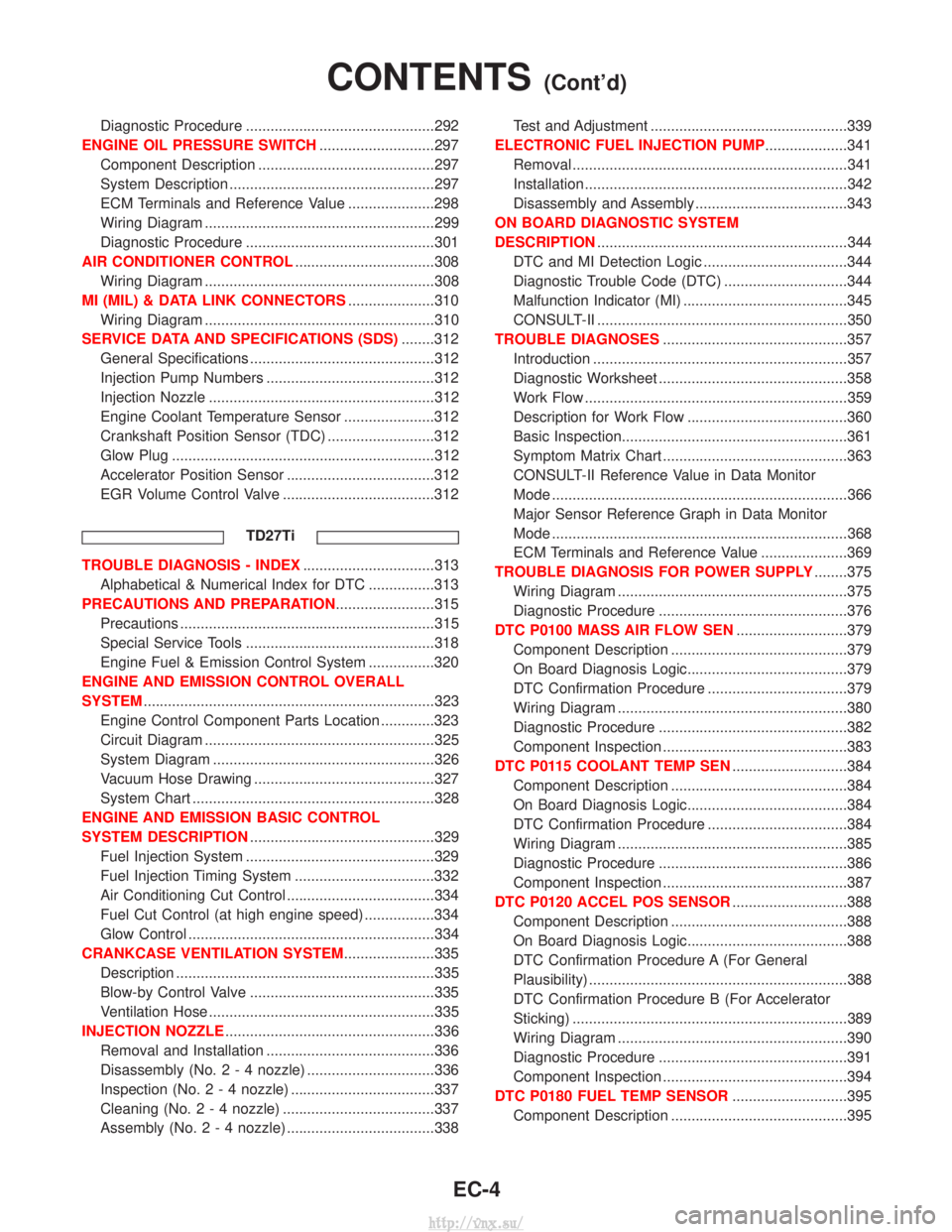
Diagnostic Procedure ..............................................292
ENGINE OIL PRESSURE SWITCH ............................297
Component Description ...........................................297
System Description ..................................................297
ECM Terminals and Reference Value .....................298
Wiring Diagram ........................................................299
Diagnostic Procedure ..............................................301
AIR CONDITIONER CONTROL ..................................308
Wiring Diagram ........................................................308
MI (MIL) & DATA LINK CONNECTORS .....................310
Wiring Diagram ........................................................310
SERVICE DATA AND SPECIFICATIONS (SDS) ........312
General Specifications .............................................312
Injection Pump Numbers .........................................312
Injection Nozzle .......................................................312
Engine Coolant Temperature Sensor ......................312
Crankshaft Position Sensor (TDC) ..........................312
Glow Plug ................................................................312
Accelerator Position Sensor ....................................312
EGR Volume Control Valve .....................................312
TD27Ti
TROUBLE DIAGNOSIS - INDEX ................................313
Alphabetical & Numerical Index for DTC ................313
PRECAUTIONS AND PREPARATION ........................315
Precautions ..............................................................315
Special Service Tools ..............................................318
Engine Fuel & Emission Control System ................320
ENGINE AND EMISSION CONTROL OVERALL
SYSTEM .......................................................................323
Engine Control Component Parts Location .............323
Circuit Diagram ........................................................325
System Diagram ......................................................326
Vacuum Hose Drawing ............................................327
System Chart ...........................................................328
ENGINE AND EMISSION BASIC CONTROL
SYSTEM DESCRIPTION .............................................329
Fuel Injection System ..............................................329
Fuel Injection Timing System ..................................332
Air Conditioning Cut Control ....................................334
Fuel Cut Control (at high engine speed) .................334
Glow Control ............................................................334
CRANKCASE VENTILATION SYSTEM ......................335
Description ...............................................................335
Blow-by Control Valve .............................................335
Ventilation Hose .......................................................335
INJECTION NOZZLE ...................................................336
Removal and Installation .........................................336
Disassembly (No.2-4 nozzle) ...............................336
Inspection (No.2-4 nozzle) ...................................337
Cleaning (No.2-4 nozzle) .....................................337
Assembly (No.2-4 nozzle) ....................................338 Test and Adjustment ................................................339
ELECTRONIC FUEL INJECTION PUMP ....................341
Removal ...................................................................341
Installation ................................................................342
Disassembly and Assembly .....................................343
ON BOARD DIAGNOSTIC SYSTEM
DESCRIPTION .............................................................344
DTC and MI Detection Logic ...................................344
Diagnostic Trouble Code (DTC) ..............................344
Malfunction Indicator (MI) ........................................345
CONSULT-II .............................................................350
TROUBLE DIAGNOSES .............................................357
Introduction ..............................................................357
Diagnostic Worksheet ..............................................358
Work Flow ................................................................359
Description for Work Flow .......................................360
Basic Inspection.......................................................361
Symptom Matrix Chart .............................................363
CONSULT-II Reference Value in Data Monitor
Mode ........................................................................\
366
Major Sensor Reference Graph in Data Monitor
Mode ........................................................................\
368
ECM Terminals and Reference Value .....................369
TROUBLE DIAGNOSIS FOR POWER SUPPLY ........375
Wiring Diagram ........................................................375
Diagnostic Procedure ..............................................376
DTC P0100 MASS AIR FLOW SEN ...........................379
Component Description ...........................................379
On Board Diagnosis Logic.......................................379
DTC Confirmation Procedure ..................................379
Wiring Diagram ........................................................380
Diagnostic Procedure ..............................................382
Component Inspection .............................................383
DTC P0115 COOLANT TEMP SEN ............................384
Component Description ...........................................384
On Board Diagnosis Logic.......................................384
DTC Confirmation Procedure ..................................384
Wiring Diagram ........................................................385
Diagnostic Procedure ..............................................386
Component Inspection .............................................387
DTC P0120 ACCEL POS SENSOR ............................388
Component Description ...........................................388
On Board Diagnosis Logic.......................................388
DTC Confirmation Procedure A (For General
Plausibility) ...............................................................388
DTC Confirmation Procedure B (For Accelerator
Sticking) ...................................................................389
Wiring Diagram ........................................................390
Diagnostic Procedure ..............................................391
Component Inspection .............................................394
DTC P0180 FUEL TEMP SENSOR ............................395
Component Description ...........................................395
CONTENTS(Cont'd)
EC-4
http://vnx.su/
Page 280 of 1833

On Board Diagnosis Logic.......................................395
DTC Confirmation Procedure ..................................395
Wiring Diagram ........................................................396
Diagnostic Procedure ..............................................397
Component Inspection .............................................398
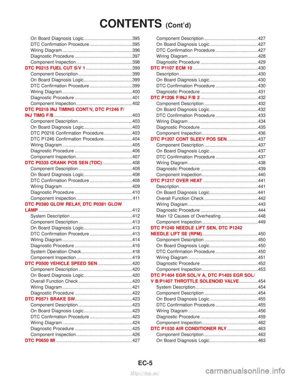
DTC P0215 FUEL CUT S/V 1 .....................................399
Component Description ...........................................399
On Board Diagnosis Logic.......................................399
DTC Confirmation Procedure ..................................399
Wiring Diagram ........................................................400
Diagnostic Procedure ..............................................401
Component Inspection .............................................402
DTC P0216 INJ TIMING CONT/V, DTC P1246 F/
INJ TIMG F/B ...............................................................403
Component Description ...........................................403
On Board Diagnosis Logic.......................................403
DTC P0216 Confirmation Procedure.......................403
DTC P1246 Confirmation Procedure.......................404
Wiring Diagram ........................................................405
Diagnostic Procedure ..............................................406
Component Inspection .............................................407
DTC P0335 CRANK POS SEN (TDC) ........................408
Component Description ...........................................408
On Board Diagnosis Logic.......................................408
DTC Confirmation Procedure ..................................408
Wiring Diagram ........................................................409
Diagnostic Procedure ..............................................410
Component Inspection ............................................. 411
DTC P0380 GLOW RELAY, DTC P0381 GLOW
LAMP ........................................................................\
...412
System Description ..................................................412
Component Description ...........................................413
On Board Diagnosis Logic.......................................413
DTC Confirmation Procedure ..................................413
Wiring Diagram ........................................................414
Diagnostic Procedure ..............................................416
System Operation Check.........................................418
Component Inspection .............................................419
DTC P0500 VEHICLE SPEED SEN ............................420
Component Description ...........................................420
On Board Diagnosis Logic.......................................420
Overall Function Check ...........................................420
Wiring Diagram ........................................................421
Diagnostic Procedure ..............................................422
DTC P0571 BRAKE SW ..............................................423
Component Description ...........................................423
On Board Diagnosis Logic.......................................423
DTC Confirmation Procedure ..................................423
Wiring Diagram ........................................................424
Diagnostic Procedure ..............................................425
Component Inspection .............................................426
DTC P0650 MI .............................................................427 Component Description ...........................................427
On Board Diagnosis Logic.......................................427
DTC Confirmation Procedure ..................................427
Wiring Diagram ........................................................428
Diagnostic Procedure ..............................................429
DTC P1107 ECM 10 ....................................................430
Description ...............................................................430
On Board Diagnosis Logic.......................................430
DTC Confirmation Procedure ..................................430
Diagnostic Procedure ..............................................431
DTC P1206 F/INJ F/B 2 ..............................................432
Component Description ...........................................432
On Board Diagnosis Logic.......................................432
DTC Confirmation Procedure ..................................433
Wiring Diagram ........................................................434
Diagnostic Procedure ..............................................435
Component Inspection .............................................436
DTC P1207 CONT SLEEV POS SEN .........................437
Component Description ...........................................437
On Board Diagnosis Logic.......................................437
DTC Confirmation Procedure ..................................437
Wiring Diagram ........................................................438
Diagnostic Procedure ..............................................439
Component Inspection .............................................440
DTC P1217 OVER HEAT ............................................441
Description ...............................................................441
On Board Diagnosis Logic.......................................441
Overall Function Check ...........................................442
Wiring Diagram ........................................................443
Diagnostic Procedure ..............................................444
Main 12 Causes of Overheating..............................448
Component Inspection .............................................449
DTC P1240 NEEDLE LIFT SEN, DTC P1242
NEEDLE LIFT SE (RPM) .............................................450
Component Description ...........................................450
On Board Diagnosis Logic.......................................450
DTC Confirmation Procedure ..................................450
Wiring Diagram ........................................................451
Diagnostic Procedure ..............................................452
Component Inspection .............................................453
DTC P1404 EGR SOL/V A, DTC P1405 EGR SOL/
V B/P1407 THROTTLE SOLENOID VALVE ...............454
System Description ..................................................454
Component Description ...........................................454
On Board Diagnosis Logic.......................................455
DTC Confirmation Procedure ..................................455
Wiring Diagram ........................................................456
Diagnostic Procedure ..............................................459
Component Inspection .............................................462
DTC P1530 AIR CONDITIONER RLY .........................463
Component Description ...........................................463
On Board Diagnosis Logic.......................................463
CONTENTS(Cont'd)
EC-5
http://vnx.su/
Page 294 of 1833

System Chart
Input (Sensor)ECM FunctionOutput (Actuator)
I Electronic control fuel injection pump
I Crankshaft position sensor (TDC)
I Engine coolant temperature sensor
I Accelerator position sensor
I Accelerator position switch
I Accelerator switch (F/C)
I Park/Neutral position (PNP) switch
I Ignition switch
I Battery voltage
I Vehicle speed sensor
I Air conditioner switch
I Mass air flow sensor
I Stop lamp switch
I Heat up switch
I Charge air pressure sensor*1 Fuel injection control
Electronic control fuel injection pump
Fuel injection timing control Electronic control fuel injection pump
Fuel cut control Electronic control fuel injection pump
Glow control system Glow relay & glow lamp
On board diagnostic system MI (On the instrument panel)
EGR volume control EGR volume control valve
Cooling fan control Cooling fan relay
Air conditioning cut control Air conditioner relay
Variable nozzle turbocharger control Variable nozzle turbocharger control sole- noid valve
Swirl control valve control Swirl control valve control solenoid valve
Intake air control valve control Intake air control valve control solenoid
valve
*1: This sensor is not used to control the engine system under normal conditions.
ENGINE AND EMISSION CONTROL OVERALL SYSTEMZD30DDTi
EC-19
http://vnx.su/
Page 295 of 1833

Fuel Injection Control System
DESCRIPTION
System description
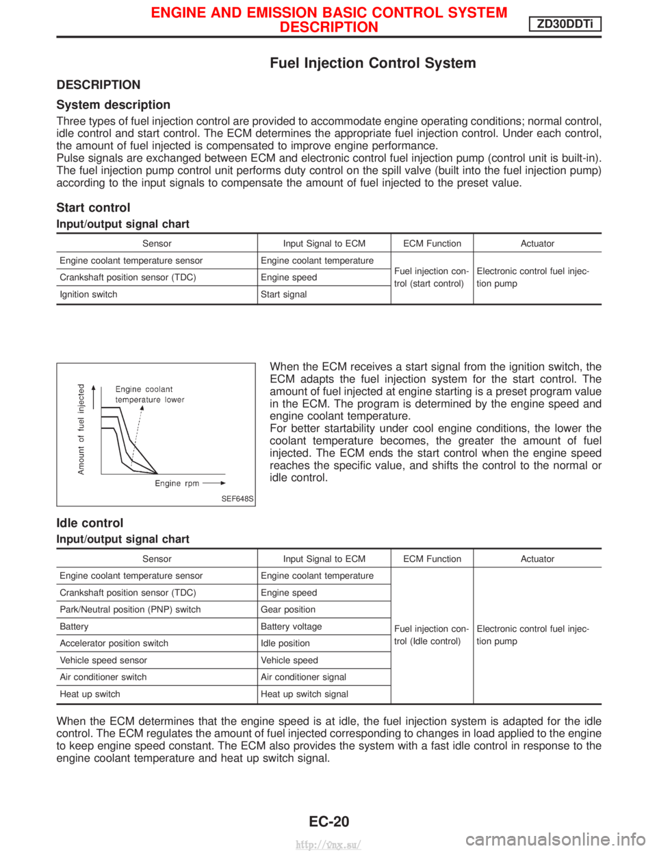
Three types of fuel injection control are provided to accommodate engine operating conditions; normal control,
idle control and start control. The ECM determines the appropriate fuel injection control. Under each control,
the amount of fuel injected is compensated to improve engine performance.
Pulse signals are exchanged between ECM and electronic control fuel injection pump (control unit is built-in).
The fuel injection pump control unit performs duty control on the spill valve (built into the fuel injection pump)
according to the input signals to compensate the amount of fuel injected to the preset value.
Start control
Input/output signal chart
SensorInput Signal to ECM ECM Function Actuator
Engine coolant temperature sensor Engine coolant temperature
Fuel injection con-
trol (start control)Electronic control fuel injec-
tion pump
Crankshaft position sensor (TDC)
Engine speed
Ignition switch Start signal
When the ECM receives a start signal from the ignition switch, the
ECM adapts the fuel injection system for the start control. The
amount of fuel injected at engine starting is a preset program value
in the ECM. The program is determined by the engine speed and
engine coolant temperature.
For better startability under cool engine conditions, the lower the
coolant temperature becomes, the greater the amount of fuel
injected. The ECM ends the start control when the engine speed
reaches the specific value, and shifts the control to the normal or
idle control.
Idle control
Input/output signal chart
SensorInput Signal to ECM ECM Function Actuator
Engine coolant temperature sensor Engine coolant temperature
Fuel injection con-
trol (Idle control)Electronic control fuel injec-
tion pump
Crankshaft position sensor (TDC)
Engine speed
Park/Neutral position (PNP) switch Gear position
Battery Battery voltage
Accelerator position switch Idle position
Vehicle speed sensor Vehicle speed
Air conditioner switch Air conditioner signal
Heat up switch Heat up switch signal
When the ECM determines that the engine speed is at idle, the fuel injection system is adapted for the idle
control. The ECM regulates the amount of fuel injected corresponding to changes in load applied to the engine
to keep engine speed constant. The ECM also provides the system with a fast idle control in response to the
engine coolant temperature and heat up switch signal.
SEF648S
ENGINE AND EMISSION BASIC CONTROL SYSTEM
DESCRIPTIONZD30DDTi
EC-20
http://vnx.su/
Page 296 of 1833

Normal control
Input/output signal chart
SensorInput Signal to ECM ECM Function Actuator
Crankshaft position sensor (TDC) Engine speed
Fuel injection con-
trol (Normal con-
trol)Electronic control fuel injec-
tion pump
Accelerator position sensor
Accelerator position
Vehicle speed sensor Vehicle speed
The amount of fuel injected under normal driving conditions is
determined according to sensor signals. The crankshaft position
sensor (TDC) detects engine speed and the accelerator position
sensor detects accelerator position. These sensors send signals to
the ECM.
The fuel injection data, predetermined by correlation between vari-
ous engine speeds and accelerator positions, are stored in the
ECM memory, forming a map. The ECM determines the optimal
amount of fuel to be injected using the sensor signals in compari-
son with the map.
Maximum amount control
Input/output signal chart
SensorInput Signal to ECM ECM Function Actuator
Mass air flow sensor Amount of intake air
Fuel injection con-
trol (Maximum
amount control)Electronic control fuel injec-
tion pump
Engine coolant temperature sensor Engine coolant temperature
Crankshaft position sensor (TDC) Engine speed
Accelerator position sensor Accelerator position
The maximum injection amount is controlled to an optimum by the engine speed, intake air amount, engine
coolant temperature, and accelerator opening in accordance with the driving conditions.
This prevents the oversupply of the injection amount caused by decreased air density at a high altitude or
during a system failure.
Deceleration control
Input/output signal chart
Sensor
Input Signal to ECM ECM Function Actuator
Accelerator switch (F/C) Accelerator positionFuel injection con-
trol (Deceleration
control)Electronic control fuel injec-
tion pump
Crankshaft position sensor (TDC) Engine speed
The ECM sends a fuel cut signal to the electronic control fuel injection pump during deceleration for better
fuel efficiency. The ECM determines the time of deceleration according to signals from the accelerator switch
(F/C) and crankshaft position sensor (TDC).
SEF649S
ENGINE AND EMISSION BASIC CONTROL SYSTEM
DESCRIPTIONZD30DDTi
Fuel Injection Control System (Cont'd)
EC-21
http://vnx.su/
Page 297 of 1833

Fuel Injection Timing Control System
DESCRIPTION
The target fuel injection timing in accordance with the engine speed and the fuel injection amount are recorded
as a map in the ECM beforehand. The ECM and the injection pump control unit exchange signals and per-
form feedback control for optimum injection timing in accordance with the map.
Air Conditioning Cut Control
DESCRIPTION
Input/output signal chart
SensorInput Signal to ECM ECM Function Actuator
Air conditioner switch Air conditioner ªONº signal
Air conditioner cut
controlAir conditioner relay
Accelerator position sensor
Accelerator valve opening
angle
Vehicle speed sensor Vehicle speed
Engine coolant temperature sensor Engine coolant temperature
System description
This system improves acceleration when the air conditioner is used.
When the accelerator pedal is fully depressed, the air conditioner is turned off for a few seconds.
When engine coolant temperature becomes excessively high, the air conditioner is turned off. This continues
until the engine coolant temperature returns to normal.
Fuel Cut Control (at no load & high engine
speed)
DESCRIPTION
Input/output signal chart
SensorInput Signal to ECM ECM Function Actuator
Vehicle speed sensor Vehicle speed
Fuel cut controlElectronic control fuel injec-
tion pump
Park/Neutral position (PNP) switch
Neutral position
Accelerator position switch or Accelerator
switch (F/C) Accelerator position
Engine coolant temperature sensor Engine coolant temperature
Crankshaft position sensor (TDC) Engine speed
If the engine speed is above 2,700 rpm with no load (for example, in neutral and engine speed over 2,700
rpm) fuel will be cut off after some time. The exact time when the fuel is cut off varies based on engine speed.
Fuel cut will operate until the engine speed reaches 1,500 rpm, then fuel cut is cancelled.
NOTE:
This function is different from deceleration control listed under ªFuel Injection Control Systemº, EC-20.
ENGINE AND EMISSION BASIC CONTROL SYSTEM
DESCRIPTIONZD30DDTi
EC-22
http://vnx.su/
Page 315 of 1833

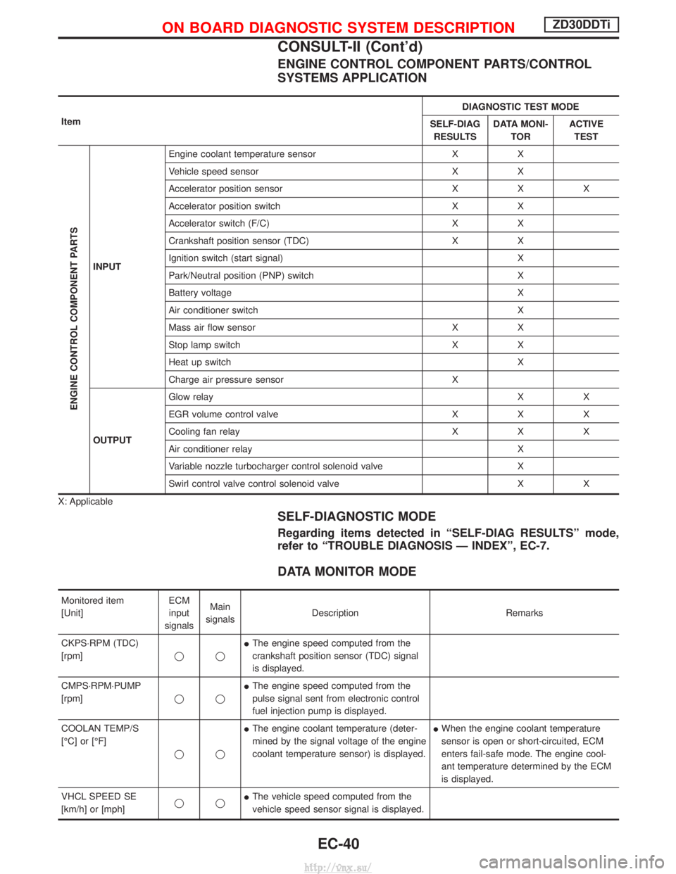
ENGINE CONTROL COMPONENT PARTS/CONTROL
SYSTEMS APPLICATION
ItemDIAGNOSTIC TEST MODE
SELF-DIAG RESULTS DATA MONI-
TOR ACTIVE
TEST
ENGINE CONTROL COMPONENT PARTS
INPUT Engine coolant temperature sensor X X
Vehicle speed sensor X X
Accelerator position sensor X X X
Accelerator position switch X X
Accelerator switch (F/C) X X
Crankshaft position sensor (TDC) X X
Ignition switch (start signal) X
Park/Neutral position (PNP) switch X
Battery voltage X
Air conditioner switch X
Mass air flow sensor X X
Stop lamp switch X X
Heat up switch X
Charge air pressure sensor X
OUTPUT Glow relay
XX
EGR volume control valve X X X
Cooling fan relay X X X
Air conditioner relay X
Variable nozzle turbocharger control solenoid valve X
Swirl control valve control solenoid valve X X
X: Applicable
SELF-DIAGNOSTIC MODE
Regarding items detected in ªSELF-DIAG RESULTSº mode,
refer to ªTROUBLE DIAGNOSIS Ð INDEXº, EC-7.
DATA MONITOR MODE
Monitored item
[Unit] ECM
input
signals Main
signals Description Remarks
CKPS×RPM (TDC)
[rpm] qqI
The engine speed computed from the
crankshaft position sensor (TDC) signal
is displayed.
CMPS×RPM×PUMP
[rpm] qqI
The engine speed computed from the
pulse signal sent from electronic control
fuel injection pump is displayed.
COOLAN TEMP/S
[ÉC] or [ÉF] qqI
The engine coolant temperature (deter-
mined by the signal voltage of the engine
coolant temperature sensor) is displayed. I
When the engine coolant temperature
sensor is open or short-circuited, ECM
enters fail-safe mode. The engine cool-
ant temperature determined by the ECM
is displayed.
VHCL SPEED SE
[km/h] or [mph] qqI
The vehicle speed computed from the
vehicle speed sensor signal is displayed.
ON BOARD DIAGNOSTIC SYSTEM DESCRIPTIONZD30DDTi
CONSULT-II (Cont'd)
EC-40
http://vnx.su/
Page 316 of 1833
![NISSAN TERRANO 2004 Service Repair Manual Monitored item
[Unit]ECM
input
signals Main
signals Description Remarks
FUEL TEMP SEN
[ÉC] or [ÉF] qqI
The fuel temperature (sent from elec-
tronic control fuel injection pump) is dis-
played.
ACCEL NISSAN TERRANO 2004 Service Repair Manual Monitored item
[Unit]ECM
input
signals Main
signals Description Remarks
FUEL TEMP SEN
[ÉC] or [ÉF] qqI
The fuel temperature (sent from elec-
tronic control fuel injection pump) is dis-
played.
ACCEL](/manual-img/5/57394/w960_57394-315.png)
Monitored item
[Unit]ECM
input
signals Main
signals Description Remarks
FUEL TEMP SEN
[ÉC] or [ÉF] qqI
The fuel temperature (sent from elec-
tronic control fuel injection pump) is dis-
played.
ACCEL POS SEN [V] qqI
The accelerator position sensor signal
voltage is displayed.
FULL ACCEL SW
[ON/OFF] qqI
Indicates [ON/OFF] condition from the
accelerator position switch signal.
ACCEL SW (FC)
[OPEN/CLOSE] qqI
Indicates [OPEN/CLOSE] condition from
the accelerator switch (FC) signal.
OFF ACCEL SW
[ON/OFF] qqI
Indicates [ON/OFF] condition from the
accelerator position switch signal.
SPILL/V [ÉCA] qI
The control position of spill valve (sent
from electronic control fuel injection
pump) is displayed.
BATTERY VOLT [V] qqI
The power supply voltage of ECM is dis-
played.
P/N POSI SW
[ON/OFF] qqI
Indicates [ON/OFF] condition from the
park/neutral position switch signal.
START SIGNAL
[ON/OFF] qqI
Indicates [ON/OFF] condition from the
starter signal. I
After starting the engine, [OFF] is dis-
played regardless of the starter signal.
AIR COND SIG
[ON/OFF] qqI
Indicates [ON/OFF] condition of the air
conditioner switch as determined by the
air conditioner signal.
BRAKE SW [ON/OFF] qqI
Indicates [ON/OFF] condition from the
stop lamp switch signal.
IGN SW
[ON/OFF] qqI
Indicates [ON/OFF] condition from igni-
tion switch signal.
WARM UP SW
[ON/OFF] qI
Indicates [ON/OFF] condition from the
heat up switch signal.
MAS AIR/FL SE [V] qqI
The signal voltage of the mass air flow
sensor is displayed. I
When the engine is stopped, a certain
value is indicated.
DECELER F/CUT
[ON/OFF] qI
The [ON/OFF] condition from decelera-
tion fuel cut signal (sent from electronic
control fuel injection pump) is displayed.
INJ TIMG C/V [%] qI
The duty ratio of fuel injection timing
control valve (sent from electronic control
fuel injection pump) is displayed.
AIR COND RLY
[ON/OFF] qI
Indicates the control condition of the air
conditioner relay (determined by ECM
according to the input signals).
GLOW RLY [ON/OFF] qI
The glow relay control condition (deter-
mined by ECM according to the input
signal) is displayed.
COOLING FAN
[ON/OFF] qI
Indicates the control condition of the
cooling fans (determined by ECM
according to the input signal).
I ON ... Operates.
OFF ... Stopped.
ON BOARD DIAGNOSTIC SYSTEM DESCRIPTIONZD30DDTi
CONSULT-II (Cont'd)
EC-41
http://vnx.su/