Page 57 of 1833
Maintenance for off-road driving
Whenever you drive off-road through sand, mud or water as deep as the wheel hub, more frequent mainte-
nance may be required of the following items:
GBrake pads and discs
G Brake lining and drums
G Brake lines and hoses
G Wheel bearing grease and free-running hub grease
G Differential, transmission and transfer oil
G Steering linkage
G Propeller shafts and front drive shafts
G Air cleaner filter
Clutch housing (Check water entry.)
PERIODIC MAINTENANCE
Maintenance Under Severe Driving Conditions
(annual mileage > 30,000 km/year) (Cont'd)
MA-16
http://vnx.su/
Page 58 of 1833

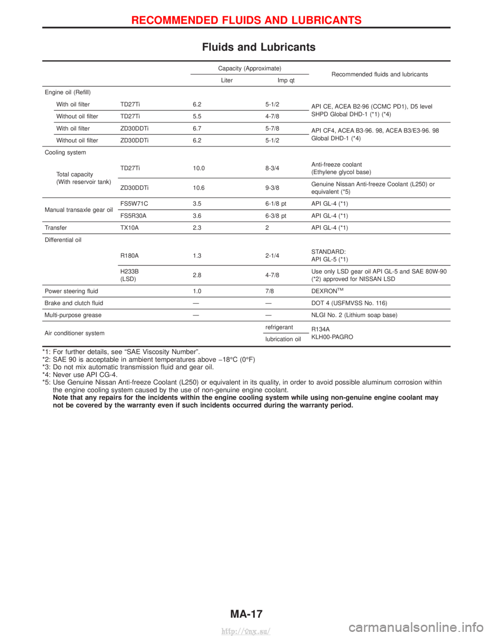
Fluids and Lubricants
Capacity (Approximate)Recommended fluids and lubricants
Liter Imp qt
Engine oil (Refill) With oil filter TD27Ti 6.2 5-1/2 API CE, ACEA B2-96 (CCMC PD1), D5 level
SHPD Global DHD-1 (*1) (*4)
Without oil filter TD27Ti 5.5 4-7/8
With oil filter ZD30DDTi 6.7 5-7/8 API CF4, ACEA B3-96. 98, ACEA B3/E3-96. 98
Global DHD-1 (*4)
Without oil filter ZD30DDTi 6.2 5-1/2
Cooling system
Total capacity
(With reservoir tank) TD27Ti 10.0 8-3/4
Anti-freeze coolant
(Ethylene glycol base)
ZD30DDTi 10.6 9-3/8 Genuine Nissan Anti-freeze Coolant (L250) or
equivalent (*5)
Manual transaxle gear oil FS5W71C 3.5 6-1/8 pt API GL-4 (*1)
FS5R30A 3.6 6-3/8 pt API GL-4 (*1)
Transfer TX10A 2.3 2 API GL-4 (*1)
Differential oil
R180A 1.3 2-1/4 STANDARD:
API GL-5 (*1)
H233B
(LSD) 2.8 4-7/8 Use only LSD gear oil API GL-5 and SAE 80W-90
(*2) approved for NISSAN LSD
Power steering fluid 1.0 7/8 DEXRON
TM
Brake and clutch fluid ÐÐDOT 4 (USFMVSS No. 116)
Multi-purpose grease Ð Ð NLGI No. 2 (Lithium soap base)
Air conditioner system refrigerant
R134A
KLH00-PAGRO
lubrication oil
*1: For further details, see ªSAE Viscosity Numberº.
*2: SAE 90 is acceptable in ambient temperatures above þ18ÉC (0ÉF)
*3: Do not mix automatic transmission fluid and gear oil.
*4: Never use API CG-4.
*5: Use Genuine Nissan Anti-freeze Coolant (L250) or equivalent in its quality, in order to avoid possible aluminum corrosion within
the engine cooling system caused by the use of non-genuine engine coolant.
Note that any repairs for the incidents within the engine cooling system while using non-genuine engine coolant may
not be covered by the warranty even if such incidents occurred during the warranty period.
RECOMMENDED FLUIDS AND LUBRICANTS
MA-17
http://vnx.su/
Page 61 of 1833

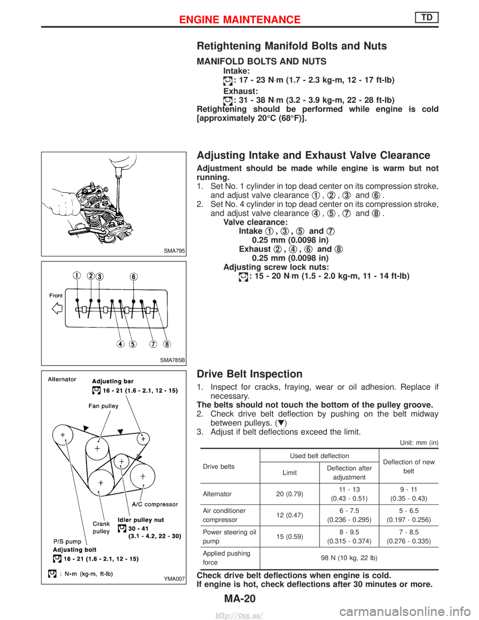
Retightening Manifold Bolts and Nuts
MANIFOLD BOLTS AND NUTS
Intake:
:17-23N×m (1.7 - 2.3 kg-m, 12 - 17 ft-lb)
Exhaust:
:31-38N ×m (3.2 - 3.9 kg-m, 22 - 28 ft-lb)
Retightening should be performed while engine is cold
[approximately 20ÉC (68ÉF)].
Adjusting Intake and Exhaust Valve Clearance
Adjustment should be made while engine is warm but not
running.
1. Set No. 1 cylinder in top dead center on its compression stroke, and adjust valve clearance q
1,q2,q3and q6.
2. Set No. 4 cylinder in top dead center on its compression stroke, and adjust valve clearance q
4,q5,q7and q8.
Valve clearance: Intake q
1,q3,q5and q7
0.25 mm (0.0098 in)
Exhaust q
2,q4,q6and q8
0.25 mm (0.0098 in)
Adjusting screw lock nuts:
:15-20N ×m (1.5 - 2.0 kg-m, 11 - 14 ft-lb)
Drive Belt Inspection
1. Inspect for cracks, fraying, wear or oil adhesion. Replace if
necessary.
The belts should not touch the bottom of the pulley groove.
2. Check drive belt deflection by pushing on the belt midway between pulleys. (H)
3. Adjust if belt deflections exceed the limit.
Unit: mm (in)
Drive belts Used belt deflection
Deflection of new
belt
Limit Deflection after
adjustment
Alternator 20 (0.79) 11-13
(0.43 - 0.51) 9-11
(0.35 - 0.43)
Air conditioner
compressor 12 (0.47)6 - 7.5
(0.236 - 0.295) 5 - 6.5
(0.197 - 0.256)
Power steering oil
pump 15 (0.59)8 - 9.5
(0.315 - 0.374) 7 - 8.5
(0.276 - 0.335)
Applied pushing
force 98 N (10 kg, 22 lb)
Check drive belt deflections when engine is cold.
If engine is hot, check deflections after 30 minutes or more.
SMA795
SMA785B
YMA007
ENGINE MAINTENANCETD
MA-20
http://vnx.su/
Page 67 of 1833

Checking Idle Speed
Preparation
1. Make sure that injection timing is correct.
2. Make sure that injection nozzle are in good condition.
3. Make sure that the following parts are in good condition.
IAir cleaner clogging
I Glow system
I Engine oil and coolant levels
I Valve clearance
I Air intake system (Oil filler cap, oil level gauge, etc.)
4. Set shift lever in ªNeutralº position. Engage parking brake and lock both front and rear wheels with wheel chocks.
5. Turn off air conditioner, lights and accessories.
I Warm up engine until water temperature indicator points to middle of gauge.
I Lights, heater fan and all accessories are off.
I Attach tachometer's pick-up to No. 1 fuel injection tube.
In order to take accurate reading of engine rpm, remove clamps that secure No. 1 fuel injection tube.
Start engine.
SMA406B
SMA021A
Run engine at about 2,000 rpm for
about 2 minutes under no-load.
Run engine for one minute at idle
speed.F
Check idle speed.
---------------------------------------------------------------------------------------------------------------------------------------------------------------------------------------------------------------------------------- IDLE SPEED: 700+ 50 rpm
OK
ENG Adjust idle speed by turning idle speed adjust-
ing screw.
EMA049
END
I
Race engine two or three times and allow engine to return to idle speed. If idle speed is not within
the specified range, check acceleration linkage for binding and correct it if necessary.
H
H
H
H
H
ENGINE MAINTENANCETD
MA-26
http://vnx.su/
Page 68 of 1833
AIR CONDITIONER EQUIPPED MODEL
1. Make certain that the clearance between the actuator idle con-trol lever pin and the injection pump control lever is within the
specified limits.
2. Adjust idle speed to specified rpm without the air conditioner operating.
3. Then check the idle speed when the air conditioner is operat- ing and make sure it is correct.
Unit: rpm
Idle speed (Air conditioner: ªONº) 850 50
If not, adjust it by turning FICD actuator stroke adjusting screw.
SMA794B
ENGINE MAINTENANCETD
Checking Idle Speed (Cont'd)
MA-27
http://vnx.su/
Page 70 of 1833

Removal
WATER PUMP, ALTERNATOR AND AIR CONDITIONER
BELT
1. Remove radiator shroud.
2. Contract and hold the auto tensioner using the following proce-dure.
a. Securely hold the 19 mm (0.75 in) hexagonal portion A of auto tensioner with a closed wrench.
I Preferably use a tool with a handhold of 500 mm (19.69 in) or
more in length.
I No bolts or nuts are required to be loosened during the opera-
tion.
b. Turn the hexagonal portion A in the direction shown by the arrow to contract the damper unit of the auto tensioner.
CAUTION:
I Because the tensioner has a high tension, it shall be
securely held and turned with a closed wrench.
I Because the hexagonal portion A of the tensioner is made
of aluminum and may be damaged by sudden input, turn
it slowly according to the contraction of the damper unit.
3. Remove the belt from the alternator pulley first, and then remove it from the other pulleys.
I If the tensioner is not held firmly, your finger may get caught
between the belt and the pulleys. Confirm the holding of the
tensioner, and then hold the belt side in the place away from
the pulleys to attach or remove the belt, paying attention to
prevent your finger from being caught.
CAUTION:
I When handling the belt, pay attention to prevent the oil or
coolant from adhering to the belt.
I Do not distort or bend the belt intensively.
Installation
IInstall the belt in the reverse order of removal.
I After installation of the belt, confirm that the belt engages the
pulleys securely.
I Depending on the engagement between the belt and the idler
pulley, noise (belt noise) may be heard when the engine is
started just after installation. This noise will stop with time.
Changing Engine Oil
WARNING:
IBe careful not to burn yourself, as engine oil is hot.
I Prolonged and repeated contact with used engine oil may
cause skin cancer; try to avoid direct skin contact with
used oil. If skin contact is made, wash thoroughly with
soap or hand cleaner as soon as possible.
1. Warm up engine, and check for oil leakage from engine com- ponents.
2. Remove drain plug and oil filler cap.
SMA101D
ENGINE MAINTENANCEZD
MA-29
http://vnx.su/
Page 81 of 1833
Checking Free-running Hub Grease
Check free-running hub grease for leakage and water or dust entry.
Checking Brake Fluid Level and Leaks
If fluid level is extremely low, check brake system for leaks.
Checking Brake System
Check brake fluid lines and parking brake cables for improper
attachment, leaks, chafing, abrasion, deterioration, etc.
Checking Brake Booster, Vacuum Hoses,
Connections and Check Valve
Check vacuum lines, connections and check valve for improper
attachment, air tightness, chafing and deterioration.
Checking Disc Brake
Check condition of disc brake components.
ROTOR
Check condition and thickness.Standard thickness:26 mm (1.02 in)
Minimum thickness: 24 mm (0.94 in)
SMA946B
SBR991
SMA732A
SBR402A
SMA260A
CHASSIS AND BODY MAINTENANCE
MA-40
http://vnx.su/
Page 88 of 1833
Checking Body Corrosion
Visually check the body sheet metal panel for corrosion, paint damage (scratches, chipping, rubbing, etc.) or
damage to the anti-corrosion materials. In particular, check the following locations.
Hemmed portion
Hood front end, door lower end, trunk lid rear end, etc.
Panel joint
Side sill of rear fender and center pillar, rear wheel housing of rear fender, around strut lower in engine
compartment, etc.
Panel edge
Back door lid opening, sun roof opening, fender wheel-arch flange, fuel filler lid flange, around holes in panel,
etc.
Parts contact
Waist moulding, windshield moulding, bumper, etc.
Protectors
Damage or condition of mudguard, fender protector, chipping protector, etc.
Anti-corrosion materials
Damage or separation of anti-corrosion materials under the body.
Drain holes
Condition of drain holes at door and side sill.
When repairing corroded areas, refer to the Corrosion Repair Manual.
CHASSIS AND BODY MAINTENANCE
MA-47
http://vnx.su/