Page 923 of 1833
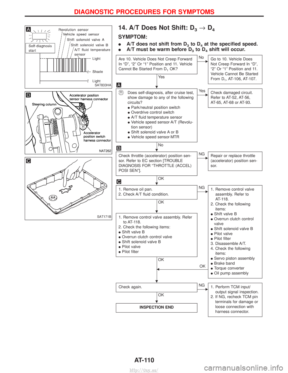
14. A/T Does Not Shift: D3®D4
SYMPTOM:
I A/T does not shift from D3to D4at the specified speed.
I A/T must be warm before D
3to D4shift will occur.
Are 10. Vehicle Does Not Creep Forward
In ªDº, ª2º Or ª1º Position and 11. Vehicle
Cannot Be Started From D
1OK?
Ye s
ENo
Go to 10. Vehicle Does
Not Creep Forward In ªDº,
ª2º Or ª1º Position and 11.
Vehicle Cannot Be Started
From D
1, AT-106, AT-107.
Does self-diagnosis, after cruise test,
show damage to any of the following
circuits?
IPark/neutral position switch
I Overdrive control switch
I A/T fluid temperature sensor
I Vehicle speed sensor×A/T (Revolu-
tion sensor)
I Shift solenoid valve A or B
I Vehicle speed sensor×MTR
No
EYe s
Check damaged circuit.
Refer to AT-52, AT-56,
AT-65, AT-68 or AT-93.
Check throttle (accelerator) position sen-
sor. Refer to EC section [TROUBLE
DIAGNOSIS FOR ªTHROTTLE (ACCEL)
POSI SENº].
OK
ENGRepair or replace throttle
(accelerator) position sen-
sor.
1. Remove oil pan.
2. Check A/T fluid condition.
OK
ENG 1. Remove control valve
assembly. Refer to
AT-118.
2. Check the following items:
I Shift valve B
I Overrun clutch control
valve
I Shift solenoid valve B
I Pilot valve
I Pilot filter
3. Disassemble A/T.
4. Check the following items:
I Servo piston assembly
I Brake band
I Torque converter
I Oil pump assembly
1. Remove control valve assembly. Refer
to AT-118.
2. Check the following items:
I Shift valve B
I Overrun clutch control valve
I Shift solenoid valve B
I Pilot valve
I Pilot filter
OK
FOK
Check again.
OK
ENG 1. Perform TCM input/
output signal inspection.
2. If NG, recheck TCM pin terminals for damage or
loose connection with
harness connector.
INSPECTION END
SAT833HA
NAT262
SAT171B
H
H
H
H
HH
H
DIAGNOSTIC PROCEDURES FOR SYMPTOMS
AT-110
http://vnx.su/
Page 926 of 1833
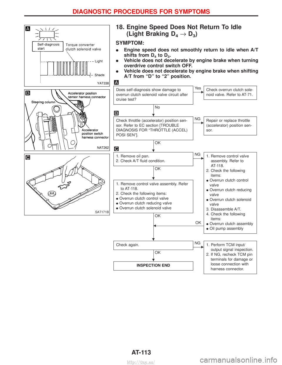
18. Engine Speed Does Not Return To Idle(Light Braking D
4®D3)
SYMPTOM:
I Engine speed does not smoothly return to idle when A/T
shifts from D
4to D3.
I Vehicle does not decelerate by engine brake when turning
overdrive control switch OFF.
I Vehicle does not decelerate by engine brake when shifting
A/T from ªDº to ª2º position.
Does self-diagnosis show damage to
overrun clutch solenoid valve circuit after
cruise test?
No
EYe s
Check overrun clutch sole-
noid valve. Refer to AT-71.
Check throttle (accelerator) position sen-
sor. Refer to EC section [TROUBLE
DIAGNOSIS FOR ªTHROTTLE (ACCEL)
POSI SENº].
OK
ENGRepair or replace throttle
(accelerator) position sen-
sor.
1. Remove oil pan.
2. Check A/T fluid condition.
OK
ENG 1. Remove control valve
assembly. Refer to
AT-118.
2. Check the following items:
I Overrun clutch control
valve
I Overrun clutch reducing
valve
I Overrun clutch solenoid
valve
3. Disassemble A/T.
4. Check the following items:
I Overrun clutch assembly
I Oil pump assembly
1. Remove control valve assembly. Refer
to AT-118.
2. Check the following items:
I Overrun clutch control valve
I Overrun clutch reducing valve
I Overrun clutch solenoid valve
OK
FOK
Check again.
OK
ENG 1. Perform TCM input/
output signal inspection.
2. If NG, recheck TCM pin terminals for damage or
loose connection with
harness connector.
INSPECTION END
YAT338
NAT262
SAT171B
H
H
H
HH
H
DIAGNOSTIC PROCEDURES FOR SYMPTOMS
AT-113
http://vnx.su/
Page 928 of 1833
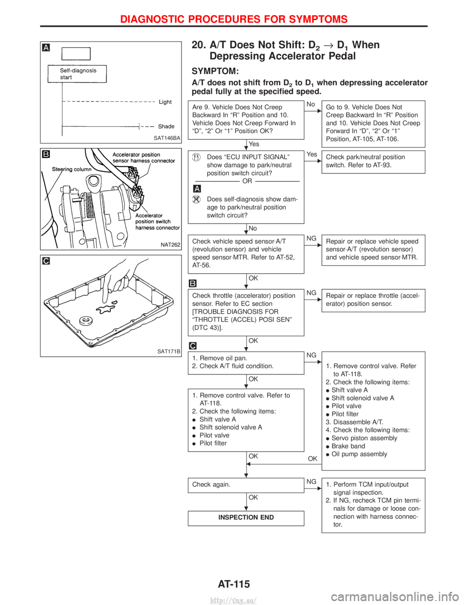
20. A/T Does Not Shift: D2®D1When
Depressing Accelerator Pedal
SYMPTOM:
A/T does not shift from D2to D1when depressing accelerator
pedal fully at the specified speed.
Are 9. Vehicle Does Not Creep
Backward In ªRº Position and 10.
Vehicle Does Not Creep Forward In
ªDº, ª2º Or ª1º Position OK?
Ye s
ENo Go to 9. Vehicle Does Not
Creep Backward In ªRº Position
and 10. Vehicle Does Not Creep
Forward In ªDº, ª2º Or ª1º
Position, AT-105, AT-106.
Does ªECU INPUT SIGNALº
show damage to park/neutral
position switch circuit?
---------------------------------------------------------------------------------------------------- -OR -----------------------------------------------------------------------------------------------------
Does self-diagnosis show dam-
age to park/neutral position
switch circuit?
No
EYe s
Check park/neutral position
switch. Refer to AT-93.
Check vehicle speed sensor×A/T
(revolution sensor) and vehicle
speed sensor×MTR. Refer to AT-52,
AT-56.
OK
ENGRepair or replace vehicle speed
sensor×A/T (revolution sensor)
and vehicle speed sensor×MTR.
Check throttle (accelerator) position
sensor. Refer to EC section
[TROUBLE DIAGNOSIS FOR
ªTHROTTLE (ACCEL) POSI SENº
(DTC 43)].
OK
ENGRepair or replace throttle (accel-
erator) position sensor.
1. Remove oil pan.
2. Check A/T fluid condition.
OK
ENG
1. Remove control valve. Referto AT-118.
2. Check the following items:
I Shift valve A
I Shift solenoid valve A
I Pilot valve
I Pilot filter
3. Disassemble A/T.
4. Check the following items:
I Servo piston assembly
I Brake band
I Oil pump assembly
1. Remove control valve. Refer to
AT-118.
2. Check the following items:
I Shift valve A
I Shift solenoid valve A
I Pilot valve
I Pilot filter
OKFOK
Check again.
OK
ENG 1. Perform TCM input/output
signal inspection.
2. If NG, recheck TCM pin termi- nals for damage or loose con-
nection with harness connec-
tor.
INSPECTION END
SAT146BA
NAT262
SAT171B
H
H
H
H
H
H
H
DIAGNOSTIC PROCEDURES FOR SYMPTOMS
AT-115
http://vnx.su/
Page 1041 of 1833
Installation
Install a new oil seal, using a suitable tool.
Rear Case
REAR OIL SEAL
Removal
Remove the oil seal. Be careful not to damage its housing. Always
replace after every disassembly.
Installation
Install a new oil seal, using the Special Tool.
AIR BREATHER
Install as shown in the illustration.
Shift Control Components
INSPECTION
ICheck contact surface and sliding surface for wear, scratches,
projections or other faulty conditions.
SMT315A
YMT025
YMT026
YTF005
SMT360A
REPAIR FOR COMPONENT PARTS
Bearing Retainer (Cont'd)
TF-24
http://vnx.su/
Page 1125 of 1833
Removal and Installation
ISet the auto-lock free-running hub at the condition ªFreeº.
I Remove auto-lock free-running hub with brake pedal
depressed.
I Remove snap ring.
I Remove washer B, washer A and brake B.
I After installing auto-lock free-running hub, check operation.
When installing it, apply recommended grease to drive shaft
end.
Inspection
Thoroughly clean parts and dry with compressed air.
Brake ªAº and ªBº
Measure the thickness ªLº of brake ªAº and ªBº.
If thickness is less than the specified limit, replace brake ªAº and
ªBº as a set. Wear limit ªLº = 15.4 mm (0.606 in)
YFA016
SFA827
SFA829
SFA548
FRONT AXLE Ð Auto-lock Free-running Hub
FA-14
http://vnx.su/
Page 1180 of 1833
5. Bleed the air from the rear brake piping.
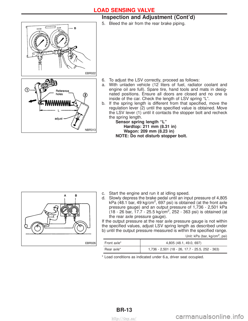
6. To adjust the LSV correctly, proceed as follows:
a. With unladen vehicle (12 liters of fuel, radiator coolant andengine oil are full). Spare tire, hand tools and mats in desig-
nated positions. Ensure all doors are closed and no one is
inside of the car. Check the length of LSV spring ªLº.
b. If the spring length is different from that specified, move the regulation lever (2) until the specified value is obtained. Move
the LSV lever (1) until it contacts the stopper bolt and recheck
the spring length.Sensor spring length ªLº Hardtop: 211 mm (8.31 in)
Wagon: 209 mm (8.23 in)
NOTE: Do not disturb stopper bolt.
c. Start the engine and run it at idling speed.
d. Slowly depress the brake pedal until an input pressure of 4,805 kPa (48.1 bar, 49 kg/cm
2, 697 psi) is obtained (at the front axle
pressure gauge) and an output pressure of 1,736 - 2,501 kPa
(18 - 26 bar, 17.7 - 25.5 kg/cm
2, 252 - 363 psi) is obtained (at
the rear axle pressure gauge).
If the output pressure at the rear axle pressure gauge is not within
the specified values, adjust LSV spring length as described under
b) until the output pressure measured is within the specified range.
Unit: kPa (bar, kg/cm2, psi)
Front axle* 4,805 (48.1, 49.0, 697)
Rear axle* 1,736 - 2,501 (18 - 26, 17.7 - 25.5, 252 - 363)
* Load conditions as indicated under 6.a, driver seat occupied.
EBR022
NBR313
EBR026
LOAD SENSING VALVE
Inspection and Adjustment (Cont'd)
BR-13
http://vnx.su/
Page 1184 of 1833
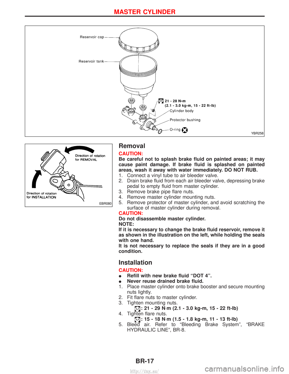
Removal
CAUTION:
Be careful not to splash brake fluid on painted areas; it may
cause paint damage. If brake fluid is splashed on painted
areas, wash it away with water immediately. DO NOT RUB.
1. Connect a vinyl tube to air bleeder valve.
2. Drain brake fluid from each air bleeder valve, depressing brakepedal to empty fluid from master cylinder.
3. Remove brake pipe flare nuts.
4. Remove master cylinder mounting nuts.
5. Remove protector of master cylinder, and avoid scratching the surface of master cylinder during removal.
CAUTION:
Do not disassemble master cylinder.
NOTE:
If it is necessary to change the brake fluid reservoir, remove it
as shown in the illustration on the left, while holding the seals
with one hand.
It is not necessary to replace the seals if they are in a good
condition.
Installation
CAUTION:
I Refill with new brake fluid ªDOT 4º.
I Never reuse drained brake fluid.
1. Place master cylinder onto brake booster and secure mounting nuts lightly.
2. Fit flare nuts to master cylinder.
3. Tighten mounting nuts.
:21-29N ×m (2.1 - 3.0 kg-m, 15 - 22 ft-lb)
4. Tighten flare nuts.
:15-18N ×m (1.5 - 1.8 kg-m, 11 - 13 ft-lb)
5. Bleed air. Refer to ªBleeding Brake Systemº, ªBRAKE HYDRAULIC LINEº, BR-8.
YBR258
EBR080
MASTER CYLINDER
BR-17
http://vnx.su/
Page 1189 of 1833
Inspection
HOSES AND CONNECTORS
ICheck condition of vacuum hoses and connectors.
I Check vacuum hoses and check valve for air tightness.
CHECK VALVE
ICheck vacuum with a manual vacuum pump.
Connect to booster
side Vacuum should exist.
Connect to engine
side Vacuum should not exist.
VACUUM WARNING SWITCH
Test continuity though vacuum warning switch with an ohmmeter
and vacuum pump.
VacuumLess than 26.7 kPa
(267 mbar, 200 mmHg, 7.87 inHg) 0W
33.3 kPa
(333 mbar, 250 mmHg, 9.84 inHg) or more
W
YBR447
YBR448
SBR007A
VACUUM HOSE
BR-22
http://vnx.su/