2004 NISSAN TERRANO air condition
[x] Cancel search: air conditionPage 741 of 1833
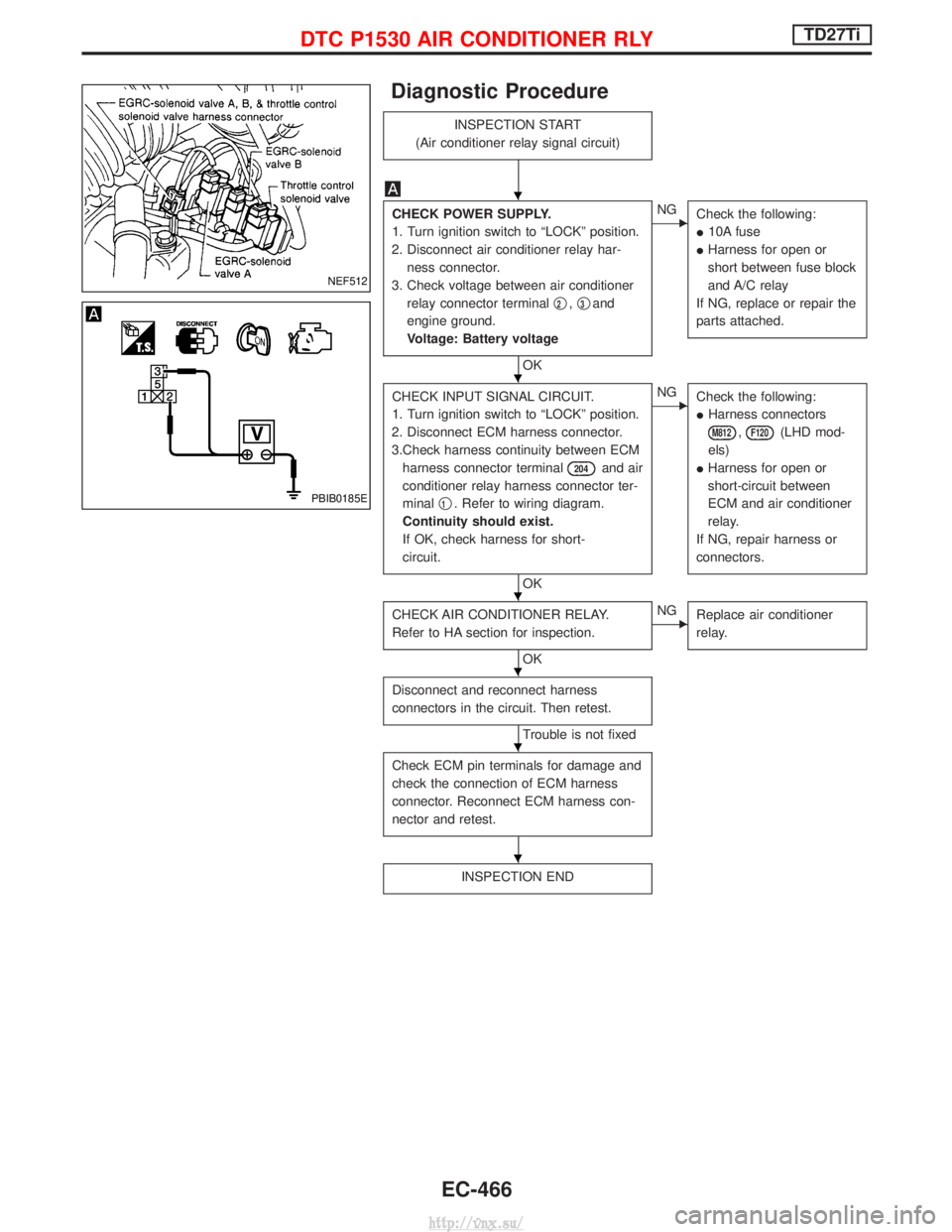
Diagnostic Procedure
INSPECTION START
(Air conditioner relay signal circuit)
CHECK POWER SUPPLY.
1. Turn ignition switch to ªLOCKº position.
2. Disconnect air conditioner relay har- ness connector.
3. Check voltage between air conditioner relay connector terminal q
2,q3and
engine ground.
Voltage: Battery voltage
OK
ENG Check the following:
I10A fuse
I Harness for open or
short between fuse block
and A/C relay
If NG, replace or repair the
parts attached.
CHECK INPUT SIGNAL CIRCUIT.
1. Turn ignition switch to ªLOCKº position.
2. Disconnect ECM harness connector.
3.Check harness continuity between ECM harness connector terminal
204and air
conditioner relay harness connector ter-
minal q
1. Refer to wiring diagram.
Continuity should exist.
If OK, check harness for short-
circuit.
OK
ENG Check the following:
IHarness connectors
M812,F120(LHD mod-
els)
I Harness for open or
short-circuit between
ECM and air conditioner
relay.
If NG, repair harness or
connectors.
CHECK AIR CONDITIONER RELAY.
Refer to HA section for inspection.
OK
ENG Replace air conditioner
relay.
Disconnect and reconnect harness
connectors in the circuit. Then retest.
Trouble is not fixed
Check ECM pin terminals for damage and
check the connection of ECM harness
connector. Reconnect ECM harness con-
nector and retest.
INSPECTION END
NEF512
PBIB0185E
H
H
H
H
H
H
DTC P1530 AIR CONDITIONER RLYTD27Ti
EC-466
http://vnx.su/
Page 748 of 1833
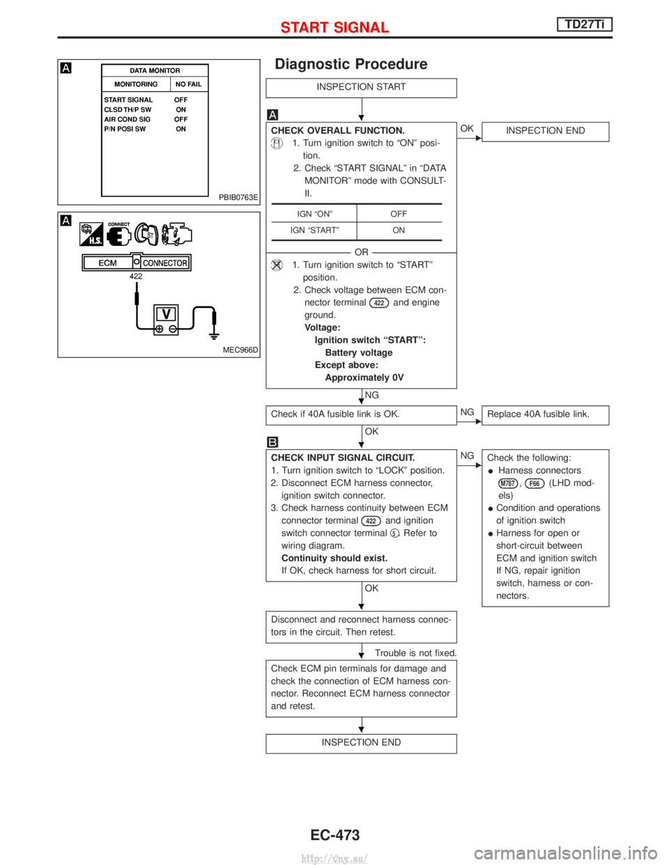
Diagnostic Procedure
INSPECTION START
CHECK OVERALL FUNCTION.
1. Turn ignition switch to ªONº posi-tion.
2. Check ªSTART SIGNALº in ªDATA MONITORº mode with CONSULT-
II.
------------------------------------------------------------------------------------------------------------------------------------- -OR--------------------------------------------------------------------------------------------------------------------------------------
1. Turn ignition switch to ªSTARTº
position.
2. Check voltage between ECM con- nector terminal
422and engine
ground.
Voltage: Ignition switch ªSTARTº:Battery voltage
Except above: Approximately 0V
NG
EOK INSPECTION END
Check if 40A fusible link is OK.
OKENGReplace 40A fusible link.
CHECK INPUT SIGNAL CIRCUIT.
1. Turn ignition switch to ªLOCKº position.
2. Disconnect ECM harness connector, ignition switch connector.
3. Check harness continuity between ECM connector terminal
422and ignition
switch connector terminal q
5. Refer to
wiring diagram.
Continuity should exist.
If OK, check harness for short circuit.
OK
ENG Check the following:
I Harness connectors
M787,F66(LHD mod-
els)
I Condition and operations
of ignition switch
I Harness for open or
short-circuit between
ECM and ignition switch
If NG, repair ignition
switch, harness or con-
nectors.
Disconnect and reconnect harness connec-
tors in the circuit. Then retest.
Trouble is not fixed.
Check ECM pin terminals for damage and
check the connection of ECM harness con-
nector. Reconnect ECM harness connector
and retest.
INSPECTION END
IGN ªONº OFF
IGN ªSTARTº ON
PBIB0763E
MEC966D
H
H
H
H
H
H
START SIGNALTD27Ti
EC-473
http://vnx.su/
Page 751 of 1833

General Specifications
Engine speed
Unit: rpm
EngineTD27Ti
Idle speed A/C: ON 725
845
Maximum engine speed 5,500
Pump numbers
Engine Part numberPump assembly num-
ber
TD27Ti 16700 7F406 A 460 801 135
Pump data is not yet available.
Refer to CALIBRATION STANDARD published
by BOSCH.
Injection Nozzle
INSPECTION AND ADJUSTMENT
Injection nozzle assembly
Unit: kPa (bar, kg/cm2, psi)
Initial injection pressure
New 12,749 - 13,730 (127.5 - 137.3, 130 - 140,
1,849 - 1,991)
Used 12,259 - 12,749 (122.6 - 127.5, 120 - 135,
1,706 - 1,849)
Inspection and Adjustment
Plunger lift mm (in)
at TDC 0.275 0.02
(0.0108) (0.0008)
Idle speed rpm
(ªNº or ªPº position) 725 25
MASS AIR FLOW SENSOR
Supply voltage
V Approximately 5
Output voltage V1.5 - 2.7*
*: Engine is warmed up sufficiently and idling under no-load.
ENGINE COOLANT TEMPERATURE
SENSOR
Temperature ÉC (ÉF) Resistance kW
20 (68) 2.1 - 2.9
50 (122) 0.68 - 1.00
90 (194) 0.236 - 0.260
CONTROL SLEEVE POSITION SENSOR
Resistance [at 25ÉC (77ÉF)] WApproximately 6.1
INJECTION TIMING CONTROL VALVE
Resistance [at 25ÉC (77ÉF)] WApproximately 15
NEEDLE LIFT SENSOR
Resistance [at 25ÉC (77ÉF)] WApproximately 105
CRANKSHAFT POSITION SENSOR (TDC)
Resistance [at 25ÉC (77ÉF)] WApproximately 900
GLOW PLUG
Resistance [at 25ÉC (77ÉF)] W0.5
ACCELERATOR POSITION SENSOR
Throttle valve conditions Resistance kW
[at 25ÉC (77ÉF)]
Completely closed Approximately 1.2
Partially open 1.2 - 1.9
Completely open Approximately 1.9
FUEL TEMPERATURE SENSOR
Temperature ÉC (ÉF)Resistance kW
25 (77) Approximately 1.9
SERVICE DATA AND SPECIFICATIONS (SDS)TD27Ti
EC-476
http://vnx.su/
Page 815 of 1833
Park/neutral Position, Overdrive Control or
Throttle (Accelerator) Position Switches ...................93
DIAGNOSTIC PROCEDURES FOR SYMPTOMS ........99
1. SPORT Indicator Lamp Does Not Come On ........99
2. SPORT or SNOW Indicator Lamp Does Not Come On.................................................................100
3. O/D OFF Indicator Lamp Does Not Come On....100
4. SPORT Indicator Lamp Does Not Come On ......101
5. Engine Cannot Be Started In ²P² and ²N²
Position....................................................................102
6. In ²P² Position, Vehicle Moves Forward Or
Backward When Pushed.........................................102
7. In ²N² Position, Vehicle Moves ...........................103
8. Large Shock. ²N² ->²R² Position .......................104
9. Vehicle Does Not Creep Backward In ²R²
Position....................................................................105
10. Vehicle Does Not Creep Forward In ²D² ,²2²
Or ²1² Position.........................................................106
11. Vehicle Cannot Be Started From D
1.................107
12. A/T Does Not Shift: D
1-> D2Or Does Not
Kickdown: D
4-> D2..................................................108
13. A/T Does Not Shift: D
2-> D3............................109
14. A/T Does Not Shift: D
3-> D4............................. 110
15. A/T Does Not Perform Lock-up ......................... 111
16. A/T Does Not Hold Lock-up Condition .............. 112
17. Lock-up Is Not Released ................................... 112
18. Engine Speed Does Not Return To Idle (Light Braking D
4-> D3)..................................................... 113
19. Vehicle Does Not Start From D
1....................... 114
20. A/T Does Not Shift: D
2-> D1When
Depressing Accelerator Pedal................................. 115
21. A/T Does Not Shift: D
4-> D3, When
Overdrive Control Switch ²ON² ->²OFF² ............... 116
22. A/T Does Not Shift: D
3-> 22, When Selector
Lever ²D² ->²2² Position......................................... 116
23. A/T Does Not Shift: 2
2-> 11, When Selector
Lever ²2² ->²1² Position ......................................... 117
24. Vehicle Does Not Decelerate By Engine
Brake........................................................................\
117 ON-VEHICLE SERVICE
.............................................. 118
Control Valve Assembly and Accumulators ............. 118
Revolution Sensor Replacement ............................. 119
Rear Oil Seal Replacement ..................................... 119
Parking Components Inspection.............................. 119
Park/neutral Position Switch Adjustment ................. 119
Manual Control Linkage Adjustment........................120
REMOVAL AND INSTALLATION ................................121
Removal ...................................................................121
Installation ................................................................122
MAJOR OVERHAUL ...................................................124
Oil Channel ..............................................................126
Locations of Needle Bearings, Thrust Washers
and Snap Rings .......................................................127
DISASSEMBLY ............................................................128
Disassembly.............................................................128
REPAIR FOR COMPONENT PARTS ..........................139
Oil Pump ..................................................................139
Control Valve Assembly ...........................................143
Control Valve Upper Body .......................................149
Control Valve Lower Body .......................................154
Reverse Clutch ........................................................156
High Clutch ..............................................................160
Forward and Overrun Clutches ...............................162
Low & Reverse Brake..............................................166
Forward Clutch Drum Assembly ..............................170
Rear Internal Gear and Forward Clutch Hub ..........173
Band Servo Piston Assembly ..................................176
Parking Pawl Components ......................................180
ASSEMBLY ..................................................................182
Assembly (1) ............................................................182
Adjustment ...............................................................190
Assembly (2) ............................................................193
A/T FLUID COOLER SYSTEM ...................................200
A/T Fluid Cooler.......................................................200
SERVICE DATA AND SPECIFICATIONS (SDS) ........201
General Specifications .............................................201
Specifications and Adjustment.................................201
When you read wiring diagrams:
I Read GI section, ªHOW TO READ WIRING DIAGRAMSº.
I See EL section, ªPOWER SUPPLY ROUTINGº for power distribution circuit.
When you perform trouble diagnoses, read GI section, ªHOW TO FOLLOW FLOW CHART IN
TROUBLE DIAGNOSESº and ªHOW TO PERFORM EFFICIENT DIAGNOSIS FOR AN ELECTRI-
CAL INCIDENTº.
CONTENTS(Cont'd)
AT- 2
http://vnx.su/
Page 839 of 1833
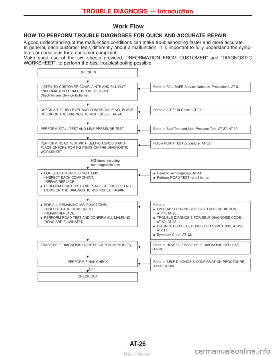
Work Flow
HOW TO PERFORM TROUBLE DIAGNOSES FOR QUICK AND ACCURATE REPAIR
A good understanding of the malfunction conditions can make troubleshooting faster and more accurate.
In general, each customer feels differently about a malfunction. It is important to fully understand the symp-
toms or conditions for a customer complaint.
Make good use of the two sheets provided, ªINFORMATION FROM CUSTOMERº and ªDIAGNOSTIC
WORKSHEETº, to perform the best troubleshooting possible.
CHECK IN
LISTEN TO CUSTOMER COMPLAINTS AND FILL OUT
ªINFORMATION FROM CUSTOMERº, AT-23.
Check for any Service Bulletins.FRefer to FAIL-SAFE Service Notice or Precautions, AT-5.
CHECK A/T FLUID LEVEL AND CONDITION. IF NG, PLACE
CHECK ON THE DIAGNOSTIC WORKSHEET, AT-24.FRefer to A/T Fluid Check, AT-27.
PERFORM STALL TEST AND LINE PRESSURE TEST.FRefer to Stall Test and Line Pressure Test, AT-27, AT-30.
PERFORM ROAD TEST WITH SELF-DIAGNOSIS AND
PLACE CHECKS FOR NG ITEMS ON THE DIAGNOSTIC
WORKSHEET.
NG items including
self-diagnostic item
FFollow ROAD TEST procedure, AT-32.
IFOR SELF-DIAGNOSIS NG ITEMS:
-INSPECT EACH COMPONENT.
-REPAIR/REPLACE.
I PERFORM ROAD TEST AND PLACE CHECKS FOR NG
ITEMS ON THE DIAGNOSTIC WORKSHEET AGAIN.FIRefer to self-diagnosis, AT-14.
I Perform ROAD TEST for all items.
IFOR ALL REMAINING MALFUNCTIONS:
-INSPECT EACH COMPONENT.
-REPAIR/REPLACE.
I PERFORM ROAD TEST AND CONFIRM ALL MALFUNC-
TIONS ARE ELIMINATED.FRefer to
ION BOARD DIAGNOSTIC SYSTEM DESCRIPTION,
AT-14, AT-20.
I TROUBLE DIAGNOSIS FOR SELF-DIAGNOSIS CODE,
AT-52, AT-93.
I DIAGNOSTIC PROCEDURES FOR SYMPTOMS, AT-26,
AT-117.
I Symptom Chart, AT-43.
ERASE SELF-DIAGNOSIS CODE FROM TCM MEMORIES.FRefer to HOW TO ERASE SELF-DIAGNOSIS RESULTS,
AT-19.
PERFORM FINAL CHECK
OK
FRefer to SELF-DIAGNOSIS CONFIRMATION PROCEDURE,
AT-52 - AT-86.
CHECK OUT
H
H
H
H
H
H
H
H
H
TROUBLE DIAGNOSIS Ð Introduction
AT-26
http://vnx.su/
Page 865 of 1833
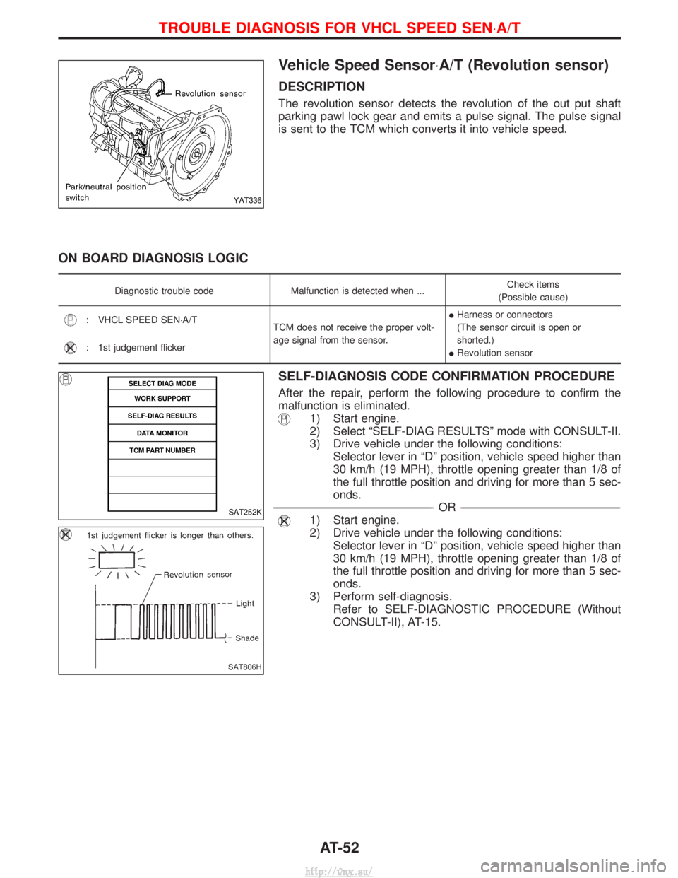
Vehicle Speed Sensor×A/T (Revolution sensor)
DESCRIPTION
The revolution sensor detects the revolution of the out put shaft
parking pawl lock gear and emits a pulse signal. The pulse signal
is sent to the TCM which converts it into vehicle speed.
ON BOARD DIAGNOSIS LOGIC
Diagnostic trouble codeMalfunction is detected when ... Check items
(Possible cause)
: VHCL SPEED SEN×A/T TCM does not receive the proper volt-
age signal from the sensor.I
Harness or connectors
(The sensor circuit is open or
shorted.)
I Revolution sensor
: 1st judgement flicker
SELF-DIAGNOSIS CODE CONFIRMATION PROCEDURE
After the repair, perform the following procedure to confirm the
malfunction is eliminated.
1) Start engine.
2) Select ªSELF-DIAG RESULTSº mode with CONSULT-II.
3) Drive vehicle under the following conditions:
Selector lever in ªDº position, vehicle speed higher than
30 km/h (19 MPH), throttle opening greater than 1/8 of
the full throttle position and driving for more than 5 sec-
onds.
----------------------------------------------------------------------------------------------------------------------------------------------------------------------------------------------------------------------------------------------------------- -OR------------------------------------------------------------------------------------------------------------------------------------------------------------------------------------------------------------------------------------------------------------
1) Start engine.
2) Drive vehicle under the following conditions:
Selector lever in ªDº position, vehicle speed higher than
30 km/h (19 MPH), throttle opening greater than 1/8 of
the full throttle position and driving for more than 5 sec-
onds.
3) Perform self-diagnosis. Refer to SELF-DIAGNOSTIC PROCEDURE (Without
CONSULT-II), AT-15.
YAT336
SAT252K
SAT806H
TROUBLE DIAGNOSIS FOR VHCL SPEED SEN ×A/T
AT-52
http://vnx.su/
Page 869 of 1833
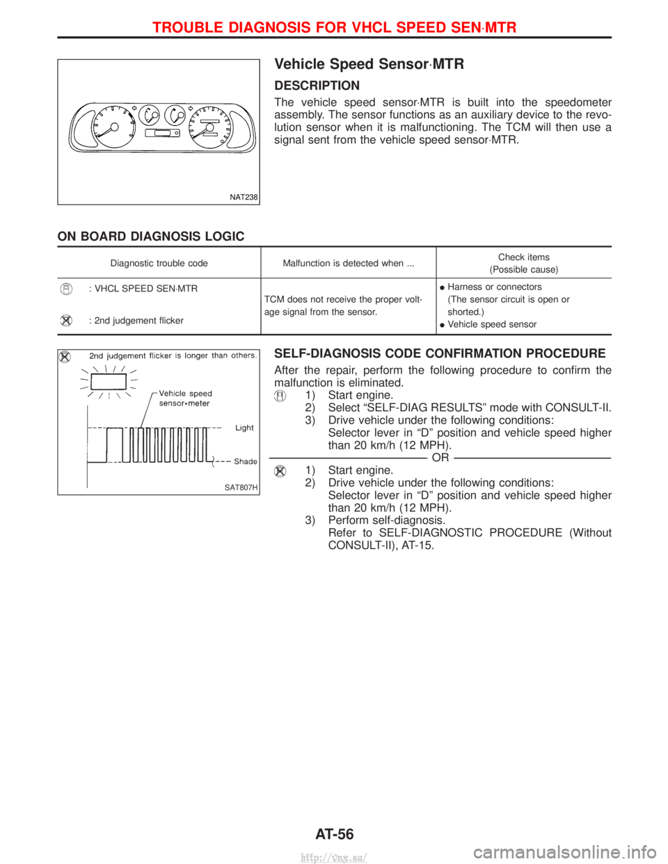
Vehicle Speed Sensor×MTR
DESCRIPTION
The vehicle speed sensor×MTR is built into the speedometer
assembly. The sensor functions as an auxiliary device to the revo-
lution sensor when it is malfunctioning. The TCM will then use a
signal sent from the vehicle speed sensor×MTR.
ON BOARD DIAGNOSIS LOGIC
Diagnostic trouble codeMalfunction is detected when ... Check items
(Possible cause)
: VHCL SPEED SEN×MTR TCM does not receive the proper volt-
age signal from the sensor.I
Harness or connectors
(The sensor circuit is open or
shorted.)
I Vehicle speed sensor
: 2nd judgement flicker
SELF-DIAGNOSIS CODE CONFIRMATION PROCEDURE
After the repair, perform the following procedure to confirm the
malfunction is eliminated.
1) Start engine.
2) Select ªSELF-DIAG RESULTSº mode with CONSULT-II.
3) Drive vehicle under the following conditions:
Selector lever in ªDº position and vehicle speed higher
than 20 km/h (12 MPH).
----------------------------------------------------------------------------------------------------------------------------------------------------------------------------------------------------------------------------------------------------------- -OR------------------------------------------------------------------------------------------------------------------------------------------------------------------------------------------------------------------------------------------------------------
1) Start engine.
2) Drive vehicle under the following conditions:
Selector lever in ªDº position and vehicle speed higher
than 20 km/h (12 MPH).
3) Perform self-diagnosis. Refer to SELF-DIAGNOSTIC PROCEDURE (Without
CONSULT-II), AT-15.
NAT238
SAT807H
TROUBLE DIAGNOSIS FOR VHCL SPEED SEN ×MTR
AT-56
http://vnx.su/
Page 875 of 1833

Throttle (Accelerator) Position Sensor
DESCRIPTION
The throttle (accelerator) position sensor detects the throttle valve
position and sends a signal to the TCM.
ON BOARD DIAGNOSIS LOGIC
Diagnostic trouble codeMalfunction is detected when ... Check items
(Possible cause)
: THROTTLE POSI SEN TCM receives an excessively low or
high voltage from the sensor.I
Harness or connectors
(The sensor circuit is open or
shorted.)
I Throttle (accelerator) position sensor
: 3rd judgement flicker
CONSULT-II REFERENCE VALUE IN DATA MONITOR MODE
Remarks: Specification data are reference values.
Monitor item ConditionSpecification
Throttle (accelerator) position sensor Fully-closed throttle
Approximately 0.5V
Fully-open throttle Approximately 4V
SELF-DIAGNOSIS CODE CONFIRMATION PROCEDURE
After the repair, perform the following procedure to confirm the
malfunction is eliminated.
1) Start engine.
2) Select ªSELF-DIAG RESULTSº mode with CONSULT-II.
3) Drive vehicle under the following conditions:
Selector lever in ªDº position, vehicle speed higher than
10 km/h (6 MPH), throttle opening greater than 1/2 of the
full throttle position and driving for more than 3 seconds.
----------------------------------------------------------------------------------------------------------------------------------------------------------------------------------------------------------------------------------------------------------- -OR------------------------------------------------------------------------------------------------------------------------------------------------------------------------------------------------------------------------------------------------------------
1) Start engine.
2) Drive vehicle under the following conditions:
Selector lever in ªDº position, vehicle speed higher than
10 km/h (6 MPH), throttle opening greater than 1/2 of the
full throttle position and driving for more than 3 seconds.
3) Perform self-diagnosis. Refer to SELF-DIAGNOSTIC PROCEDURE (Without
CONSULT-II), AT-15.
NAT262
SAT808H
TROUBLE DIAGNOSIS FOR THROTTLE POSI SEN
AT-62
http://vnx.su/