Page 2381 of 3870
Fig. 281: Removing And Installing Heater Uni
t
Courtesy of MITSUBISHI MOTOR SALES OF AMERICA.
REMOVAL SERVICE POINTS << A >> SUCTION PIPE AND LIQUID PIPE DISCONNECTION To prevent the entry of dust or other foreign bodies, plug the dismantled hose and
the nipples of the expansion valves. Fig. 282: Identifying Connectors
Courtesy of MITSUBISHI MOTOR SALES OF AMERICA.CAUTION: As the compressor oil and receiver are highly
moisture absorbent, use a non-porous material to
plug the hose and nipples.
2004 Mitsubishi Endeavor LS
2004 HVAC Heater Air Conditioning, Ventilation - Endeavor
Page 2397 of 3870
Measure the resistance between the sensor terminals under at least two
temperatures. The resistance values should meet the values shown. Fig. 295: Temperature Resistance Graph
Courtesy of MITSUBISHI MOTOR SALES OF AMERICA.
COMPRESSOR ASSEMBLY AND TENSION PULLEY REMOVAL AND INSTALLATION NOTE: The temperature should be within the shown range.
2004 Mitsubishi Endeavor LS
2004 HVAC Heater Air Conditioning, Ventilation - Endeavor
Page 2398 of 3870
Fig. 296: Pre Removal And Post Installation Operation Chart
Courtesy of MITSUBISHI MOTOR SALES OF AMERICA.
Fig. 297: Removing And Installing Compressor Assembly
Courtesy of MITSUBISHI MOTOR SALES OF AMERICA.
REMOVAL SERVICE POINTS << A >> FLEXIBLE SUCTION HOSE AND FLEXIBLE DISCHARGE HOSE DISCONNECTION
2004 Mitsubishi Endeavor LS
2004 HVAC Heater Air Conditioning, Ventilation - Endeavor
Page 2399 of 3870

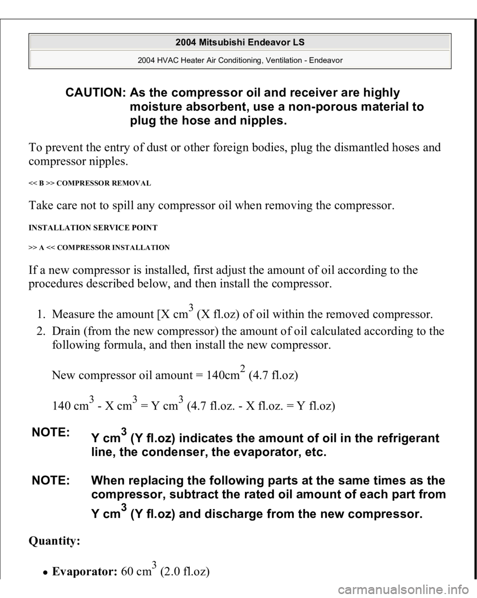
To prevent the entry of dust or other foreign bodies, plug the dismantled hoses and
compressor nipples. << B >> COMPRESSOR REMOVAL Take care not to spill any compressor oil when removing the compressor. INSTALLATION SERVICE POINT >> A << COMPRESSOR INSTALLATION If a new compressor is installed, first adjust the amount of oil according to the
procedures described below, and then install the compressor.
1. Measure the amount [X cm
3 (X fl.oz) of oil within the removed compressor.
2. Drain (from the new compressor) the amount of oil calculated according to the
following formula, and then install the new compressor.
New compressor oil amount = 140cm
2 (4.7 fl.oz)
140 cm
3 - X cm
3 = Y cm
3 (4.7 fl.oz. - X fl.oz. = Y fl.oz)
Quantity:
Eva
porator
: 60 c
m3 (2.0 fl.oz
)
CAUTION: As the compressor oil and receiver are highly
moisture absorbent, use a non-porous material to
plug the hose and nipples.
NOTE:
Y cm
3 (Y fl.oz) indicates the amount of oil in the refrigerant
line, the condenser, the evaporator, etc.
NOTE: When replacing the following parts at the same times as the
compressor, subtract the rated oil amount of each part from
Y cm3 (Y fl.oz) and discharge from the new compressor.
2004 Mitsubishi Endeavor LS
2004 HVAC Heater Air Conditioning, Ventilation - Endeavor
Page 2400 of 3870
Condenser:
15 cm
3 (0.5 fl.oz)
Suction hose:
10 cm
3 (0.3 fl.oz)
Receiver:
10 cm
3 (0.3 fl.oz)
INSPECTION COMPRESSOR AIR CONDITIONING COMPRESSOR CLUTCH OPERATION CHECK Connect the compressor connector terminal to the battery positive (+) terminal and
ground the battery's negative (-) terminal to the compressor unit. At that time, the
air conditioning compressor clutch should make a definite operating sound. Fig. 298: Checking A/C Compressor Clutch
Courtesy of MITSUBISHI MOTOR SALES OF AMERICA.
DISASSEMBLY AND ASSEMBLY
2004 Mitsubishi Endeavor LS
2004 HVAC Heater Air Conditioning, Ventilation - Endeavor
Page 2401 of 3870
Fig. 299: Exploded View Of A/C Compressor Components
Courtesy of MITSUBISHI MOTOR SALES OF AMERICA.
DISASSEMBLY SERVICE POINT << A >> SELF-LOCKING NUT REMOVAL
2004 Mitsubishi Endeavor LS
2004 HVAC Heater Air Conditioning, Ventilation - Endeavor
Page 2402 of 3870
Fig. 300: Removing Self
-Locking Nut
Courtesy of MITSUBISHI MOTOR SALES OF AMERICA.
ASSEMBLY SERVICE POINTS >> A << FIELD CORE ATTACHMENT Line up the pin hole on the compressor unit with the field core projection and
attach.
2004 Mitsubishi Endeavor LS
2004 HVAC Heater Air Conditioning, Ventilation - Endeavor
Page 2404 of 3870
Fig. 302: Identifying Snap Ring Tapered Part
Courtesy of MITSUBISHI MOTOR SALES OF AMERICA.
>> C << SELF-LOCKING NUT INSTALLATION Using a special tool, as when removing the nut, secure the armature and tighten the
self-locking nut. >> D << AIR GAP ADJUSTMENT Apply voltage from the battery to the air conditioning compressor clutch and check
that the clutch air gap is inside the standard value. If outside the standard value, use
a shim to adjust the gap. Standard value:
0.3 - 0.5 mm (0.012 - 0.020 inch)
2004 Mitsubishi Endeavor LS
2004 HVAC Heater Air Conditioning, Ventilation - Endeavor