Page 2871 of 3870
Fig. 31: Removing & Installing Steering Shaft
Courtesy of MITSUBISHI MOTOR SALES OF AMERICA.
REMOVAL SERVICE POINT << A>>STEERING COLUMN SHAFT ASSEMBLY REMOVAL
CAUTION: The tilt lever should be held in the lock position until
the steering column shaft is installed to the vehicle. If
the steering column is removed with the tilt lever
released, or the tilt lever is released after the steering
2004 Mitsubishi Endeavor LS
2004 STEERING Power Steering - Endeavor
Page 2875 of 3870

Courtesy of MITSUBISHI MOTOR SALES OF AMERICA
.
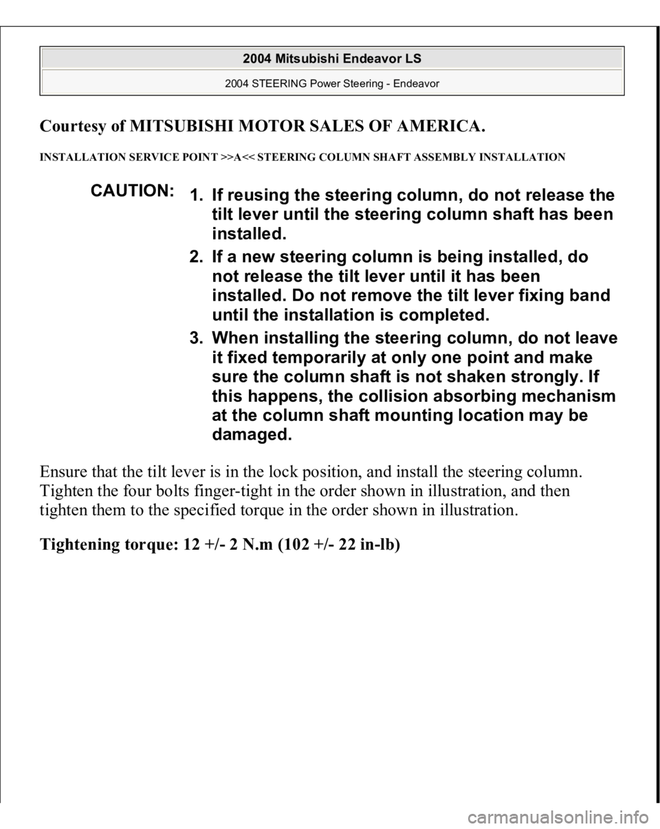
INSTALLATION SERVICE POINT >>A<< STEERING COLUMN SHAFT ASSEMBLY INSTALLATION Ensure that the tilt lever is in the lock position, and install the steering column.
Tighten the four bolts finger-tight in the order shown in illustration, and then
tighten them to the specified torque in the order shown in illustration.
Tightening torque: 12 +/- 2 N.m (102 +/- 22 in-lb)
CAUTION:
1. If reusin
g the steerin
g column, do not release the
tilt lever until the steering column shaft has been
installed.
2. If a new steering column is being installed, do
not release the tilt lever until it has been
installed. Do not remove the tilt lever fixing band
until the installation is completed.
3. When installing the steering column, do not leave
it fixed temporarily at only one point and make
sure the column shaft is not shaken strongly. If
this happens, the collision absorbing mechanism
at the column shaft mounting location may be
damaged.
2004 Mitsubishi Endeavor LS
2004 STEERING Power Steering - Endeavor
Page 2876 of 3870
Fig. 34: Checking Tilt Lever Position
Courtesy of MITSUBISHI MOTOR SALES OF AMERICA.
INSTALLATION SERVICE POINT >>B<< STEERING WHEEL SENSOR < VEHICLES WITH ASC>, CLOCK
SPRING AND COLUMN SWITCH ASSEMBLY INSTALLATION 1. Align the mating marks of the clock spring.
WARNING:Ensure that the clock spring's mating marks are
properly aligned. If not, the steering wheel may not
rotate completely during a turn, or the flat cable in
the clock spring could be damaged, This would
prevent normal SRS operation and possibly cause
serious injury to the driver.
2004 Mitsubishi Endeavor LS
2004 STEERING Power Steering - Endeavor
Page 2879 of 3870
Fig. 37: Disassembling Steering Shaft
Courtesy of MITSUBISHI MOTOR SALES OF AMERICA.
DISASSEMBLY SERVICE POINT << A>> SPECIAL BOLT REMOVAL 1. Drill in the special bolt a hole deep enough for the tap to stand.
2. Remove the special bolt with a lef
t-hand tap.
until the installation is completed. If you move it
accidentally, the steering column cannot be
reinstalled correctly.
2004 Mitsubishi Endeavor LS
2004 STEERING Power Steering - Endeavor
Page 2880 of 3870
Fig. 38: Removing Special Bolt With A Left
-Hand Tap
Courtesy of MITSUBISHI MOTOR SALES OF AMERICA.
ASSEMBLY SERVICE POINT >>A<< STEERING LOCK CYLINDER ASSEMBLY/SPECIAL BOLT
INSTALLATION 1. When installing the steering lock cylinder to the steering column assembly,
temporarily install the steering lock in alignment with the column boss.
2. After checking that the lock works properly, tighten the special bolts until the
head is twisted off.
CAUTION: The bolts must be replaced with new ones when the
steering lock is installed.
2004 Mitsubishi Endeavor LS
2004 STEERING Power Steering - Endeavor
Page 2884 of 3870
MB991897: Ball Joint Remover
REMOVAL SERVICE POINT << A>> TIE ROD END AND KNUCKLE DISCONNECTION 1. Install special tool MB991897 as shown in the figure.
Fig. 42: Installing Special Tool
Courtesy of MITSUBISHI MOTOR SALES OF AMERICA.
CAUTION:
Do not remove the nut from ball joint. Loosen it
and use special tool MB991897 to avoid possible
damage to ball joint threads. Hang special tool MB991897 with a cord to
prevent it from falling.
2004 Mitsubishi Endeavor LS
2004 STEERING Power Steering - Endeavor
Page 2885 of 3870
2. Turn the bolt and knob as necessary to make the jaws of special tool
MB991897 parallel, tighten the bolt by hand and confirm that the jaws are still
parallel.
3. Tighten the bolt with a wrench to disconnect the tie rod end.
Fig. 43: Turning Bolt And Knob
Courtesy of MITSUBISHI MOTOR SALES OF AMERICA.
REMOVAL SERVICE POINT << B>> FRONT AXLE CROSSMEMBER STAY REMOVAL The crossmember mounting bolts need not be unscrewed when the front axle
crossmember stay is replaced. However, the bolts may be loose while the front axle
NOTE: When adjusting the jaws in parallel, make sure the knob
is in the position shown in the figure.
2004 Mitsubishi Endeavor LS
2004 STEERING Power Steering - Endeavor
Page 2886 of 3870
crossmember stay is removed. Retighten the bolts to 180 +/- 20 N.m (13 +/- 14 ft-
lb).
Fig. 44: Removing Front Axle Crossmember Stay
Courtesy of MITSUBISHI MOTOR SALES OF AMERICA.
REMOVAL SERVICE POINT << C>> CROSSMEMBER ASSEMBLY REMOVAL 1. Use a transmission jack to hold the crossmember, and then remove the
crossmember mounting nuts and bolts.
2. Lower the crossmember with the rear roll stopper, the stabilizer bar, the return
tube, and the steerin
g gear.
2004 Mitsubishi Endeavor LS
2004 STEERING Power Steering - Endeavor