Page 2512 of 3870
Fig. 74: Removing And Installing Sensors
Courtesy of MITSUBISHI MOTOR SALES OF AMERICA.
INSPECTION INTERIOR TEMPERATURE SENSOR CHECK When the resistance between the sensor terminals is measured under two or more
temperature conditions, the resistance should approximately satisfy the illustrated
values.
2004 Mitsubishi Endeavor LS
2004 HVAC Automatic Air Conditioning - Endeavor
Page 2515 of 3870
PHOTO SENSOR CHEC
K
1. Connect the scan tool MB991958, and check the data list of the photo sensor.
2. Check that the displayed value changes when your cover the photo sensor with
your hands. OTHER PARTS OTHER PARTS MAINTENANCE SERVICE POINTS The followin
g maintenance service
points are the same as for the manual A/C.
NOTE: In the following illustration, for adjustment, check and test
information, refer to ON
-VEHICLE SERVICE
. For removal
and installation information, refer to appropriate
procedures in HEATER, AIR CONDITIONER AND
VENTILATION
.
2004 Mitsubishi Endeavor LS
2004 HVAC Automatic Air Conditioning - Endeavor
Page 2683 of 3870

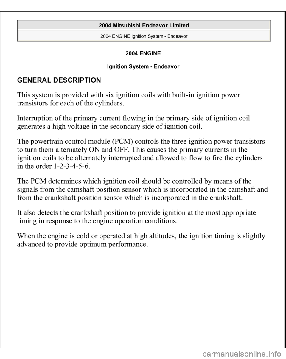
2004 ENGINE
Ignition System - Endeavor
GENERAL DESCRIPTION This system is provided with six ignition coils with built-in ignition power
transistors for each of the cylinders.
Interruption of the primary current flowing in the primary side of ignition coil
generates a high voltage in the secondary side of ignition coil.
The powertrain control module (PCM) controls the three ignition power transistors
to turn them alternately ON and OFF. This causes the primary currents in the
ignition coils to be alternately interrupted and allowed to flow to fire the cylinders
in the order 1-2-3-4-5-6.
The PCM determines which ignition coil should be controlled by means of the
signals from the camshaft position sensor which is incorporated in the camshaft and
from the crankshaft position sensor which is incorporated in the crankshaft.
It also detects the crankshaft position to provide ignition at the most appropriate
timing in response to the engine operation conditions.
When the engine is cold or operated at high altitudes, the ignition timing is slightly
advanced to
provide o
ptimum
performance.
2004 Mitsubishi Endeavor Limited 2004 ENGINE Ignition System - Endeavor
2004 Mitsubishi Endeavor Limited 2004 ENGINE Ignition System - Endeavor
Page 2684 of 3870
Fig. 1: Ignition System Circuit Diagram
Courtesy of MITSUBISHI MOTOR SALES OF AMERICA.
SPECIAL TOOLS Fig. 2: Identifying Special Tool
Courtesy of MITSUBISHI MOTOR SALES OF AMERICA.
ON-VEHICLE SERVICE KNOCK CONTROL SYSTEM CHECK Check the knock sensor circuit if diagnostic trouble code, No. P0325 is shown.
Refer to DTC P0325: KNOCK SENSOR CIRCUIT MALFUNCTION
.
2004 Mitsubishi Endeavor Limited 2004 ENGINE Ignition System - Endeavor
Page 2689 of 3870
Fig. 7: Locating Iridium Tip
Courtesy of MITSUBISHI MOTOR SALES OF AMERICA.
CAMSHAFT POSITION SENSOR CHECK Refer to DTC P0340: CAMSHAFT POSITION SENSOR CIRCUIT
.
CRANKSHAFT POSITION SENSOR CHECK Refer to DTC P0335: CRANKSHAFT POSITION SENSOR CIRCUIT
.
2004 Mitsubishi Endeavor Limited 2004 ENGINE Ignition System - Endeavor
Page 2690 of 3870
IGNITION COI
L
REMOVAL AND INSTALLATION Fig. 8: Removing And Installing Ignition Coil
Courtesy of MITSUBISHI MOTOR SALES OF AMERICA.
CAMSHAFT POSITION SENSOR REMOVAL AND INSTALLATION
2004 Mitsubishi Endeavor Limited 2004 ENGINE Ignition System - Endeavor
Page 2691 of 3870
Fig. 9: Removing And Installing Camshaft Position Sensor
Courtesy of MITSUBISHI MOTOR SALES OF AMERICA.
CRANKSHAFT POSITION SENSOR REMOVAL AND INSTALLATION Pre-removal and Post-installation Operation
Timin
g Belt Lower Cover Removal and Installation
(Refer to TIMING BELT
).
2004 Mitsubishi Endeavor Limited 2004 ENGINE Ignition System - Endeavor
Page 2692 of 3870
Fig. 10: Removing And Installing Crankshaft Position Sensor
Courtesy of MITSUBISHI MOTOR SALES OF AMERICA.
KNOCK SENSOR REMOVAL AND INSTALLATION Pre-removal and Post-installation Operation
Intake Manifold Removal and Installation (Refer to REMOVAL AND INSTALLATION
).
2004 Mitsubishi Endeavor Limited 2004 ENGINE Ignition System - Endeavor