Page 2855 of 3870
1. Raise and support the front wheels.
2. Disconnect the return hose connection, and then connect a vinyl hose to the
return hose, and drain the fluid into a container.
Fig. 23: Disconnecting Return Hose Connection
Courtesy of MITSUBISHI MOTOR SALES OF AMERICA.
3. Disconnect the ignition coil connectors (Refer to IGNITION COIL
).
4. While operating the starter motor intermittently, turn the steering wheel all the
way to the left and right several times to drain all of the fluid.
5. Connect the return hose securely, and then secure with the clip.
6. Fill the oil reservoir with GENUINE MITSUBISHI POWER STEERING
FLUID up to the lower mark of the reservoir, and then bleed the air.
POWER STEERING SYSTEM AIR BLEEDIN
G
2004 Mitsubishi Endeavor LS
2004 STEERING Power Steering - Endeavor
Page 2856 of 3870

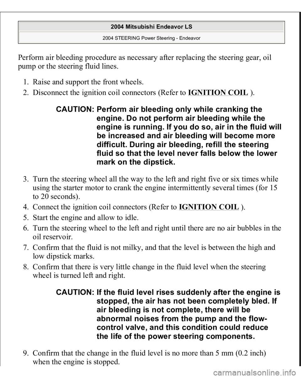
Perform air bleeding procedure as necessary after replacing the steering gear, oil
pump or the steering fluid lines.
1. Raise and support the front wheels.
2. Disconnect the ignition coil connectors (Refer to IGNITION COIL
).
3. Turn the steering wheel all the way to the left and right five or six times while
using the starter motor to crank the engine intermittently several times (for 15
to 20 seconds).
4. Connect the ignition coil connectors (Refer to IGNITION COIL
).
5. Start the engine and allow to idle.
6. Turn the steering wheel to the left and right until there are no air bubbles in the
oil reservoir.
7. Confirm that the fluid is not milky, and that the level is between the high and
low dipstick marks.
8. Confirm that there is very little change in the fluid level when the steering
wheel is turned left and right.
9. Confirm that the change in the fluid level is no more than 5 mm (0.2 inch)
when the en
gine is sto
pped.
CAUTION: Perform air bleeding only while cranking the
engine. Do not perform air bleeding while the
en
gine is runnin
g. If
you do so, air in the fluid will
be increased and air bleeding will become more
difficult. During air bleeding, refill the steering
fluid so that the level never falls below the lower
mark on the dipstick.
CAUTION: If the fluid level rises suddenly after the engine is
stopped, the air has not been completely bled. If
air bleeding is not complete, there will be
abnormal noises from the pump and the flow-
control valve, and this condition could reduce
the life of the power steering components.
2004 Mitsubishi Endeavor LS
2004 STEERING Power Steering - Endeavor
Page 3534 of 3870

2004 STARTING & CHARGING SYSTEMS
Starters - Endeavor
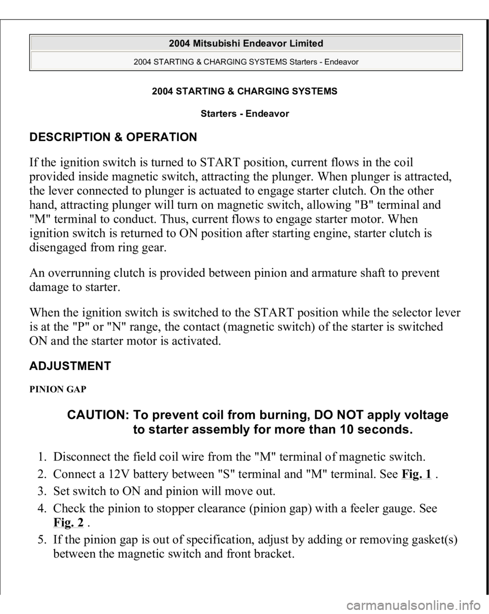
DESCRIPTION & OPERATION If the ignition switch is turned to START position, current flows in the coil
provided inside magnetic switch, attracting the plunger. When plunger is attracted,
the lever connected to plunger is actuated to engage starter clutch. On the other
hand, attracting plunger will turn on magnetic switch, allowing "B" terminal and
"M" terminal to conduct. Thus, current flows to engage starter motor. When
ignition switch is returned to ON position after starting engine, starter clutch is
disengaged from ring gear.
An overrunning clutch is provided between pinion and armature shaft to prevent
damage to starter.
When the ignition switch is switched to the START position while the selector leve
r
is at the "P" or "N" range, the contact (magnetic switch) of the starter is switched
ON and the starter motor is activated.
ADJUSTMENT PINION GAP 1. Disconnect the field coil wire from the "M" terminal of magnetic switch.
2. Connect a 12V battery between "S" terminal and "M" terminal. See Fig. 1
.
3. Set switch to ON and pinion will move out.
4. Check the pinion to stopper clearance (pinion gap) with a feeler gauge. See
Fig. 2
.
5. If the pinion gap is out of specification, adjust by adding or removing gasket(s)
between the ma
gnetic switch and front bracket. CAUTION: To prevent coil from burning, DO NOT apply voltage
to starter assembly for more than 10 seconds.
2004 Mitsubishi Endeavor Limited
2004 STARTING & CHARGING SYSTEMS Starters - Endeavor
2004 Mitsubishi Endeavor Limited
2004 STARTING & CHARGING SYSTEMS Starters - Endeavor
Page 3535 of 3870
Fig. 1: Adjusting Pinion Gap
Courtesy of MITSUBISHI MOTOR SALES OF AMERICA.
2004 Mitsubishi Endeavor Limited
2004 STARTING & CHARGING SYSTEMS Starters - Endeavor
Page 3536 of 3870
Fig. 2: Measuring Pinion Gap
Courtesy of MITSUBISHI MOTOR SALES OF AMERICA
TROUBLE SHOOTING STARTER MOTOR DOES NOT OPERATE
Check the starter (coil). Check for poor contact at the battery terminals and starter. Check the transmission ran
ge switch.
WARNING:Battery posts, terminals and related accessories
contain lead and lead compounds. Wash hands after
handling.
2004 Mitsubishi Endeavor Limited
2004 STARTING & CHARGING SYSTEMS Starters - Endeavor
Page 3537 of 3870

STARTER MOTOR DOES NOT STOPCheck the magnetic switch. ON-VEHICLE TESTING STARTER MOTOR DOES NOT OPERATE 1. Is the battery in good condition? If Yes, go to the next step. If No, then charge
or replace battery.
2. Disconnect the starter motor "S" (solenoid) terminal connector. Using a jumper
wire, apply battery positive voltage to starter motor "S" (solenoid) terminal.
Does starter motor operate normally? If Yes, then check ignition switch,
transmission range switch and the line between the battery and starter motor
"S" (solenoid) terminal. If No, then go to the next step.
3. Check if the cable between starter "B" (battery) terminal and battery positive
terminal for connection and continuity. Is the starter cable in good condition? I
f
Yes, then go to the next step. If No, then repair or replace the cable.
4. Check the connection and continuity of the cable between starter motor body
and the negative battery terminal. Is the ground line in good condition? If Yes,
then go to the next step. If No, then repair or replace cable.
5. Is the starter motor in good condition? If Yes, problem is excessive rotational
resistance of the engine. If No, then replace the starter motor.
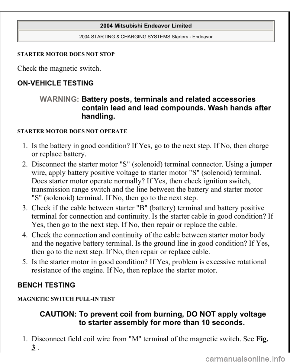
BENCH TESTING MAGNETIC SWITCH PULL-IN TEST 1. Disconnect field coil wire from "M" terminal of the magnetic switch. See Fig.
3 . WARNING:Battery posts, terminals and related accessories
contain lead and lead compounds. Wash hands after
handling.
CAUTION: To prevent coil from burning, DO NOT apply voltage
to starter assembly for more than 10 seconds.
2004 Mitsubishi Endeavor Limited
2004 STARTING & CHARGING SYSTEMS Starters - Endeavor
Page 3538 of 3870
2. Connect a 12-volt battery between "S" terminal and "M" terminal.
3. If the pinion moves out, the pull-in coil is good. If it doesn't, replace the
magnetic switch.
Fig. 3: Magnetic Switch Pull
-in Test
Courtesy of MITSUBISHI MOTOR SALES OF AMERICA.
MAGNETIC SWITCH HOLD IN TEST
CAUTION: To prevent coil from burning, DO NOT apply voltage
to starter assembly for more than 10 seconds.
2004 Mitsubishi Endeavor Limited
2004 STARTING & CHARGING SYSTEMS Starters - Endeavor
Page 3539 of 3870
1. Disconnect the field coil wire from "M" terminal of the magnetic switch. See
Fig. 4
.
2. Connect 12-volt battery between the "S" terminal and body.
3. Manually pull out the pinion as far as the pinion stopper position.
4. If the pinion remains out, everything is operating properly. If pinion moves in,
hold-in circuit is open. Replace the magnetic switch.
Fig. 4: Magnetic Switch Hold
-in Test
Courtesy of MITSUBISHI MOTOR SALES OF AMERICA.
MAGNETIC SWITCH RETURN TEST
2004 Mitsubishi Endeavor Limited
2004 STARTING & CHARGING SYSTEMS Starters - Endeavor