Page 2574 of 3870
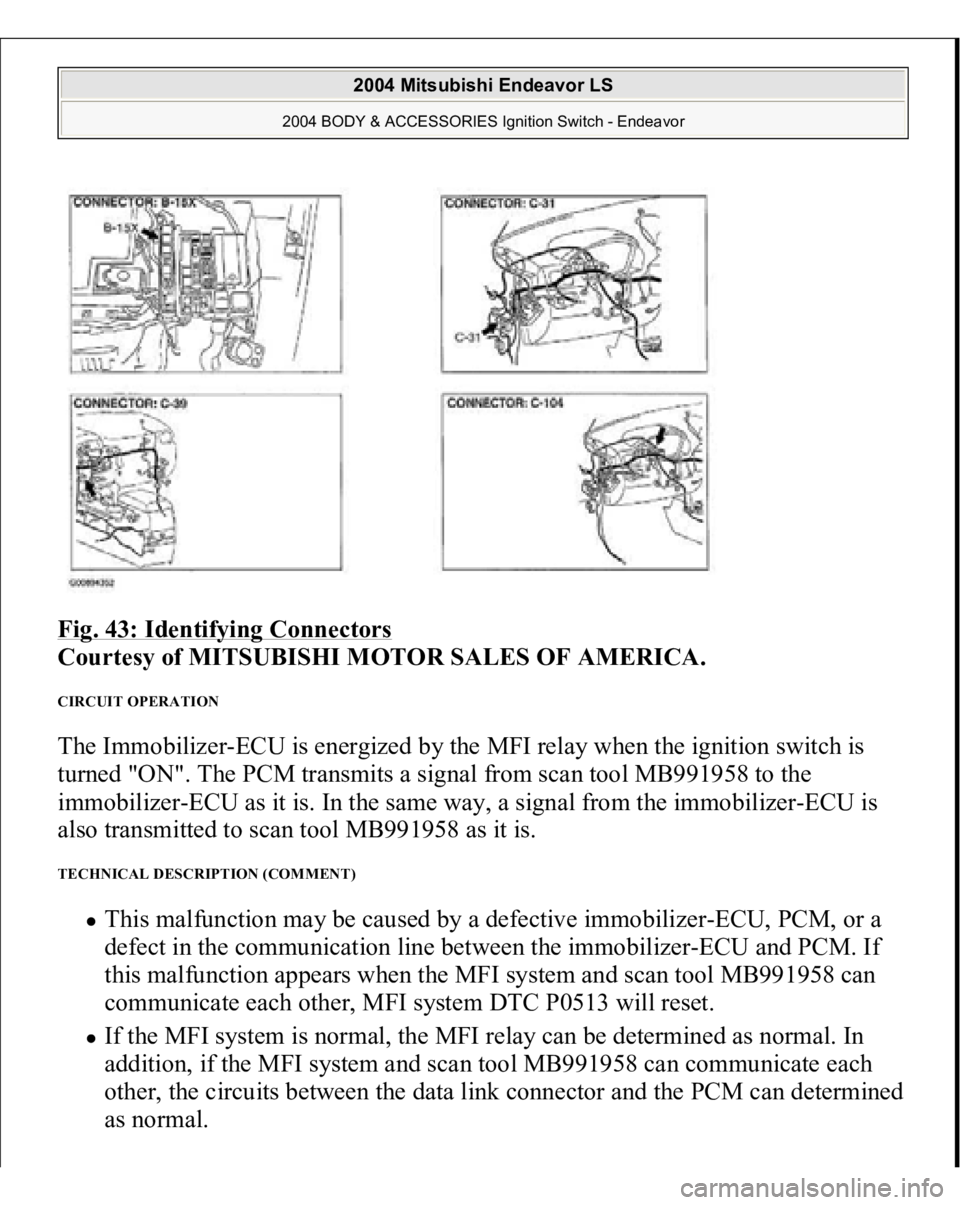
Fig. 43: Identifying Connectors
Courtesy of MITSUBISHI MOTOR SALES OF AMERICA.
CIRCUIT OPERATION The Immobilizer-ECU is energized by the MFI relay when the ignition switch is
turned "ON". The PCM transmits a signal from scan tool MB991958 to the
immobilizer-ECU as it is. In the same way, a signal from the immobilizer-ECU is
also transmitted to scan tool MB991958 as it is. TECHNICAL DESCRIPTION (COMMENT)
This malfunction may be caused by a defective immobilizer-ECU, PCM, or a
defect in the communication line between the immobilizer-ECU and PCM. If
this malfunction appears when the MFI system and scan tool MB991958 can
communicate each other, MFI system DTC P0513 will reset. If the MFI system is normal, the MFI relay can be determined as normal. In
addition, if the MFI system and scan tool MB991958 can communicate each
other, the circuits between the data link connector and the PCM can determined
as normal.
2004 Mitsubishi Endeavor LS
2004 BODY & ACCESSORIES Ignition Switch - Endeavor
Page 2683 of 3870
2004 ENGINE
Ignition System - Endeavor
GENERAL DESCRIPTION This system is provided with six ignition coils with built-in ignition power
transistors for each of the cylinders.
Interruption of the primary current flowing in the primary side of ignition coil
generates a high voltage in the secondary side of ignition coil.
The powertrain control module (PCM) controls the three ignition power transistors
to turn them alternately ON and OFF. This causes the primary currents in the
ignition coils to be alternately interrupted and allowed to flow to fire the cylinders
in the order 1-2-3-4-5-6.
The PCM determines which ignition coil should be controlled by means of the
signals from the camshaft position sensor which is incorporated in the camshaft and
from the crankshaft position sensor which is incorporated in the crankshaft.
It also detects the crankshaft position to provide ignition at the most appropriate
timing in response to the engine operation conditions.
When the engine is cold or operated at high altitudes, the ignition timing is slightly
advanced to
provide o
ptimum
performance.
2004 Mitsubishi Endeavor Limited 2004 ENGINE Ignition System - Endeavor
2004 Mitsubishi Endeavor Limited 2004 ENGINE Ignition System - Endeavor
Page 2726 of 3870
2004 BODY & ACCESSORIES
Keyless Entry System - Endeavor
GENERAL DESCRIPTION
Antenna and receiver are incorporated in the ETACS-ECU. ID code can be registered by using scan tool MB991958 (MUT-III sub
assembly). Transmitter is a key holder type, which incorporates lock button, unlock button
and panic button. When the transmitter unlock button is pressed once, the driver's door will be
unlocked. If the button is pressed twice, all the doors and the liftgate will be
unlocked. The adjustment function also allows you to open all the doors and
liftgate by pressing the unlock button only once. For further details on using
the multi-center display (middle grade type) to adjust the unlock operation, see
ON
-VEHICLE SERVICE
.
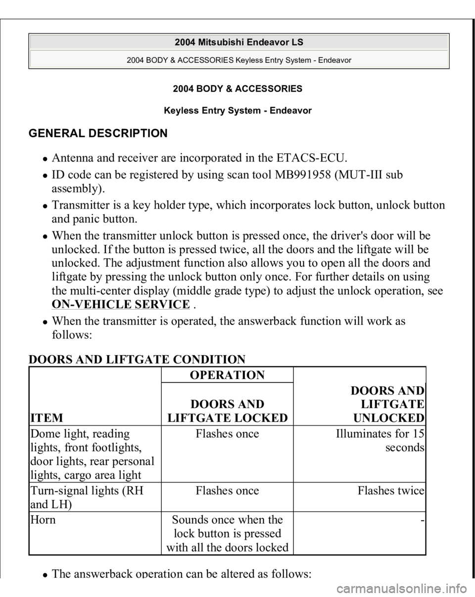
When the transmitter is operated, the answerback function will work as
follows:
DOORS AND LIFTGATE CONDITION The answerback o
peration can be altered as follows:
ITEM
OPERATIONDOORS AND
LIFTGATE LOCKED
DOORS AND
LIFTGATE
UNLOCKED
Dome light, reading
lights, front footlights,
door lights, rear personal
lights, cargo area light
Flashes once
Illuminates for 15
seconds
Turn-signal lights (RH
and LH)
Flashes once
Flashes twice
Horn
Sounds once when the
lock button is pressed
with all the doors locked
-
2004 Mitsubishi Endeavor LS
2004 BODY & ACCESSORIES Keyless Entry System - Endeavor
2004 Mitsubishi Endeavor LS
2004 BODY & ACCESSORIES Keyless Entry System - Endeavor
Page 2727 of 3870
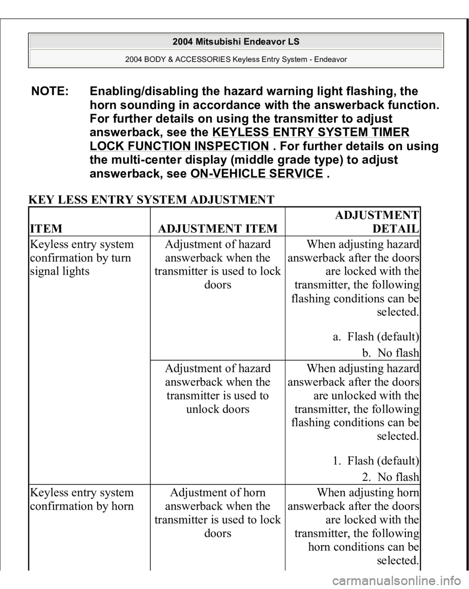
KEY LESS ENTRY SYSTEM ADJUSTMENT NOTE: Enabling/disabling the hazard warning light flashing, the
horn sounding in accordance with the answerback function.
For further details on using the transmitter to adjust
answerback, see the KEYLESS ENTRY SYSTEM TIMER
LOCK FUNCTION INSPECTION
. For further details on using
the multi-center display (middle grade type) to adjust
answerback, see ON
-VEHICLE SERVICE
.
ITEM
ADJUSTMENT ITEM
ADJUSTMENT
DETAIL
Keyless entry system
confirmation by turn
signal lights
Adjustment of hazard
answerback when the
transmitter is used to lock
doors
When adjusting hazard
answerback after the doors
are locked with the
transmitter, the following
flashing conditions can be
selected.
a. Flash (default)
b. No flash
Adjustment of hazard
answerback when the
transmitter is used to
unlock doors
When adjusting hazard
answerback after the doors
are unlocked with the
transmitter, the following
flashing conditions can be
selected.
1. Flash (default)
2. No flash
Keyless entry system
confirmation by horn
Adjustment of horn
answerback when the
transmitter is used to lock
doors
When adjusting horn
answerback after the doors
are locked with the
transmitter, the following
horn conditions can be
selected.
2004 Mitsubishi Endeavor LS
2004 BODY & ACCESSORIES Keyless Entry System - Endeavor
Page 2731 of 3870
1. Operate the transmitter to check that the doors and liftgate can be locked and
unlocked.
2. Operate the transmitter to check that the answerback function works in
response to door and liftgate locking/unlocking.
NOTE: The adjustment function allows you to change the
unlock operation setting as follows. Prior to that check,
confirm which setting is activated.
a. When the unlock button is pressed once, the
driver's door will be unlocked. Then when the
button is pressed once again, all the doors and
liftgate will be opened (initial setting).
b. When the unlock button is pressed only once, all
the doors and liftgate will be opened.
NOTE: The adjustment function allows you to change the
hazard answerback setting as follows. Prior to that
check, confirm which setting is activated.
a. Turn-signal lights: Flash once when doors and
liftgate are locked, and twice when unlocked (initial
setting)
b. Turn-signal lights: Flash once when doors and
liftgate are locked, but does not flash when
unlocked.
c. Turn-signal lights: Do not flash when doors and
liftgate are locked, but flash twice when unlocked.
d. Turn-signal lights: Do not flash when doors and
liftgate are locked and unlocked.
NOTE: The adjustment function allows you to change the horn
answerback setting as follows. Prior to that check,
confirm which setting is activated.
2004 Mitsubishi Endeavor LS
2004 BODY & ACCESSORIES Keyless Entry System - Endeavor
Page 2732 of 3870
KEYLESS ENTRY SYSTEM TIMER LOCK FUNCTION INSPECTION If the doors and liftgate are not locked within 30 seconds after the unlock button is
pressed, refer to SWS DIAGNOSIS
.
ENABLING/DISABLING THE ANSWERBACK FUNCTION When the doors and liftgate are locked or unlocked by using the transmitter, the
dome light will flash/illuminate, the turn-signal lights will flash (hazard
answerback), or the horn will sound (horn answerback) to inform the driver.
The hazard answerback and horn answerback functions can be enabled or disabled
according to the following procedure: ENABLING/DISABLING THE HAZARD ANSWERBACK FUNCTION HOW TO ADJUST HAZARD ANSWERBACK WHEN THE TRANSMITTER IS USED TO LOCK DOORS 1. Remove the ignition key.
2. Push the "LOCK" button while holding the "UNLOCK" button pushed for four
to ten seconds.
3. If the "LOCK" button and "UNLOCK" button are released in that order
, the
1. Horn: Sounds once when the lock button is
pressed.
2. Horn: Sounds once when the lock button is pressed
(initial setting).
3. Horn: Does not sound.
NOTE: If either of the doors is opened or the key is inserted in the
ignition switch within that 30-second period, the timer lock
function will be cancelled.
NOTE: The adjustment function allows you to change the timer
lock period from 30 seconds (initial setting) to 60, 120 or
180 seconds. Prior to this inspection, confirm which setting
is activated.
2004 Mitsubishi Endeavor LS
2004 BODY & ACCESSORIES Keyless Entry System - Endeavor
Page 3163 of 3870
Courtesy of MITSUBISHI MOTOR SALES OF AMERICA
.
2. Start the engine.
3. Set scan tool MB991958 to the data reading mode, and check the data list
items by driving the vehicle.
Item 01 (DTC C1200 is set): Front right ABS sensor Item 02 (DTC C1205 is set): Front left ABS sensor Item 03 (DTC C1210 is set): Rear right ABS sensor Item 04 (DTC C1215 is set): Rear left ABS sensor
4. Turn the ignition switch to the "LOCK" (OFF) position.
Q: Does the speedometer indication match the scan tool indication?
YES: It can be assumed that this malfunction is intermittent.
Refer to HOW TO COPE WITH INTERMITTENT
MALFUNCTIONS
.
NO: Go to Step 4.
STEP 4. Measure the voltage at TCL/ASC-ECU connector A-32.
1. Disconnect the connector A-32, and connect special tool ABS Check
Harness (MB991952) to the wiring harness-side connector.
2. Turn the ignition switch to the "ON" position.
3. Measure the voltage between the relevant signal and ground terminals in
the ABS sensor circuit and body ground. It should be less than 1V.
DTC C1200 is set: Between signal terminal 30 and body ground, and
between ground terminal 21 and body ground DTC C1205 is set: Between signal terminal 22 and body ground, and
between ground terminal 31 and body ground DTC C1210 is set: Between si
gnal terminal 8 and bo
dy ground, and
NOTE: Do not connect special tool ABS Check Harness
(MB991952) to the TCL/ASC-ECU.
2004 Mitsubishi Endeavor LS
2004 BRAKES Traction Control, Active Skid Control System - Endeavor
Page 3193 of 3870
Courtesy of MITSUBISHI MOTOR SALES OF AMERICA
.
6. Turn the ignition switch to the "LOCK" (OFF) position.
Q: Is DTC C1200, C1205, C1210 or C1215 set?
YES: Repeat the troubleshooting from Step 1.
NO: The procedure is complete.
DTC C1201: FR WHEEL SPD. SNSR. INVALID SIGNAL, DTC C1206: FL WHEEL SPD. SNSR. INVALID SIGNAL,
DTC C1211: RR WHEEL SPD. SNSR. INVALID SIGNAL, DTC C1216: RL WHEEL SPD. SNSR. INVALID SIGNAL
2004 Mitsubishi Endeavor LS
2004 BRAKES Traction Control, Active Skid Control System - Endeavor