Page 1220 of 3870
Courtesy of MITSUBISHI MOTOR SALES OF AMERICA
.
STEP 14. Check the symptoms.
Q: Do the radiator fan and condenser fan operate correctly?
YES: The procedure is complete.
NO: Return to Step 1 .
INSPECTION PROCEDURE 4: Radiator Fan and Condenser Fan do not Change Speed or Stop Radiator Fan and Condenser Fan Drive Circuit Refer to INSPECTION PROCEDURE 3: RADIATOR FAN AND CONDENSER FAN DO NOT OPERATE
.
CIRCUIT OPERATION
The fan control module is powered from fusible link number 2. The PCM judges the required revolution speed of radiator fan motor and
condenser fan motor using the input signals transmitted from A/C switch,
automatic compressor controller, vehicle speed sensor and engine coolant
temperature sensor. The PCM activates the fan control module to drive the
radiator fan motor and condenser fan motor.
TECHNICAL DESCRIPTION The fan controller has variable control of the radiator fan motor and the condenser
fan motor speeds using signals transmitted from the PCM. TROUBLESHOOTING HINTS NOTE: If the engine coolant temperature reaches 110°C (230°F) or
higher, the radiator fan control runs the radiator fan for up
to 5 minutes even after the ignition switch is turned to the
"LOCK" (OFF) position [the fan stops its rotation when the
engine coolant temperature decreases to 110°C (230° F) or
lower.]
2004 Mitsubishi Endeavor Limited 2004 ENGINE Engine Cooling - Endeavor
Page 1235 of 3870
NO: Replace the radiator fan motor. Then go to Step 7.
STEP 7. Check the symptoms.
Q: Do the radiator fan and condenser fan operate correctly?
YES: The procedure is complete.
NO: Return to Step 1 .
INSPECTION PROCEDURE 5: Radiator Fan does not Operate TECHNICAL DESCRIPTION The cause could be a malfunction of the radiator fan motor or an open circuit
between the fan control module and the radiator fan motor. TROUBLESHOOTING HINTS Malfunction of radiator fan motor DIAGNOSIS Replace the radiator fan motor. INSPECTION PROCEDURE 6: Condenser Fan does not Operate Radiator Fan and Condenser Fan Drive Circuit Refer to INSPECTION PROCEDURE 3: RADIATOR FAN AND CONDENSER FAN DO NOT OPERATE
.
CIRCUIT OPERATION
The fan control module is powered from fusible link number 2. The PCM judges the required revolution speed of radiator fan motor and
condenser fan motor using the input signals transmitted from A/C switch,
automatic compressor controller, vehicle speed sensor and engine coolant
temperature sensor. The PCM activates the fan control module to drive the
radiator fan motor and condenser fan motor.
TECHNICAL DESCRIPTION
2004 Mitsubishi Endeavor Limited 2004 ENGINE Engine Cooling - Endeavor
Page 1774 of 3870
7. Does vehicle have an antenna which extend? If not eliminate this step.
If there is noise, the following causes can be considered.
8. If due to vehicle noise: It may not be possible to prevent noise if the signal is
weak.
9. If due to external noise: In almost all cases, prevention on the receiver side is
not possible. Weak signals especially are susceptible to interference.
If there is more noise than on radios in other vehicles, find out the noise condition
and the name and frequency of the receiving stations from the owner, and consult
with the radio manufacturer's service center. INSPECTION PROCEDURE 10: Sound mixed with Noise, Only at Night (AM). The following can be considered as possible causes of noise appearing only at
night.
1. It is significantly easier to receive long-distance signals at night. This means
that even stations that are received without a problem during the day may
experience problems at night. Remember that the weaker station is more
susceptible to interference. The appearance of a beat sound may occur in the
evening. A beat sound is created when two signals close in frequency interfere
with each other. A common sign of this type of interference is a repetitious
high-pitched sound that may over power the desired radio station. This sound is
generated not only by sound signals but electrical waves as well.
2. The changing system may also be a source of noise. When diagnosing radio
noise, do not over look the possibility of a problem with the vehicles generator. DIAGNOSIS
STEP 1. Check the vehicles lighting system.
Q: Does the noise disappear when the vehicles headlights are turned
"OFF"?
YES: Go to Ste
p 2.
2004 Mitsubishi Endeavor LS
2004 BODY & ACCESSORIES Radio With Tape Player & Cd Player - Endeavor
Page 1788 of 3870
Q: Is the problem station or location specific?
YES: The effect of an electrical field condition (multipath noise, fading
noise) could be the cause. Check that there is not noise.
NO: Go to Step 4.
STEP 4. Check that noise appears when the radio switch is turned on
while the vehicle is stopped.
Q: Does noise appear when the radio switch is turned on while the vehicle
is stopped and the radio is tapped while tuned away from a station?
YES: Go to Step 5.
NO: It may be static electricity noise.
STEP 5. Verify that the radio is correctly grounded.
The radio is connected to the ground with an assembling screw.
Q: Is the radio correctly grounded?
YES: Go to Step 6.
NO: Tighten the screw securely. Check that there is no noise.
Fading noise
This is a buzzing noise that occurs when the
broadcast signal is disrupted by obstructing
objects and the signal strength fluctuates intricately
within a narrow range.
NOTE: Body static electricity from the shock absorber rubber
bushings used to prevent vibration, tires, etc. occurs
because of separation from the ground, causing a
buzzing noise. There is no measures to discharge the
static electricity of the vehicle body. Check that there is
no noise.
2004 Mitsubishi Endeavor LS
2004 BODY & ACCESSORIES Radio With Tape Player & Cd Player - Endeavor
Page 2141 of 3870
2. Turn the ignition switch to the "ON" position.
3. Check if the DTC is set.
4. Turn the ignition switch to the "LOCK" (OFF) position. Q: Is the check result satisfactory?
YES:
There is an intermittent malfunction such as poor engaged connector
(s) or open circuit (Refer to
HOW TO USE TROUBLESHOOTING/
INSPECTION SERVICE POINTS
).
NO:
Replace the A/C-ECU. On completion, check that the DTC is not
reset.
DTC U1100: POWERTRAIN CONTROL MODULE TIME-OUT (RELATED TO ENGINE) TROUBLE JUDGMENT The A/C-ECU receives engine control system-related signal from the powertrain
control module. If the ECU cannot receive the signal, DTC U1100 will be set. TECHNICAL DESCRIPTION (COMMENT)
CURRENT TROUBLE
Connector(s) or wiring harness in the CAN bus lines between the powertrain
control module and the A/C-ECU, the power supply system to the powertrain
control module, the powertrain control module itself, or the A/C-ECU may be
defective.
PAST TROUBLE
If DTC U1100 is stored as a past trouble, carry out diagnosis with particular
emphasis on wiring and connector(s) in the CAN bus line between the A/C-
ECU
and the powe
rtrain
control m
odu
le, and the powe
r supp
ly syste
m to the
CAUTION: If DTC U1100 is set in the A/C-ECU, diagnose the
CAN main bus line.
CAUTION: Whenever the ECU is replaced, ensure that the
communication circuit is normal.
2004 Mitsubishi Endeavor LS
2004 HVAC Heater Air Conditioning, Ventilation - Endeavor
Page 2378 of 3870
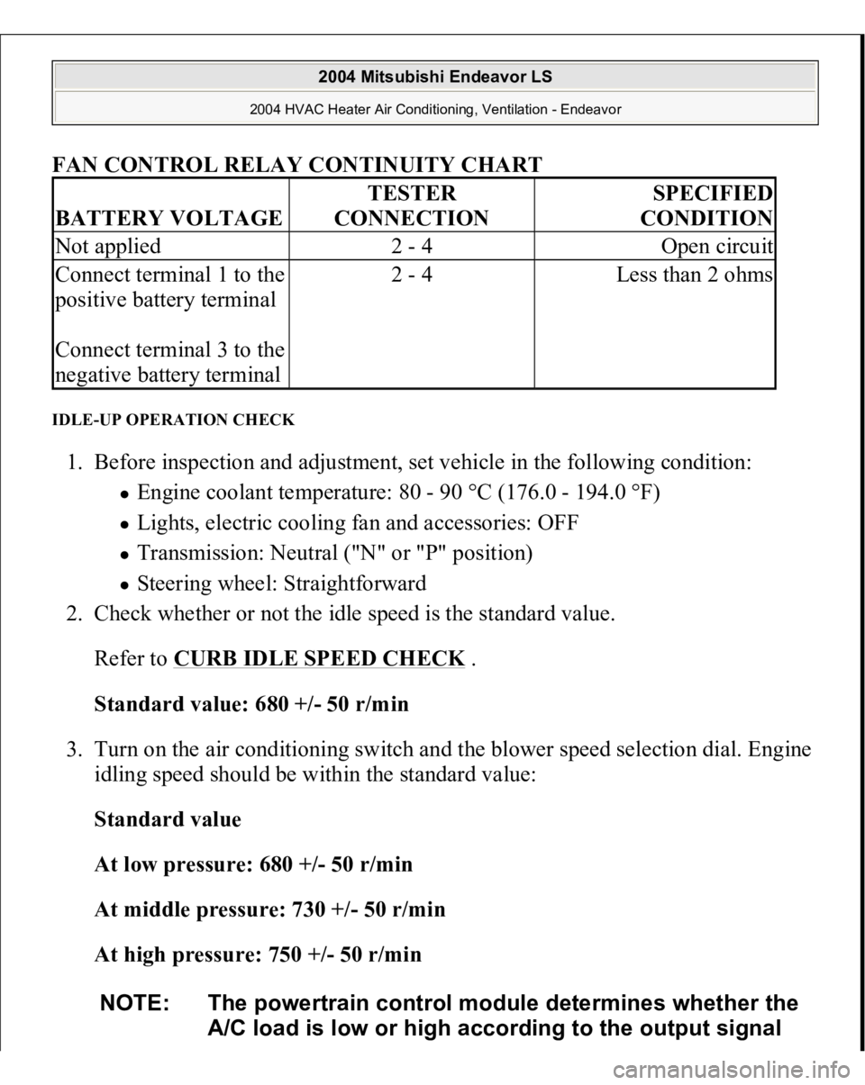
FAN CONTROL RELAY CONTINUITY CHART
IDLE-UP OPERATION CHECK 1. Before inspection and adjustment, set vehicle in the following condition:
Engine coolant temperature: 80 - 90 °C (176.0 - 194.0 °F) Lights, electric cooling fan and accessories: OFF Transmission: Neutral ("N" or "P" position) Steering wheel: Straightforward
2. Check whether or not the idle speed is the standard value.
Refer to
CURB IDLE SPEED CHECK
.
Standard value: 680 +/- 50 r/min
3. Turn on the air conditioning switch and the blower speed selection dial. Engine
idling speed should be within the standard value:
Standard value
At low pressure: 680 +/- 50 r/min
At middle pressure: 730 +/- 50 r/min
At high pressure: 750 +/- 50 r/min
BATTERY VOLTAGE
TESTER
CONNECTION
SPECIFIED
CONDITION
Not applied
2 - 4
Open circuit
Connect terminal 1 to the
positive battery terminal
Connect terminal 3 to the
negative battery terminal
2 - 4
Less than 2 ohms
NOTE: The powertrain control module determines whether the
A/C load is low or high according to the output signal
2004 Mitsubishi Endeavor LS
2004 HVAC Heater Air Conditioning, Ventilation - Endeavor
Page 2438 of 3870
Courtesy of MITSUBISHI MOTOR SALES OF AMERICA
.
Q: Is the check result satisfactory?
YES:
Go to Step 2.
NO:
Repair the CAN bus lines (Refer to
CAN COMMUNICATION
SIGNAL TABLE
). Then go to Step 7 .
STEP 2. Recheck for diagnostic trouble code.
Recheck if the DTC is set.
1. Erase the DTC.
2. Turn the ignition switch to "ON" position.
3. Check if the DTC is set.
Q: Is the check result satisfactory?
YES:
It can be assumed that this malfunction is intermittent. Refer to
HOW TO USE TROUBLESHOOTING/INSPECTION SERVICE POINTS
.
NO:
Go to Step 3.
STEP 3. Using scan tool MB991958, check data list item 01: interior
temperature sensor.
1. Connect scan tool MB991958 to the data link connector.
2. Start the engine.
3. Check the data list.
Item 01: Interior temperature sensor.
Check that the ambient tem
perature matches the dis
played value on
CAUTION: To prevent damage to scan tool MB991958,
always turn the ignition switch to the
"LOCK" (OFF) position before connecting or
disconnecting scan tool MB991958.
2004 Mitsubishi Endeavor LS
2004 HVAC Automatic Air Conditioning - Endeavor
Page 2551 of 3870
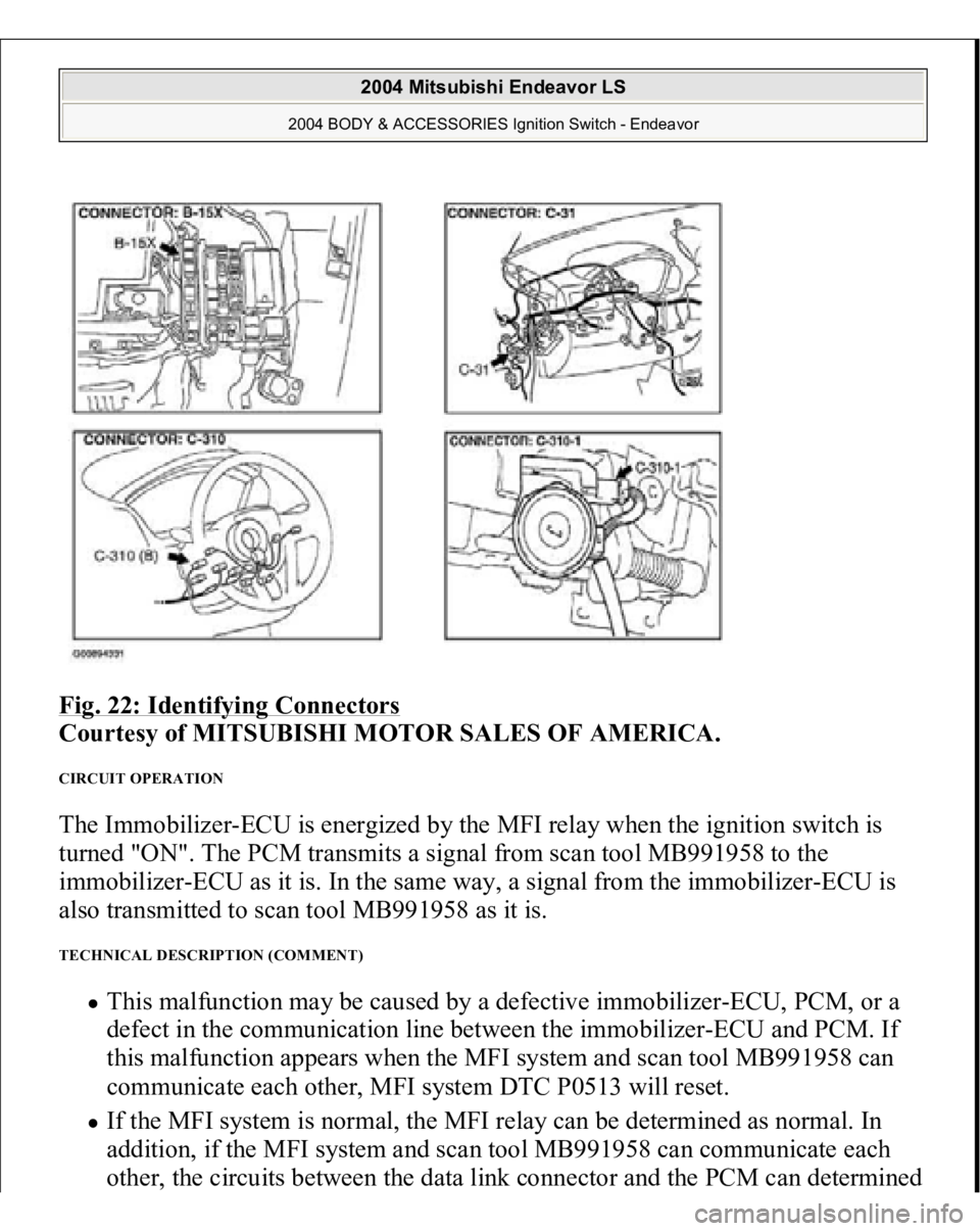
Fig. 22: Identifying Connectors
Courtesy of MITSUBISHI MOTOR SALES OF AMERICA.
CIRCUIT OPERATION The Immobilizer-ECU is energized by the MFI relay when the ignition switch is
turned "ON". The PCM transmits a signal from scan tool MB991958 to the
immobilizer-ECU as it is. In the same way, a signal from the immobilizer-ECU is
also transmitted to scan tool MB991958 as it is. TECHNICAL DESCRIPTION (COMMENT)
This malfunction may be caused by a defective immobilizer-ECU, PCM, or a
defect in the communication line between the immobilizer-ECU and PCM. If
this malfunction appears when the MFI system and scan tool MB991958 can
communicate each other, MFI system DTC P0513 will reset. If the MFI system is normal, the MFI relay can be determined as normal. In
addition, if the MFI system and scan tool MB991958 can communicate each
other, the circuits between the data link connecto
r and the PCM can determined
2004 Mitsubishi Endeavor LS
2004 BODY & ACCESSORIES Ignition Switch - Endeavor