Page 960 of 4264
8A-302 ELECTRICAL-BODY AND CHASSIS
TROUBLESHOOTING
QUICK CHART FOR CHECK POINTS
Check Points
Fuse
C-14
(20A) Power
Window &
Door Lock
Switch Door
Lock
SwitchKey CYLN
Der switch Door Lock Actuator
Cable
Trouble Mode Driver’s
side Driver’s
side D/S P/S Passen
ger’s
side RR-RH RR-LHHarness
1. All the doors do not
lock and unlock
2. All the doors do not
get locked (or
unlocked)
3. Driver’s side door
does not get locked
(or unlocked)
4. FRT passenger’s side
door does not get
locked (or unlocked)
5. RR door-RH does not
get locked (or
unlocked)
6. RR door-LH does not
get locked (or
unlocked)
7. Door lock does not
operate when
operating from the
driver’s seat side
Page 961 of 4264

Poor fuse contact or b")
ELECTRICAL-BODY AND CHASSIS 8A-303
1. All the doors do not lock and unlock
Checkpoint Trouble Cause Countermeasure
Reinstall or replace the fuse
No. C-14 (20A)
Poor fuse contact or blown
NG
Repair grounding point
C-2
contact
Grounding point
C-2
Poor grounding point contact
Repair open circuit or
connector contact
Voltage between the driver’s
side power window & door
lock SW harness side
connector terminal 1
D-5
and the ground (Should be
battery voltage present)
Open circuit or poor connector
contact
NG NG OK
OK OK
Fuse No. C-14 (20A, Fuse
box)
Repair open circuit or
connector contact
Open circuit or poor connector
contact
NG
Replace the driver’s side
power window & door lock
SW.
Driver’s side power window &
door lock SW. function
SW. malfunction
NG OK
Continuity between 4
D-4
and
C-2
2. All the doors do not get locked (or unlocked)
Repair open circuit or
connector contact
Open circuit or poor connector
contact
NG
Replace the driver’s side
power window & door lock
SW.
Driver’s side power window &
door lock SW. function
SW. malfunction
NG OK
Continuity between the driver’s
side power window & door
lock SW harness side
connector terminals 14
D-20
and 6
D-20
Page 965 of 4264
ELECTRICAL-BODY AND CHASSIS 8A-307
INSPECTION AND REPAIR
Harness side
D-20 D-5
Driver Seat Side Power Window & Door Lock
Switch
1. Harness Side Connector Circuit
Check voltage and continuity between the switch harness
side connector terminals as shown in the following table.
Terminal
No. Wire
color Connecting to Check itemConnectin
g terminalCheck condition Standard
Door lock SW
Driver seat Lock Continuity
(Lock) side door
Unlock No continuity
Door lock SW
Driver seat Lock No continuity
(Unlock) side door
Unlock Continuity
3 (D-5) L/R Ground
Continuity 3-Ground - Continuity
4 (D-5)
L/R Door lock
actuator (Lock) (Resistance)
4-5
- Continuity
There is some
resistance
5 (D-5)
L Door lock
actuator
(Unlock)
5-4
- Continuity
There is some
resistance
1 (D-5) LG/W Fuse
C-14 (20A) Voltage 1- Ground - Battery voltage
(Approx. 12V)
14-Ground L/R 14 (D-20)
13-Ground L/Y
13 (D-20)
Page 975 of 4264

Poor fuse cont")
ELECTRICAL-BODY AND CHASSIS 8A-317
DIESEL W/SRS MODEL
1. All windows do not operate
Checkpoint Trouble Cause Countermeasure
Reinstall or replace the fuse
SBF-11 (30A)
Poor fuse contact or blown
NG
Replace the circuit breaker
SBF-9 (50A)
SBF-9 (50A, Fuse box)
function
Circuit breaker malfunction
Repair grounding points
C-2
contact
Grounding points
C-2
Poor grounding point contact
NG NG OK
OK OK
Fuse SBF-11 (30A, Fuse box)
Replace the power window
relay
Power window relay
malfunction
NG
Repair an open circuit or a
poor connection of the
connectors between 1
C-108
and 2
B-8
Voltage between the power
window relay harness side
connector terminal 2
B-8
and the ground (Should be
battery voltage present)
Open circuit or poor connector
contact
NG OK
Power window relay function
OK
Repair an open circuit or a
poor connection of the
connectors between 1
B-8
and 1
B-56 and 6 D-5
Open circuit or poor connector
contact
NG Voltage between 6 D-5 and
the ground (Should be battery
voltage present)
OK
Repair an open circuit or a
poor connection of the
connectors between 3
D-5
and
C-2 , or 3 B-8 (12
C-107 )
and C-2
Open circuit or poor connector
contact
NG
Continued on the next page
Voltage between
C-2 and
the ground
Page 993 of 4264

ELECTRICAL-BODY AND CHASSIS 8A-335
TROUBLESHOOTING
CIGARETTE LIGHTER
1. Lighter does not pop out after being pushed in. It does not become hot.
Checkpoint Trouble Cause Countermeasure
Reinstall or replace the fuse
No. C-12 (15A)
Poor Fuse No. C-12 (15A,
Fuse box) contact or blown
NG
Replace the lighter
Lighter continuity between
center part and outer area
Open circuit or poor connector
contact
Repair open circuit or
connector contact
Voltage between connector 1
B-21 and the ground at
starter SW. is ACC position
(Should be battery voltage
present)
Open circuit or poor connector
contact
NG NG OK
OK OK
Audio system (System should
receive power)
Repair open circuit or
connector contact
Open circuit or poor connector
contact
NG
Continuity between connector
1
B-22 and the ground
2. Lighter pops out prematurely before becoming hot
Repair or replace the lighter
and/or casingDeformed lighter or casing NGLighter and casing
3. Lighter becomes too hot
Repair or replace the lighter
and/or casingDeformed lighter and casing NGLighter and casing
Page 999 of 4264
ELECTRICAL-BODY AND CHASSIS 8A-341
TROUBLESHOOTING
QUICK CHART FOR CHECK POINT
Check Point Fuse
Door Mirror Door Mirror
Trouble Mode C-11
(10A) Control
Switch LH RH
1. Mirrors on the both sides do not operate
2. Mirror on the left (or right) side does not
operate
3. Mirrors on the both sides operate only in
the vertical
(or horizontal) direction
4. Mirror on the left side operates only in
the vertical
(or horizontal)direction
5. Mirror on the right side operates only in
the vertical
(or horizontal) direction
Cable
Harness
Page 1000 of 4264

8A-342 ELECTRICAL-BODY AND CHASSIS
DOOR MIRROR CONTROL SWITCH
1. Mirrors on the both sides do not operate
Checkpoint Trouble Cause Countermeasure
Reinstall or replace the fuse
No. C-11 (10A)
Poor fuse contact or blown
NG
Repair grounding point
C-2
contact
Grounding point
C-2
Poor grounding point contact
Repair an open circuit or a
poor connection of the
connectors between the fuse
No. C-11 (10A) and 4
D-19
Voltage between the door
mirror control SW. harness
side connector terminal
4
D-19 and the ground
(Should be battery voltage
present)
Open circuit or poor connector
contact
NG NG OK
OK OK
Fuse No. C-11 (10A, Fuse
box)
Repair open circuit or
connector contact
Open circuit or poor connector
contact
NG Continuity between the door
mirror control SW harness
side connector terminal
8
D-19 and C-2
Replace the door mirror
control SW.
Door mirror control SW.
function
SW. malfunction
NG OK
Repair open circuit or
connector contact
Continuity between 7
D-19
and 2
H-24 (or 2 H-25 )
Open circuit or poor connector
contact
NG OK
Page 1005 of 4264
ELECTRICAL-BODY AND CHASSIS 8A-347
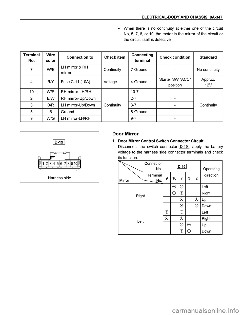
� When there is no continuity at either one of the circuit
No, 5, 7, 8, or 10, the motor in the mirror of the circuit or
the circuit itself is defective.
Terminal
No. Wire
color Connection to Check item Connecting
terminal Check condition Standard
7 W/B LH mirror & RH
mirror Continuity 7-Ground - No continuity
4 R/Y Fuse C-11 (10A) Voltage 4-Ground Starter SW “ACC”
position Approx.
12V
10 W/R RH mirror-LH/RH 10-7 -
2 B/W RH mirror-Up/Down 2-7 -
3 B/R LH mirror-Up/Down Continuity 3-7 - Continuity
8 B Ground 8-Ground -
9 W/G LH mirror-LH/RH 9-7 -
Harness side
D-19
Door Mirror
1. Door Mirror Control Switch Connector Circuit
Disconnect the switch connector
D-19 , apply the battery
voltage to the harness side connector terminals and check
its function.
Connector
No. D-19
Operating
Terminal
Mirror No.9 10 7 3 2direction
+ - Left
- + Right
- +Up
+ -Down
+ - Left
- + Right
- + Up
+ - Down
Left Right
 Power
Window &
Door Lock
Switch Door
Lock
SwitchKey CYLN
Der switch Door")

 Control
Switch LH RH
1. Mirrors on th")