Page 1011 of 4264

ELECTRICAL-BODY AND CHASSIS 8A-353
TROUBLE SHOOTING
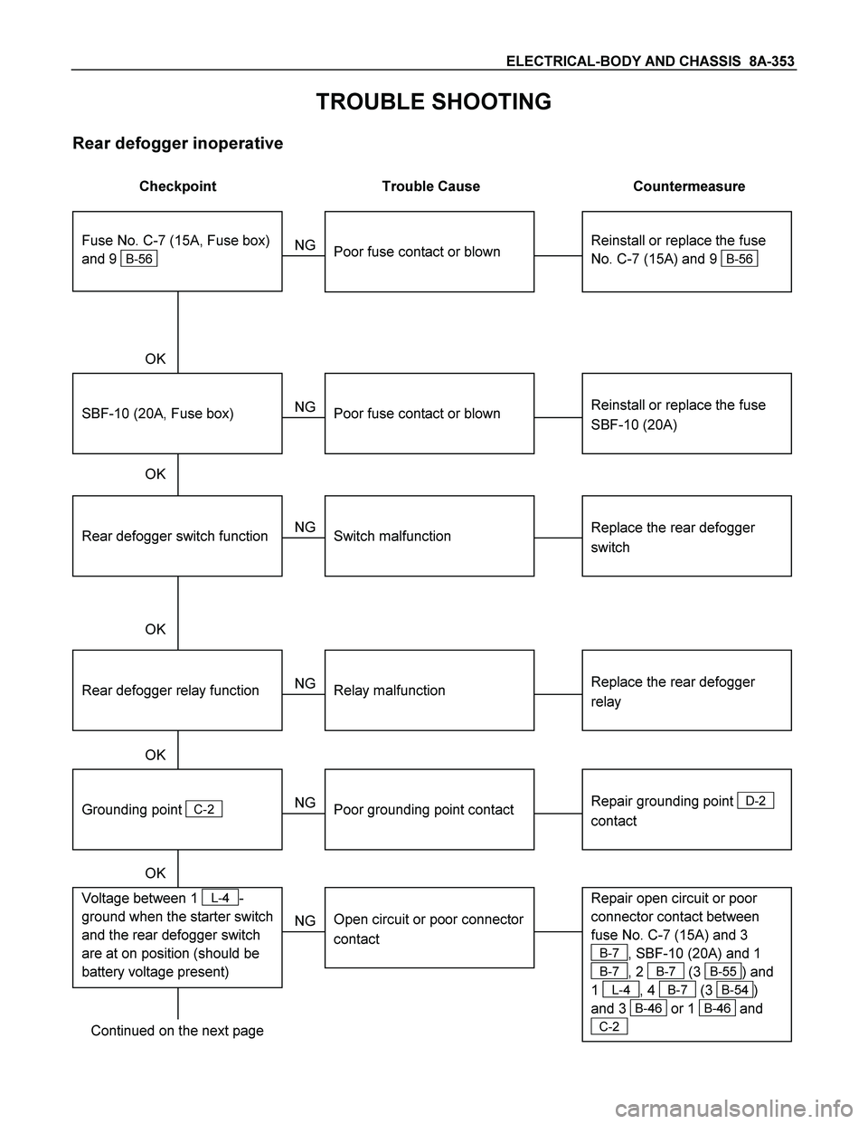
Rear defogger inoperative
Checkpoint Trouble Cause Countermeasure
Reinstall or replace the fuse
No. C-7 (15A) and 9
B-56
Poor fuse contact or blown
NG
Reinstall or replace the fuse
SBF-10 (20A)
SBF-10 (20A, Fuse box)
Poor fuse contact or blown
Replace the rear defogger
switch
Rear defogger switch function
Switch malfunction
NG NG OK
OK OK
Fuse No. C-7 (15A, Fuse box)
and 9
B-56
Replace the rear defogger
relay
Relay malfunction
NG
Continued on the next page
Rear defogger relay function
Repair grounding point
D-2
contact
Grounding point
C-2
Poor grounding point contact
NG OK
Repair open circuit or poor
connector contact between
fuse No. C-7 (15A) and 3
B-7, SBF-10 (20A) and 1
B-7, 2 B-7 (3 B-55) and
1
L-4, 4 B-7 (3 B-54)
and 3
B-46 or 1 B-46 and
C-2
Voltage between 1 L-4-
ground when the starter switch
and the rear defogger switch
are at on position (should be
battery voltage present)
Open circuit or poor connector
contact
NG OK
Page 1095 of 4264
ELECTRICAL-BODY AND CHASSIS 8A-437
No. Connector face No. Connector face
P-1
Silver
Battery (+) P-9
SilverACG (B)
P-2
Silver
Relay & Fuse box P-10
SilverEngine ground
P-3
Brown
Starter (S) P-11
SilverFuse & relay box
P-4
Silver
Starter (B) P-12
NOT USED
P-4
Silver
Starter (B) P-13
Gray Shift on the fly actuator
P-5
Silver
Battery (-) P-14
WhiteFuse & relay box
P-6
Silver
Body earth (Ground) P-15
Silver2nd battery (+)
P-7
NOT USED P-16
Silver
2nd battey (-)
P-8
(C24SE)
(4JH1-TC
Green ACG (L)
P-8
(6VE1)
White ACG (L)
Page 1123 of 4264

TROUBLESHOOTING 6 – 3
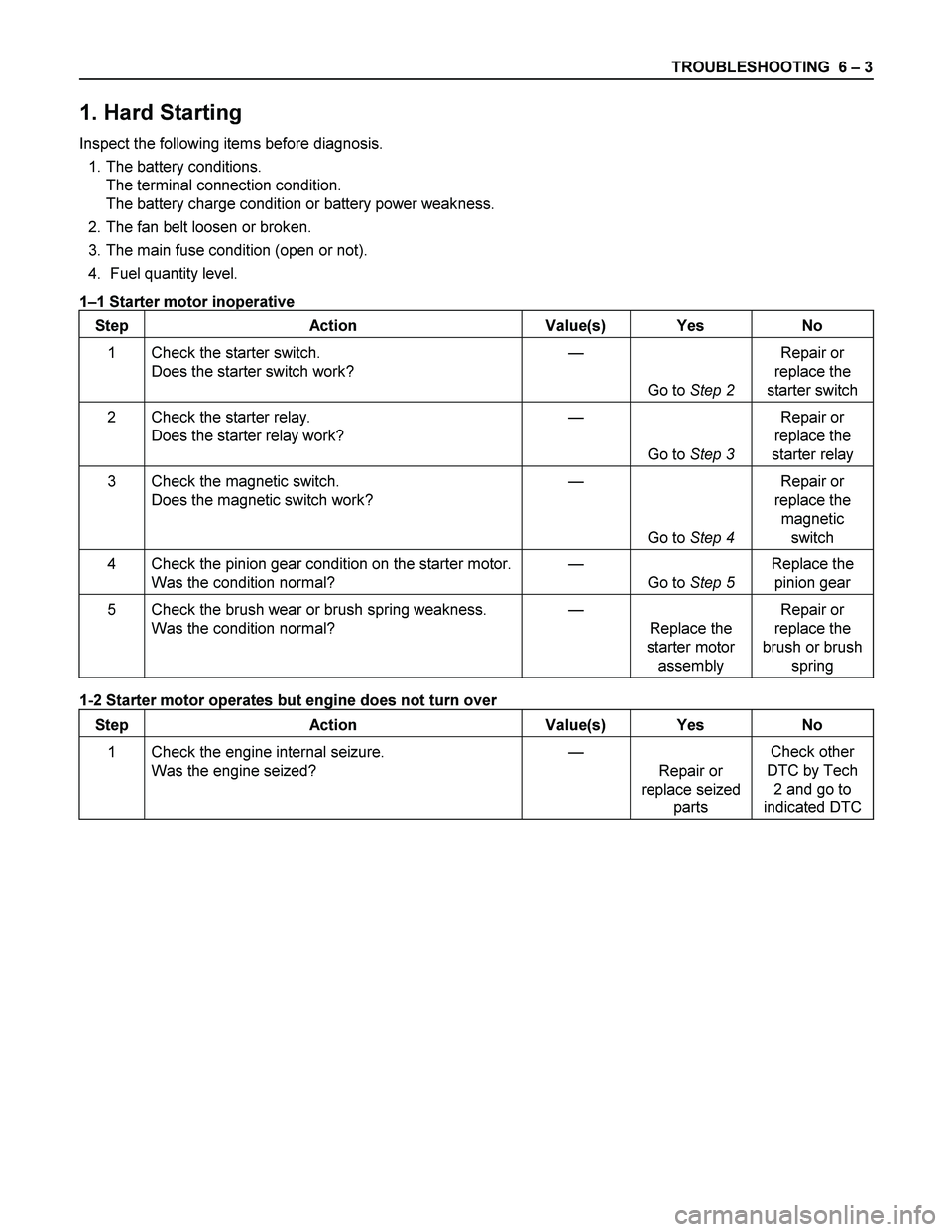
1. Hard Starting
Inspect the following items before diagnosis.
1. The battery conditions.
The terminal connection condition.
The battery charge condition or battery power weakness.
2. The fan belt loosen or broken.
3. The main fuse condition (open or not).
4. Fuel quantity level.
1–1 Starter motor inoperative
Step Action Value(s) Yes No
1 Check the starter switch.
Does the starter switch work? —
Go to Step 2 Repair or
replace the
starter switch
2 Check the starter relay.
Does the starter relay work? —
Go to Step 3 Repair or
replace the
starter relay
3 Check the magnetic switch.
Does the magnetic switch work? —
Go to Step 4 Repair or
replace the
magnetic
switch
4 Check the pinion gear condition on the starter motor.
Was the condition normal? —
Go to Step 5 Replace the
pinion gear
5 Check the brush wear or brush spring weakness.
Was the condition normal? —
Replace the
starter motor
assembly Repair or
replace the
brush or brush
spring
1-2 Starter motor operates but engine does not turn over
Step Action Value(s) Yes No
1 Check the engine internal seizure.
Was the engine seized? —
Repair or
replace seized
parts Check other
DTC by Tech
2 and go to
indicated DTC
Page 1371 of 4264
ENGINE ELECTRICAL 6D – 33
PRE-HEATING SYSTEM
INSPECTION AND REPAIR
Make the necessary adjustments, repairs, and part replacement if excessive wear of damage is discovered during
inspection.
VISUAL CHECK
Check the main fuses and glow indicator for damage.
Replace the part(s) if required.
GLOW RELAY
The glow relay is located in the relay box the engine
compartment.
825R300046
Use an ohmmeter to measure the resistance between
terminals No.2 and No.3.
If the measured value is outside the specified range, the
glow relay must be replaced.
Glow Relay Resistance Ohms
94 � 114
GLOW PLUG
LNW21KSH001401
Use a circuit tester to test the glow plugs for continuity.
Glow Plug Resistance (Reference) Ohms
Approximately 0.9
EGR SYSTEM 4JA1T (L)
Refer to 6F-9. (EGR system diagram)
Page 1373 of 4264

4JA1/4JH1 ENGINE DRIVEABILITY AND EMISSIONS 6E–1
ENGINE
CONTENTS
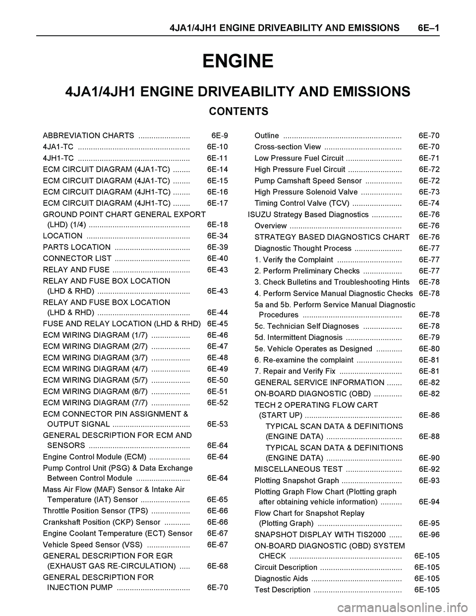
4JA1/4JH1 ENGINE DRIVEABILITY AND EMISSIONS
ABBREVIATION CHARTS ........................ 6E-9
4JA1-TC .................................................... 6E-10
4JH1-TC .................................................... 6E-11
ECM CIRCUIT DIAGRAM (4JA1-TC) ........ 6E-14
ECM CIRCUIT DIAGRAM (4JA1-TC) ........ 6E-15
ECM CIRCUIT DIAGRAM (4JH1-TC) ........ 6E-16
ECM CIRCUIT DIAGRAM (4JH1-TC) ........ 6E-17
GROUND POINT CHART GENERAL EXPORT
(LHD) (1/4) ............................................... 6E-18
LOCATION ................................................ 6E-34
PARTS LOCATION ................................... 6E-39
CONNECTOR LIST ................................... 6E-40
RELAY AND FUSE .................................... 6E-43
RELAY AND FUSE BOX LOCATION
(LHD & RHD) ........................................... 6E-43
RELAY AND FUSE BOX LOCATION
(LHD & RHD) ........................................... 6E-44
FUSE AND RELAY LOCATION (LHD & RHD) 6E-45
ECM WIRING DIAGRAM (1/7) .................. 6E-46
ECM WIRING DIAGRAM (2/7) .................. 6E-47
ECM WIRING DIAGRAM (3/7) .................. 6E-48
ECM WIRING DIAGRAM (4/7) .................. 6E-49
ECM WIRING DIAGRAM (5/7) .................. 6E-50
ECM WIRING DIAGRAM (6/7) .................. 6E-51
ECM WIRING DIAGRAM (7/7) .................. 6E-52
ECM CONNECTOR PIN ASSIGNMENT &
OUTPUT SIGNAL .................................... 6E-53
GENERAL DESCRIPTION FOR ECM AND
SENSORS ............................................... 6E-64
Engine Control Module (ECM) ................... 6E-64
Pump Control Unit (PSG) & Data Ex change
Between Control Module ......................... 6E-64
Mass Air Flow (MAF) Sensor & Intake Air
Temperature (IAT) Sensor ....................... 6E-65
Throttle Position Sensor (TPS) .................. 6E-66
Crankshaft Position (CKP) Sensor ............ 6E-66
Engine Coolant Temperature (ECT) Sensor 6E-67
Vehicle Speed Sensor (VSS) .................... 6E-67
GENERAL DESCRIPTION FOR EGR
(EXHAUST GAS RE-CIRCULATION) ..... 6E-68
GENERAL DESCRIPTION FOR
INJECTION PUMP .................................. 6E-70Outline ....................................................... 6E-70
Cross-section View .................................... 6E-70
Low Pressure Fuel Circuit .......................... 6E-71
High Pressure Fuel Circuit ......................... 6E-72
Pump Camshaft Speed Sensor ................. 6E-72
High Pressure Solenoid Valve ................... 6E-73
Timing Control Valve (TCV) ....................... 6E-74
ISUZU Strategy Based Diagnostics .............. 6E-76
Overview .................................................... 6E-76
STRATEGY BASED DIAGNOSTICS CHART 6E-76
Diagnostic Thought Process ...................... 6E-77
1. Verify the Complaint .............................. 6E-77
2. Perform Preliminary Checks .................. 6E-77
3. Check Bulletins and Troubleshooting Hints 6E-78
4. Perform Service Manual Diagnostic Checks 6E-78
5a and 5b. Perform Service Manual Diagnostic
Procedures .............................................. 6E-78
5c. Technician Self Diagnoses .................. 6E-78
5d. Intermittent Diagnosis .......................... 6E-79
5e. Vehicle Operates as Designed ............ 6E-80
6. Re-examine the complaint ..................... 6E-81
7. Repair and Verify Fix ............................. 6E-81
GENERAL SERVICE INFORMATION ....... 6E-82
ON-BOARD DIAGNOSTIC (OBD) ............. 6E-82
TECH 2 OPERATING FLOW CART
(START UP) ............................................. 6E-86
TYPICAL SCAN DATA & DEFINITIONS
(ENGINE DATA) ................................... 6E-88
TYPICAL SCAN DATA & DEFINITIONS
(ENGINE DATA) ................................... 6E-90
MISCELLANEOUS TEST .......................... 6E-92
Plotting Snapshot Graph ............................ 6E-93
Plotting Graph Flow Chart (Plotting graph
after obtaining vehicle information) .......... 6E-94
Flow Chart for Snapshot Replay
(Plotting Graph) ....................................... 6E-95
SNAPSHOT DISPLAY WITH TIS2000 ...... 6E-96
ON-BOARD DIAGNOSTIC (OBD) SYSTEM
CHECK .................................................... 6E-105
Circuit Description ...................................... 6E-105
Diagnostic Aids .......................................... 6E-105
Test Description ......................................... 6E-105
Page 1382 of 4264
6E–10 4JA1/4JH1 ENGINE DRIVEABILITY AND EMISSIONS
COMPONENT LOCATOR
Engine Component Locator Table
4JA1-TC
3
1
2645
(1) Mass Air Flow (MAF) & Intake Air Temperature
(IAT) Sensor Assembly
(2) Throttle Cable
(3) Air Cleaner Case(4) Battery
(5) Relay & Fuse Box
(6) EGR Cooler
Page 1383 of 4264
4JA1/4JH1 ENGINE DRIVEABILITY AND EMISSIONS 6E–11
4JH1-TC
312
6
45
4
(1) Mass Air Flow (MAF) & Intake Air Temperature
(IAT) Sensor Assembly
(2) Throttle Cable
(3) Air Cleaner Case(4) Battery
(5) Relay & Fuse Box
(6) EGR Cooler (Euro3) / EGR Pipe (Ex cept Euro3)
Page 1414 of 4264
6E–42 4JA1/4JH1 ENGINE DRIVEABILITY AND EMISSIONS
No. Connector face No. Connector face
H-33
Engine ~ Engine roomX-16
Black DIODE
P-1
Silver Battery (+)X-17
Black DIODE
P-2
Silver Relay & Fuse box
P-5
Silver Battery (-)
P-6
Silver Body earth (Ground)
P-10
Silver Engine ground
X-5
Black Relay ; Glow
X-13
Black Relay ; ECM MAIN
X-14
Black Relay; A/C Compressor
X-15
Black Relay; Thermo