2004 ISUZU TF SERIES fuse
[x] Cancel search: fusePage 1415 of 4264
4JA1/4JH1 ENGINE DRIVEABILITY AND EMISSIONS 6E–43
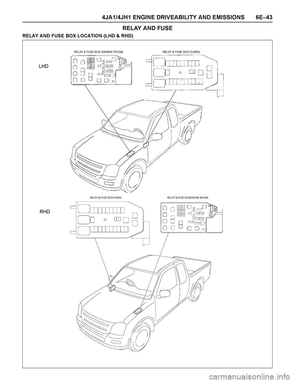
RELAY AND FUSE
RELAY A ND FUSE BOX LOCATION (LHD & RHD)
LHD
RHD
Page 1416 of 4264
6E–44 4JA1/4JH1 ENGINE DRIVEABILITY AND EMISSIONS
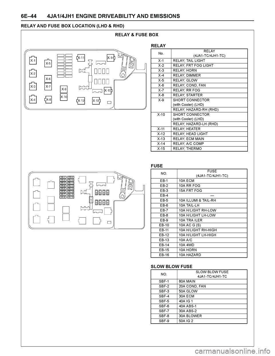
RELAY A ND FUSE BOX LOCATION (LHD & RHD)
RELAY & FUSE BOX
RELAY
No .RELAY
(4JA1-TC/4JH1-TC)
X -1 RELAY; TAIL LIGHT
X -2 RELAY; FRT F OG LI GHT
X -3 RELAY; HORN
X -4 RELAY; DIMMER
X -5 RELAY; GLOW
X -6 RELAY; COND, FAN
X -7 RELAY; RR FOG
X -8 RELAY; STARTER
X -9 SHORT CONNECTOR
(with Co oler) (LHD)
RELAY; HAZARD-RH (RHD)
X-10 SHORT CONNECTOR
(with Co oler) (LHD)
RELAY; HAZARD-LH (RHD)
X -11 RELAY; HEATER
X-12 RELAY; HEAD LIGHT
X-13 RELAY; ECM MAIN
X-14 RELAY; A/C COMP
X-15 RELAY; THERMO
FUSE
SLOW BLOW FUSE
NO.FUSE
(4JA1-TC/4JH1-TC)
EB-1 10A ECM
EB-2 10A RR FOG
EB-3 15A FRT FOG
EB-4 —
EB-5 10A ILLUMI & TAIL-RH
EB-6 10A TAIL-LH
EB-7 10A H/LIGHT RH-LOW
EB-8 10A H/LIGHT LH-LOW
EB-9 10A TRA ILER
EB-10 10A AC G (S)
EB-11 10A H/LIGHT RH-HIGH
EB-12 10A H/LIGHT LH-HIGH
EB-13 10A A/C
EB-14 10A 4WD
EB-15 10A HORN
EB-16 10A HAZARD
NO.SLOW BLOW FUSE
4JA1-TC/4JH1-TC
SBF-1 80A MAIN
SBF-2 20A COND, FAN
SBF-3 50A GLOW
SBF-4 30A ECM
SBF-5 40A IG 1
SBF-6 40A ABS-1
SBF-7 30A ABS-2
SBF-8 30A BLOWER
SBF-9 50A IG 2
Page 1417 of 4264
4JA1/4JH1 ENGINE DRIVEABILITY AND EMISSIONS 6E–45
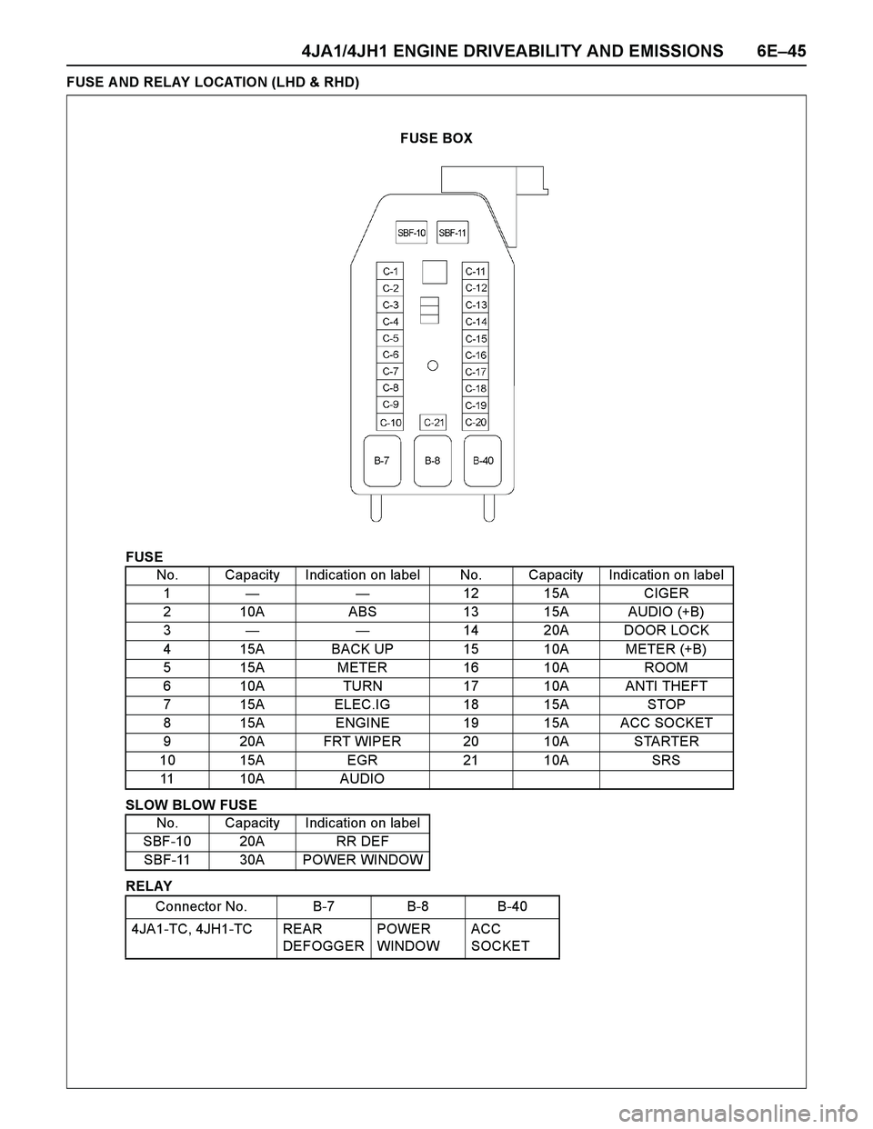
FUSE A ND RELAY LOCATION (LHD & RHD)
FUSE
SLOW BLOW FUSE
RELAYNo. Capacity Indication on label No. Capacity Indication on label
1——12 15A CIGER
2 10A ABS 13 15A AUDIO (+B)
3——14 20A DOOR LOCK
4 15A BACK UP 15 10A METER (+B)
5 15A METER 16 10A ROOM
6 10A TURN 17 10A ANTI THEFT
7 15A ELEC.IG 18 15A STOP
8 15A ENGINE 19 15A ACC SOCKET
9 20A FRT WIPER 20 10A STARTER
10 15A EGR 21 10A SRS
11 10A AUDIO
No. Capacity Indication on label
SBF-10 20A RR DEF
SBF-11 30A POWER WINDOW
Connector No. B-7 B-8 B-40
4JA1-TC, 4JH1-TC REAR
DEFOGGERPOWER
WINDOWACC
SOCKET
FUSE BOX
Page 1425 of 4264
4JA1/4JH1 ENGINE DRIVEABILITY AND EMISSIONS 6E–53
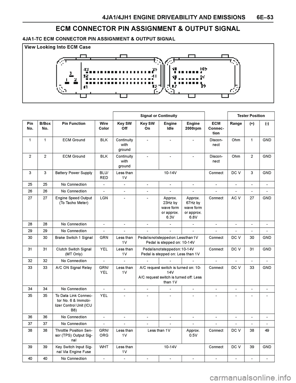
ECM CONNECTOR PIN ASSIGNMENT & OUTPUT SIGNAL
4JA1-TC ECM CONNECTOR PIN ASSIGNMENT & OUTPUT SIGNA L
View Looking Into ECM Case
Signal or Continuity Tester Position
Pin
No. B/Box
No.Pin Function Wire
ColorKey SW
OffKey SW
OnEngine
IdleEngine
2000rpmECM
Connec-
tionRange (+) (-)
1 1 ECM Gro und BLK Continuity
with
gro und---Discon-
ne ctOhm 1 GND
2 2 ECM Gro und BLK Continuity
with
gro und---Discon-
ne ctOhm 2 GND
3 3 Batte ry Powe r Supply BLU/
REDLess than
1V10-14V Connect DC V 3 GND
25 25 No Conne ctio n - - - - - - - - -
26 26 No Conne ctio n - - - - - - - - -
27 27 Engine Spee d Output
(To Ta cho Me te r)LGN - - Approx.
23Hz by
w a v e fo rm
or approx.
6.3V Approx.
67Hz by
wave form
or approx.
6.8V Co nnect AC V 27 GND
28 28 No Conne ctio n - - - - - - - - -
29 29 No Conne ctio n - - - - - - - - -
30 30 Brake Switch 1 Signal GRN Less than
1VPedal is not stepped on: Less than 1V
Pedal is stepped on: 10-14VCo nnect DC V 30 GND
31 31 Clutch Switch Signal
(MT Only )YEL Less than
1VPedal is not stepped on: 10-14V
Pedal is stepped on: Less than 1VCo nnect DC V 31 GND
32 32 No Conne ctio n - - - - - - - - -
33 33 A/C ON Signa l Re la y GRN/
YELLess than
1VA/C re que st switch is turne d on: 10-
14V
A/C request switch is turned off: Less
than 1VCo nnect DC V 33 GND
34 34 No Conne ctio n - - - - - - - - -
35 35 To Da ta Link Co nnec-
tor No. 6 & Immobi-
lize r Contro l Unit (ICU
B8)YEL--------
36 36 No Conne ctio n - - - - - - - - -
37 37 No Conne ctio n - - - - - - - - -
38 38 Throttle Po sitio n Sen-
so r (TPS) Output Sig-
na lGRN/
ORGLess than
1VLess than 1V Approx.
0.5VCo nnect DC V 38 49
39 39 Key Sw itch Input Sig-
nal Via Engine FuseWHT Less than
1V10-14V Co nnect DC V 39 GND
40 40 No Conne ctio n - - - - - - - - -
Page 1431 of 4264
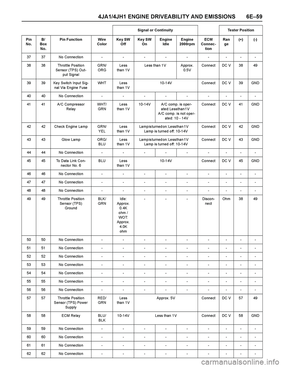
4JA1/4JH1 ENGINE DRIVEABILITY AND EMISSIONS 6E–59
3737No Connection---------
38 38 Throttle Po sitio n
Se nso r (TPS) Out-
put Signa lGRN/
ORGLe ss
tha n 1VLess than 1V Approx.
0.5VCo nnect DC V 38 49
39 39 Ke y Switch Input Sig-
nal Via Engine FuseWH T L e s s
tha n 1V10-14V Co nnect DC V 39 GND
4040No Connection---------
41 41 A/C Compressor
RelayWH T/
GRNLe ss
tha n 1V10-14V A/C comp. is o pe r-
ated: Less than 1V
A/C comp. is no t o pe r-
ate d: 10 - 14VCo nnect DC V 41 GND
42 42 Check Engine La mp GRN/
YELLe ss
tha n 1VLamp is turned on: Less than 1V
Lamp is turned off: 10-14VCo nnect DC V 42 GND
43 43 Glo w Lamp ORG/
BLULe ss
tha n 1VLamp is turned on: Less than 1V
Lamp is turned off: 10-14VCo nnect DC V 43 GND
4444No Connection---------
45 45 To Data Link Co n-
necto r No . 6BLU Less
tha n 1V10-14V Co nnect DC V 45 GND
4646No Connection---------
4747No Connection---------
4848No Connection---------
49 49 Throttle Po sitio n
Se nso r (TPS)
GroundBLK/
GRNIdle:
Appro x.
0.4K
ohm /
WO T:
Appro x.
4.0K
ohm---Discon-
ne ctOh m 3 8 4 9
5050No Connection---------
5151No Connection---------
5252No Connection---------
5353No Connection---------
5454No Connection---------
5555No Connection---------
5656No Connection---------
57 57 Throttle Po sitio n
Senso r (TPS) Po wer
SupplyRED/
GRNLe ss
tha n 1VApprox. 5V Connect DC V 57 49
58 58 ECM Re la y BLU/
BLK10-14V Less than 1V Connect DC V 58 GND
5959No Connection---------
6060No Connection---------
6161No Connection---------
6262No Connection---------Signal or Continuity Tester Position
Pin
No. B/
Box
No.Pin Function Wire
ColorKey SW
OffKey SW
OnEngine
IdleEngine
2000rpmECM
Connec-
tionRan
ge(+) (-)
Page 1439 of 4264
4JA1/4JH1 ENGINE DRIVEABILITY AND EMISSIONS 6E–67
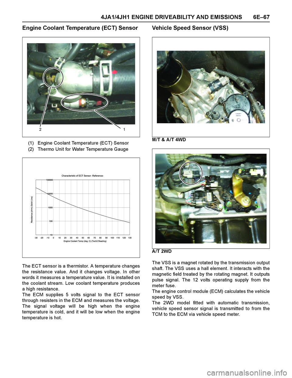
Engine Coolant Temperature (ECT) Sensor
The ECT sensor is a thermistor. A temperature changes
the resistance value. And it changes voltage. In other
words it measures a temperature value. It is installed on
the coolant stream. Low coolant temperature produces
a high resistance.
The ECM supplies 5 volts signal to the ECT sensor
through resisters in the ECM and measures the voltage.
The signal voltage will be high when the engine
temperature is cold, and it will be low when the engine
temperature is hot.
Vehicle Speed Sensor (VSS)
M/T & A /T 4WD
A/T 2WD
The VSS is a magnet rotated by the transmission output
shaft. The VSS uses a hall element. It interacts with the
magnetic field treated by the rotating magnet. It outputs
pulse signal. The 12 volts operating supply from the
meter fuse.
The engine control module (ECM) calculates the vehicle
speed by VSS.
The 2WD model fitted with automatic transmission,
vehicle speed sensor signal is transmitted to from the
TCM to the ECM via vehicle speed meter. (1) Engine Coolant Temperature (ECT) Sensor
(2) Thermo Unit for Water Temperature Gauge
12
Characteristic of ECT Sensor -Reference-
10 100 1000 10000 100000
-30 -20 -10 0 10 20 30 40 50 60 70 80 90 100 110 120 130
Engine Coolant Temp (deg. C) (Tech2 Reading)
Resistance (ohm) (Solid Line)
Page 1449 of 4264
4JA1/4JH1 ENGINE DRIVEABILITY AND EMISSIONS 6E–77
Diagnostic Thought Process
As you follow a diagnostic plan, every box on the
Strategy Based Diagnostics chart requires you to use
the diagnostic thought process. This method of thinking
optimizes your diagnosis in the following ways:
Improves your understanding and definition of the
customer complaint
Saves time by avoiding testing and/or replacing good
parts
Allows you to look at the problem from different
perspectives
Guides you to determine what level of understanding
about system operation is needed:
–Owner’s manual level
–Service manual level
–In-depth (engineering) level
–Owner’s manual level
–Service manual level
–In-depth (engineering) level
1. Verify the Complaint
What you should do
To verify the customer complaint, you need to know the
correct (normal) operating behavior of the system and
verify that the customer complaint is a valid failure of the
system.
The following information will help you verify the
complaint:
WHAT the vehicle model/options are
WHAT aftermarket and dealer-installed accessories
exist
WHAT related system(s) operate properly
WHEN the problem occurs
WHERE the problem occurs
HOW the problem occurs
HOW LONG the condition has ex isted (and if the
system ever worked correctly)
HOW OFTEN the problem occurs
Whether the severity of the problem has increased,
decreased or stayed the same
What resources you should use
Whenever possible, you should use the following
resources to assist you in verifying the complaint:
Service manual Theory or Circuit Description
sections
Service manual “System Performance Check”
Owner manual operational description
Technician ex perience
Identical vehicle for comparisonCircuit testing tools
Vehicle road tests
Complaint check sheet
Contact with the customer
2. Perform Preliminary Checks
NOTE: An estimated 10 percent of successful vehicle
repairs are diagnosed with this step!
What you should do
You perform preliminary checks for several reasons:
To detect if the cause of the complaint is VISUALLY
OBVIOUS
To identify parts of the system that work correctly
To accumulate enough data to correctly and
accurately search for a ISUZU Service Bulletin on
ISUZU Web site.
The initial checks may vary depending on the
complex ity of the system and may include the following
actions:
Operate the suspect system
Make a visual inspection of harness routing and
accessible/visible power and ground circuits
Check for blown fuses
Make a visual inspection for separated connectors
Make a visual inspection of connectors (includes
checking terminals for damage and tightness)
Check for any DTCs stored by the on-board
computers
Sense unusual noises, smells, vibrations or
mov ements
Investigate the vehicle service history (call other
dealerships, if appropriate)
What resources you should use
Whenever appropriate, you should use the following
resources for assistance in performing preliminary
checks:
Tech II or other technical equipment for viewing DTCs
Service manual information:
–Component locations
–Harness routing
–Wiring schematics
–Procedures for viewing DTCs
Dealership service history file
Vehicle road test
Identical vehicle or system for comparison
Page 1450 of 4264
6E–78 4JA1/4JH1 ENGINE DRIVEABILITY AND EMISSIONS
3. Check Bulletins and
Troubleshooting Hints
NOTE: As estimated 30 percent of successful vehicle
repairs are diagnosed with this step!
What you should do
You should have enough information gained from
preliminary checks to accurately search for a bulletin
and other related service information. Some service
manual sections provide troubleshooting hints that
match symptoms with specific complaints.
What resources you should use
You should use the following resources for assistance in
checking for bulletins and troubleshooting hints:
Printed bulletins
Access ISUZU Bulletin Web site.
Videotapes
Service manual
4. Perform Service Manual
Diagnostic Checks
What you should do
The “System Checks” in most service manual sections
and in most cells of section 8A (electrical) provide you
with:
A systematic approach to narrowing down the
possible causes of a system fault
Direction to specific diagnostic procedures in the
service manual
Assistance to identify what systems work correctly
What resources you should use
Whenever possible, you should use the following
resources to perform service manual checks:
Service manual
Technical equipment (for viewing DTCs and
analyzing data)
Digital multimeter and circuit testing tools
Other tools as needed
5a and 5b. Perform Service Manual
Diagnostic Procedures
NOTE: An estimated 40 percent of successful vehicle
repairs are diagnosed with these steps!
What you should do
When directed by service manual diagnostic checks,
you must then carefully and accurately perform the
steps of diagnostic procedures to locate the fault relatedto the customer complaint.
What resources you should use
Whenever appropriate, you should use the following
resources to perform service manual diagnostic
procedures:
Service manual
Technical equipment (for analyzing diagnostic data)
Digital multimeter and circuit testing tools
Essential and special tools
5c. Technician Self Diagnoses
When there is no DTC stored and no matching
symptom for the condition identified in the service
manual, you must begin with a thorough understanding
of how the system(s) operates. Efficient use of the
service manual combined with you ex perience and a
good process of elimination will result in accurate
diagnosis of the condition.
What you should do
Step 1: Identify and understand the suspect
circuit(s)
Having completed steps 1 through 4 of the Strategy
Based Diagnostics chart, you should have enough
information to identify the system(s) or sub-system(s)
involved. Using the service manual, you should
determine and investigate the following circuit
characteristics:
Electrical:
–How is the circuit powered (power distribution
charts and/or fuse block details)?
–How is the circuit grounded (ground distribution
charts)?
–How is the circuit controlled or sensed (theory of
operation):
–If it is a switched circuit, is it normally open or
normally closed?
–Is the power switched or is the ground
switched?
–Is it a variable resistance circuit (ECT sensor
or TP sensor, for ex ample)?
–Is it a signal generating device (MAF sensor of
VSS, for example)?
–Does it rely on some mechanical/vacuum
device to operate?
Physical:
–Where are the circuit components (component
locators and wire harness routing diagrams):
–Are there areas where wires could be chafed
or pinched (brackets or frames)?
–Are there areas subjected to ex treme
temperatures?