Page 1078 of 4264
8A-420 ELECTRICAL-BODY AND CHASSIS
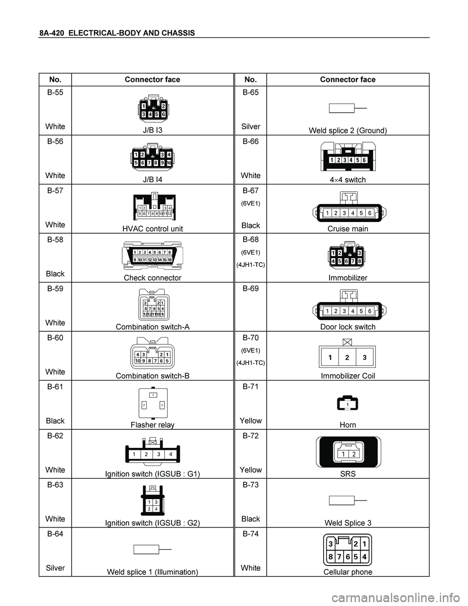
No. Connector face No. Connector face
B-55
White
J/B I3 B-65
SilverWeld splice 2 (Ground)
B-56
White
J/B I4 B-66
White4�4 switch
B-57
White
HVAC control unit B-67
(6VE1)
BlackCruise main
B-58
Black
Check connector B-68
(6VE1)
(4JH1-TC)
Immobilizer
B-59
White
Combination switch-A B-69
Door lock switch
B-60
White
Combination switch-B B-70
(6VE1)
(4JH1-TC)
Immobilizer Coil
B-61
Black
Flasher relay B-71
YellowHorn
B-62
White
Ignition switch (IGSUB : G1) B-72
YellowSRS
B-63
White
Ignition switch (IGSUB : G2) B-73
BlackWeld Splice 3
B-64
Silver
Weld splice 1 (Illumination) B-74
WhiteCellular phone
Page 1079 of 4264
ELECTRICAL-BODY AND CHASSIS 8A-421
No. Connector face No. Connector face
B-75
Black
Rear fog C/U
B-76
White
Front & rear fog light switch
B-77
(4JA1-L)
White Immobilizer C/U
B-78
White
Immobilizer antenna coil
B-79
White
Short connector (cooler only)
B-80
Black
Hazard relay (RH)
B-81
Black
Hazard relay (LH)
Page 1080 of 4264
8A-422 ELECTRICAL-BODY AND CHASSIS
No. Connector face No. Connector face
C-1
Gray
Side turn lamp-RH C-22
Front turn lamp-RH
C-2
Silver
Engine room-RH ground C-23
NOT USED
C-3
(6VE1)
(4JH1-TC)
INT Relay C-24
Triple pressure switch
C-4
Light-
blue
Front wiper motor C-25
NOT USED
C-5
~
C-16 NOT USED C-26
Black
Head lamp-LH
C-17
Gray
Front wiper motor C-27
Clearance lamp-LH
C-18
Clearance lamp-RH C-28
~
C-29 NOT USED
C-19
Black
Head lamp-RH C-30
BlackEngine hood switch
C-20
(6VE1)
(4JH1-TC)
Horn ; high note C-31
~
C-34 NOT USED
C-21
Black
Horn ; Low note C-35
Gray Side turn lamp-LH
Page 1095 of 4264
ELECTRICAL-BODY AND CHASSIS 8A-437
No. Connector face No. Connector face
P-1
Silver
Battery (+) P-9
SilverACG (B)
P-2
Silver
Relay & Fuse box P-10
SilverEngine ground
P-3
Brown
Starter (S) P-11
SilverFuse & relay box
P-4
Silver
Starter (B) P-12
NOT USED
P-4
Silver
Starter (B) P-13
Gray Shift on the fly actuator
P-5
Silver
Battery (-) P-14
WhiteFuse & relay box
P-6
Silver
Body earth (Ground) P-15
Silver2nd battery (+)
P-7
NOT USED P-16
Silver
2nd battey (-)
P-8
(C24SE)
(4JH1-TC
Green ACG (L)
P-8
(6VE1)
White ACG (L)
Page 1098 of 4264
8A-440 ELECTRICAL-BODY AND CHASSIS
No. Connector face No. Connector face
X-1
Black
Relay ; Tail lamp X-8
(4JH1-TC)
BlackRelay ; Starter
X-2
(C24SE)
(6VE1)
Black Relay ; Front Fog lamp X-9
(6VE1)
(4JH1-TC)
BlackRelay ; Hazard-RH
X-2
(4JH1-TC)
Black Relay ; Front Fog lamp X-10
(6VE1)
(4JH1-TC)
BlackRelay ; Hazard-LH
X-3
Relay ; Horn X-11
BlackRelay ; Heater
X-4
Relay ; Dimmer X-12
BlackRelay ; Head lamp
X-5
(6VE1)
Black Relay ; Front Fog Lamp X-13
(6VE1)
(4JH1-TC)
BlackRelay ; ECM MAIN
X-5
(4JH1-TC)
Black Relay ; Spill valve X-14
BlackRelay ; A/C Compressor
X-6
(C24SE)
(6VE1)
Relay ; Starter X-15
BlackRelay ; Thermo
X-6
(4JA1-L)
Black Relay ; CSD X-16
(6VE1)
(4JH1-TC)
BlackDIODE
X-7
Relay ; Condenser Fan X-17
BlackDIODE
Page 1123 of 4264

TROUBLESHOOTING 6 – 3
1. Hard Starting
Inspect the following items before diagnosis.
1. The battery conditions.
The terminal connection condition.
The battery charge condition or battery power weakness.
2. The fan belt loosen or broken.
3. The main fuse condition (open or not).
4. Fuel quantity level.
1–1 Starter motor inoperative
Step Action Value(s) Yes No
1 Check the starter switch.
Does the starter switch work? —
Go to Step 2 Repair or
replace the
starter switch
2 Check the starter relay.
Does the starter relay work? —
Go to Step 3 Repair or
replace the
starter relay
3 Check the magnetic switch.
Does the magnetic switch work? —
Go to Step 4 Repair or
replace the
magnetic
switch
4 Check the pinion gear condition on the starter motor.
Was the condition normal? —
Go to Step 5 Replace the
pinion gear
5 Check the brush wear or brush spring weakness.
Was the condition normal? —
Replace the
starter motor
assembly Repair or
replace the
brush or brush
spring
1-2 Starter motor operates but engine does not turn over
Step Action Value(s) Yes No
1 Check the engine internal seizure.
Was the engine seized? —
Repair or
replace seized
parts Check other
DTC by Tech
2 and go to
indicated DTC
Page 1339 of 4264

ENGINE ELECTRICAL 6D – 1
SECTION 6D
ENGINE ELECTRICAL
TABLE OF CONTENTS
PAGE
Main Data and Specifications ......................................................................................... 6D - 2
General Description......................................................................................................... 6D - 3
Torque Specifications ..................................................................................................... 6D - 5
Generator.......................................................................................................................... 6D - 7
Removal and Installation ............................................................................................ 6D - 7
Disassembly................................................................................................................. 6D - 9
Inspection and Repair ................................................................................................. 6D - 12
Reassembly.................................................................................................................. 6D - 18
Starter Motor .................................................................................................................... 6D - 22
Removal and Installation ............................................................................................ 6D - 22
Disassembly................................................................................................................. 6D - 23
Inspection and Repair ................................................................................................. 6D - 26
Reassembly.................................................................................................................. 6D - 29
Pre-heating System ......................................................................................................... 6D -33
Inspection and Repair ................................................................................................. 6D -33
Glow Relay ................................................................................................................... 6D -33
Glow Plug ..................................................................................................................... 6D -33
EGR System ................................................................................................................. 6D -33
Page 1371 of 4264
ENGINE ELECTRICAL 6D – 33
PRE-HEATING SYSTEM
INSPECTION AND REPAIR
Make the necessary adjustments, repairs, and part replacement if excessive wear of damage is discovered during
inspection.
VISUAL CHECK
Check the main fuses and glow indicator for damage.
Replace the part(s) if required.
GLOW RELAY
The glow relay is located in the relay box the engine
compartment.
825R300046
Use an ohmmeter to measure the resistance between
terminals No.2 and No.3.
If the measured value is outside the specified range, the
glow relay must be replaced.
Glow Relay Resistance Ohms
94 � 114
GLOW PLUG
LNW21KSH001401
Use a circuit tester to test the glow plugs for continuity.
Glow Plug Resistance (Reference) Ohms
Approximately 0.9
EGR SYSTEM 4JA1T (L)
Refer to 6F-9. (EGR system diagram)

White Immobilizer C/")

 P-9
SilverACG (B)
P-2
Silver
Relay & Fuse box P-10
SilverEngine ground
P-3
Brown")

BlackRelay ; Starter
X-2
(C24SE)
(6VE1)
Black Relay ; Front Fog lamp")
