Page 3999 of 4264
DIAGNOSIS (JR405E) 7A2-7
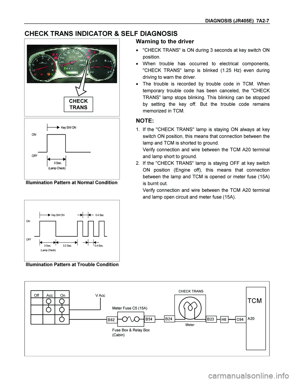
CHECK TRANS INDICATOR & SELF DIAGNOSIS
CHECK
TRANS
Warning to the driver
� "CHECK TRANS" is ON during 3 seconds at key switch ON
position.
� When trouble has occurred to electrical components,
"CHECK TRANS" lamp is blinked (1.25 Hz) even during
driving to warn the driver.
� The trouble is recorded by trouble code in TCM. When
temporary trouble code has been canceled, the "CHEC
K
TRANS" lamp stops blinking. This blinking can be stopped
by setting the key off. But the trouble code remains
memorized in TCM.
��������Key SW ON
ON
OFF
��
3 Sec.
(Lamp Check)
Illumination Pattern at Normal Condition
NOTE:
1. If the "CHECK TRANS" lamp is staying ON always at key
switch ON position, this means that connection between the
lamp and TCM is shorted to ground.
Verify connection and wire between the TCM A20 terminal
and lamp short to ground.
2. If the "CHECK TRANS" lamp is staying OFF at key switch
ON position (Engine off), this means that connection
between the lamp and TCM is opened or meter fuse (15A)
is burnt out.
Verify connection and wire between the TCM A20 terminal
and lamp open circuit and meter fuse (15A).
��������
Key SW ON 0.4 Sec.
ON
OFF
3 Sec.����
3.2 Sec.����
�
0.4 Sec.
(Lamp Check)
Illumination Pattern at Trouble Condition
Off Acc On V Acc
CHECK TRANS
Meter
Meter Fuse C5 (15A)
Fuse Box & Relay Box
(Cabin)
�
�� �
TCM
������������� ��
��
Page 4024 of 4264
7A2-32 DIAGNOSIS (JR405E)
No. Connector face No. Connector face
E-30
(4JH1-TC)
Gray A/T speed sensor H-23
(6VE1)
(4JH1-TC)
WhiteEngine ~ Engine room B
E-31
(4JH1-TC)
Gray Turbine sensor P-1
SilverBattery (+)
E-44
Gray
Vehicle speed sensor P-2
SilverRelay & Fuse box
E-51
(4JH1-TC)
Black Inhibiter switch P-5
SilverBattery (-)
E-54
(4JH1-TC)
Black A/T term ASM P-6
SilverBody earth (Ground)
H-4
(6VE1)
(4JH1-TC)
White Engine ~ Engine room P-10
SilverEngine ground
H-6
White
Engine room ~ INST R-15
Black2-4 WD control unit
H-7
White
Engine room ~ INST
H-18
(RHD)
White Engine room ~ INST
H-22
(6VE1)
(4JH1-TC)
White Engine ~ Engine room C
Page 4036 of 4264
7A2-44 DIAGNOSIS (JR405E)
DTC P0705 (Flash Code 17) Inhibitor Switch Failure
Inhibitor SW
TCM
A2 (P)
A17 (3)
B2 (2)
B10 (N)
B11 (D)
B19 (R)
B21 (L)
C95 (2)
(10)
(11)
(19)
(21)
YEL/VIO
RED/BLK
BLU BLK/GRN
Starter Relay
C94 (2)
(3)
BH22 (1)
(6)
(4)
(7)
(5)
(2)
P
2
R
N
D
3
L
Start SW
PNK/BLU
E51
(2)
(4)
(8)
(5)
(1)
(9)
(6)
(3)
(10)
(7)
(38)
(15) (3)
(37) H4 PNK/BLK
RED/YEL
YEL/VIO
BLK/GRN
PNK/BLK
RED/BLK
BLU
RED/YEL
PNK/BLU
BLK/WHT
BLK BLK
BLK/WHT Key Switch
WHT
WHT
ICU (W/ Immobiliser)
Ground (W/O Immobiliser)
Terminal Assembly Inhibitor Switch
Page 4090 of 4264
7A2-98 DIAGNOSIS (JR405E)
Step Action Yes No
4 Are the quantity, contamination and smell normal?
If the ATF level is
low, replenish up to
the specified level.
Go to Step 5
If ATF is extremely
black and
contaminated and
smells burnt, slip of
the clutch is
supposed.
Overhaul the AT
unit.
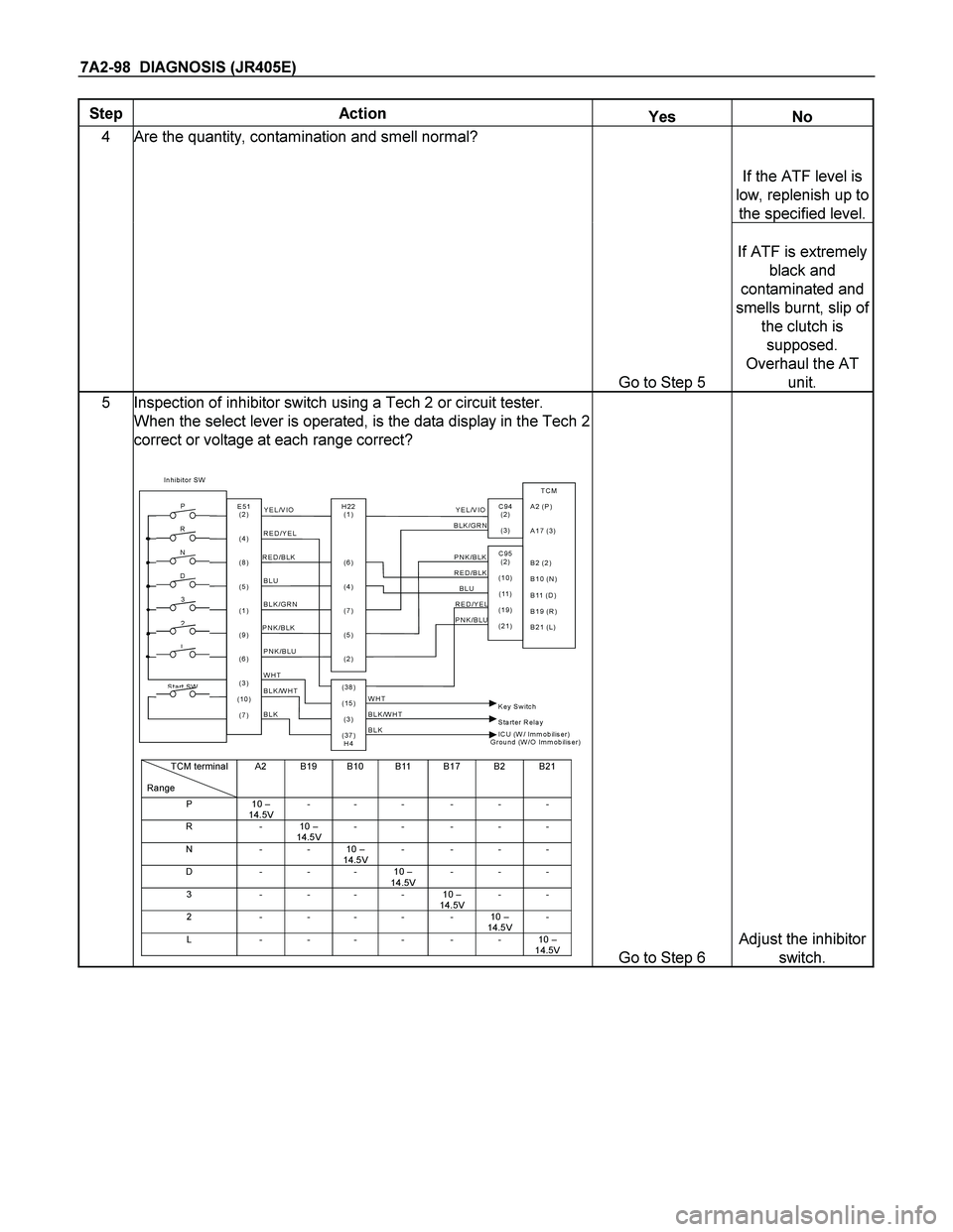
5 Inspection of inhibitor switch using a Tech 2 or circuit tester.
When the select lever is operated, is the data display in the Tech 2
correct or voltage at each range correct?
Inhibitor SW
TCM
A2 (P)
A17 (3)
B2 (2)
B10 (N)
B11 (D)
B19 (R)
B21 (L)
C95
(2 )
(10)
(11 )
(19)
(21) Y E L /V IO
RED/BLK
BLUBLK/GRN
Starter Relay
C94
(2 )
(3 )
BH22
(1)
(6)
(4)
(7)
(5)
(2) P
2
R
N
D
3
L
Start SW
PNK/BLU
E51
(2)
(4)
(8)
(5)
(1)
(9)
(6)
(3)
(10)
(7)
(38)
(15)
(3)
(37)
H4PNK/BLK
RED/YEL Y E L /V IO
BLK/GRN
PNK/BLK RED/BLK
BLU RED/YEL
PNK/BLU
BLK/WHT
BLK
BLK BLK/WHT Key Switch WHT
WHT
ICU (W/ Immobilis e r)
Ground (W/O Immobilis e r)
TCM terminal
RangeA2 B19 B10 B11 B17 B2 B21
P10 –
14.5V-- - - - -
R-10 –
14.5V-- ---
N--10 –
14.5V----
D - - - 10 –
14.5V---
3----10 –
14.5V--
2-----10 –
14.5V-
L------10 –
14.5V
Go to Step 6
Adjust the inhibitor
switch.
Page 4110 of 4264
7A2-118 DIAGNOSIS (JR405E)
Step Action Yes No
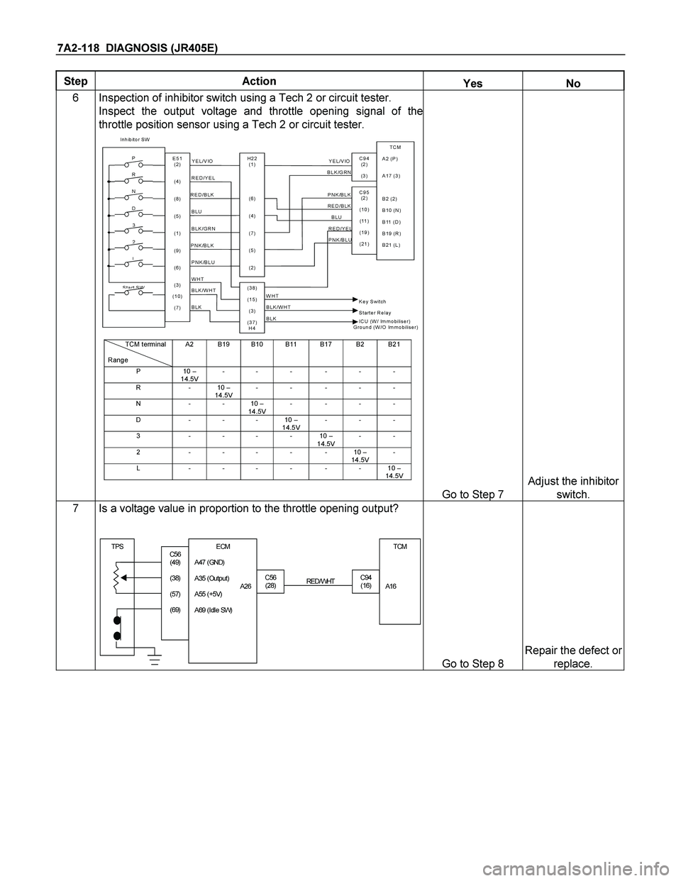
6 Inspection of inhibitor switch using a Tech 2 or circuit tester.
Inspect the output voltage and throttle opening signal of the
throttle position sensor using a Tech 2 or circuit tester.
Inhibitor SW
TCM
A2 (P)
A17 (3)
B2 (2)
B10 (N)
B11 (D)
B19 (R)
B21 (L)
C95
(2 )
(10)
(11 )
(19)
(21) Y E L /V IO
RED/BLK
BLUBLK/GRN
Starter Relay
C94
(2 )
(3 )
BH22
(1)
(6)
(4)
(7)
(5)
(2) P
2
R
N
D
3
L
Start SW
PNK/BLU
E51
(2)
(4)
(8)
(5)
(1)
(9)
(6)
(3)
(10)
(7)
(38)
(15)
(3)
(37)
H4PNK/BLK
RED/YEL Y E L /V IO
BLK/GRN
PNK/BLK RED/BLK
BLU RED/YEL
PNK/BLU
BLK/WHT
BLK
BLK BLK/WHT Key Switch WHT
WHT
ICU (W/ Immobilis e r)
Ground (W/O Immobilis e r)
TCM terminal
RangeA2 B19 B10 B11 B17 B2 B21
P10 –
14.5V-- - - - -
R-10 –
14.5V-- ---
N--10 –
14.5V----
D - - - 10 –
14.5V---
3----10 –
14.5V--
2-----10 –
14.5V-
L------10 –
14.5V
Go to Step 7
Adjust the inhibitor
switch.
7 Is a voltage value in proportion to the throttle opening output?
TPSTCM
A16
C56
(28)C94
(16) RED/ WHT
C56
(49)
(38)
(57)
(69)ECM
A47 (GND)
A35 (Out put )
A26
A55 (+5V)
A69 (I dl e SW)
Go to Step 8
Repair the defect or
replace.
Page 4114 of 4264
7A2-122 DIAGNOSIS (JR405E)
Step Action Yes No
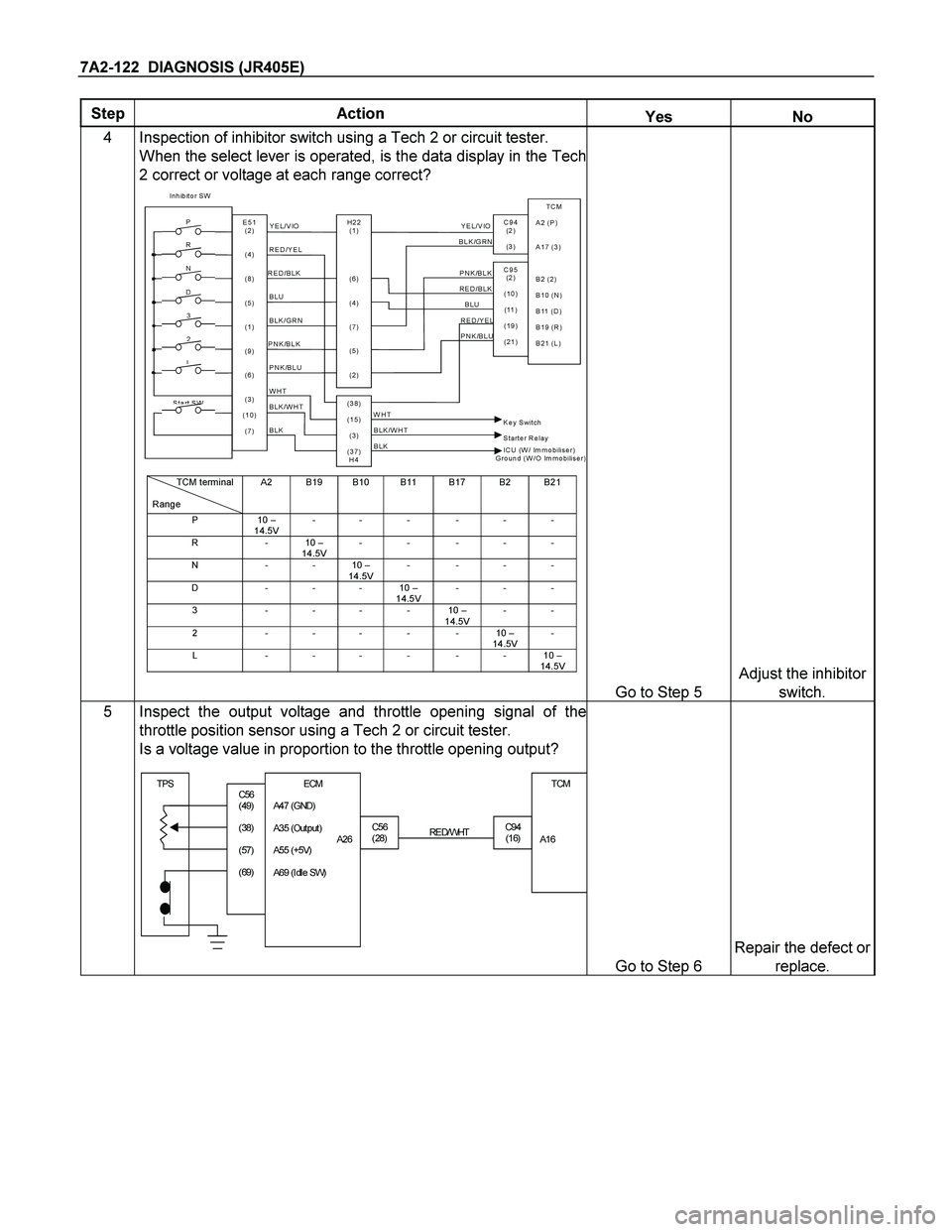
4 Inspection of inhibitor switch using a Tech 2 or circuit tester.
When the select lever is operated, is the data display in the Tech
2 correct or voltage at each range correct?
Inhibitor SW
TCM
A2 (P)
A17 (3)
B2 (2)
B10 (N)
B11 (D)
B19 (R)
B21 (L)
C95
(2 )
(10)
(11 )
(19)
(21) Y E L /V IO
RED/BLK
BLUBLK/GRN
Starter Relay
C94
(2 )
(3 )
BH22
(1)
(6)
(4)
(7)
(5)
(2) P
2
R
N
D
3
L
Start SW
PNK/BLU
E51
(2)
(4)
(8)
(5)
(1)
(9)
(6)
(3)
(10)
(7)
(38)
(15)
(3)
(37)
H4PNK/BLK
RED/YEL Y E L /V IO
BLK/GRN
PNK/BLK RED/BLK
BLU RED/YEL
PNK/BLU
BLK/WHT
BLK
BLK BLK/WHT Key Switch WHT
WHT
ICU (W/ Immobilis e r)
Ground (W/O Immobilis e r)
TCM terminal
RangeA2 B19 B10 B11 B17 B2 B21
P10 –
14.5V-- - - - -
R-10 –
14.5V-- ---
N--10 –
14.5V----
D - - - 10 –
14.5V---
3----10 –
14.5V--
2-----10 –
14.5V-
L------10 –
14.5V
Go to Step 5
Adjust the inhibitor
switch.
5 Inspect the output voltage and throttle opening signal of the
throttle position sensor using a Tech 2 or circuit tester.
Is a voltage value in proportion to the throttle opening output?
TPSTCM
A16
C56
(28)C94
(16) RED/ WHT
C56
(49)
(38)
(57)
(69)ECM
A47 (GND)
A35 (Out put )
A26
A55 (+5V)
A69 (I dl e SW)
Go to Step 6
Repair the defect or
replace.
Page 4117 of 4264
DIAGNOSIS (JR405E) 7A2-125
Step Action Yes No
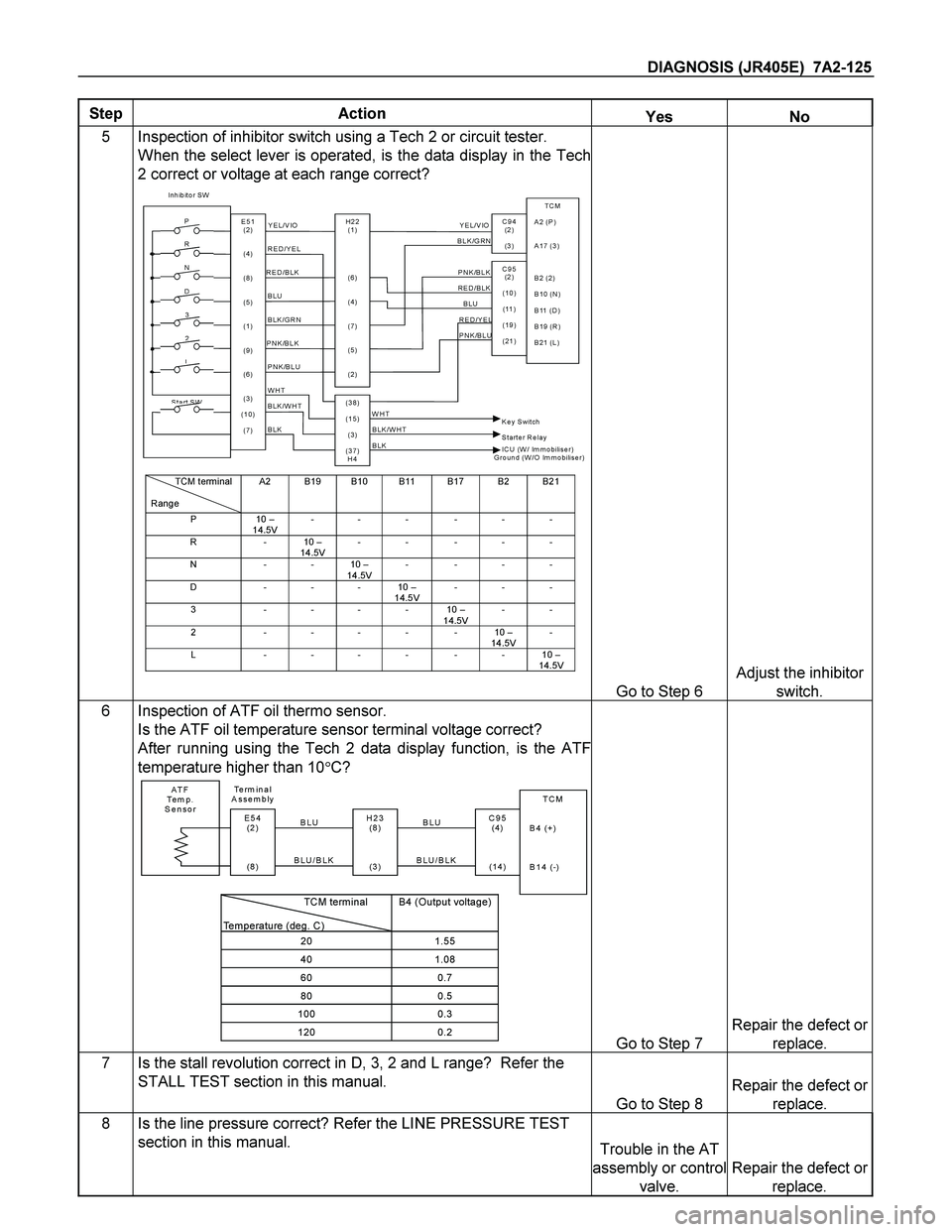
5 Inspection of inhibitor switch using a Tech 2 or circuit tester.
When the select lever is operated, is the data display in the Tech
2 correct or voltage at each range correct?
Inhibitor SW
TCM
A2 (P)
A17 (3)
B2 (2)
B10 (N)
B11 (D)
B19 (R)
B21 (L)
C95
(2 )
(10)
(11 )
(19)
(21) Y E L /V IO
RED/BLK
BLUBLK/GRN
Starter Relay
C94
(2 )
(3 )
BH22
(1)
(6)
(4)
(7)
(5)
(2) P
2
R
N
D
3
L
Start SW
PNK/BLU
E51
(2)
(4)
(8)
(5)
(1)
(9)
(6)
(3)
(10)
(7)
(38)
(15)
(3)
(37)
H4PNK/BLK
RED/YEL Y E L /V IO
BLK/GRN
PNK/BLK RED/BLK
BLU RED/YEL
PNK/BLU
BLK/WHT
BLK
BLK BLK/WHT Key Switch WHT
WHT
ICU (W/ Immobilis e r)
Ground (W/O Immobilis e r)
TCM terminal
RangeA2 B19 B10 B11 B17 B2 B21
P10 –
14.5V-- - - - -
R-10 –
14.5V-- ---
N--10 –
14.5V----
D - - - 10 –
14.5V---
3----10 –
14.5V--
2-----10 –
14.5V-
L------10 –
14.5V
Go to Step 6
Adjust the inhibitor
switch.
6 Inspection of ATF oil thermo sensor.
Is the ATF oil temperature sensor terminal voltage correct?
After running using the Tech 2 data display function, is the ATF
temperature higher than 10�C?
ATF
Te m p .
SensorTCM
B4 (+)
B14 (-)
H23
(8 )
(3 )C95
(4)
(14) BLU Te rm i n a l
Assembly
BLU/BLKE54
(2 )
(8 ) BLU
BLU/BLK
TCM terminal
Temperature (deg. C)
B4 (Output voltage)
201.55
401.08
600.7
800.5
1000.3
1200.2Go to Step 7
Repair the defect or
replace.
7 Is the stall revolution correct in D, 3, 2 and L range? Refer the
STALL TEST section in this manual.
Go to Step 8
Repair the defect or
replace.
8 Is the line pressure correct? Refer the LINE PRESSURE TEST
section in this manual. Trouble in the AT
assembly or control
valve.
Repair the defect or
replace.
Page 4120 of 4264
7A2-128 DIAGNOSIS (JR405E)
Step Action Yes No
4 Are the quantity, contamination and smell normal?
If the ATF level is
low, replenish up to
the specified level.
Go to Step 5
If ATF is extremely
black and
contaminated and
smells burnt, slip of
the clutch is
supposed.
Overhaul the AT
unit.
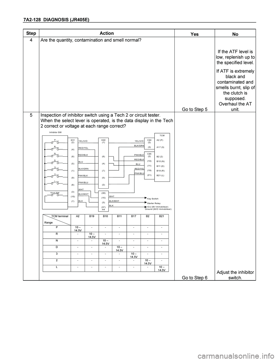
5 Inspection of inhibitor switch using a Tech 2 or circuit tester.
When the select lever is operated, is the data display in the Tech
2 correct or voltage at each range correct?
Inhibitor SW
TCM
A2 (P)
A17 (3)
B2 (2)
B10 (N)
B11 (D)
B19 (R)
B21 (L)
C95
(2 )
(10)
(11 )
(19)
(21) Y E L /V IO
RED/BLK
BLUBLK/GRN
Starter Relay
C94
(2 )
(3 )
BH22
(1)
(6)
(4)
(7)
(5)
(2) P
2
R
N
D
3
L
Start SW
PNK/BLU
E51
(2)
(4)
(8)
(5)
(1)
(9)
(6)
(3)
(10)
(7)
(38)
(15)
(3)
(37)
H4PNK/BLK
RED/YEL Y E L /V IO
BLK/GRN
PNK/BLK RED/BLK
BLU RED/YEL
PNK/BLU
BLK/WHT
BLK
BLK BLK/WHT Key Switch WHT
WHT
ICU (W/ Immobilis e r)
Ground (W/O Immobilis e r)
TCM terminal
RangeA2 B19 B10 B11 B17 B2 B21
P10 –
14.5V-- - - - -
R-10 –
14.5V-- ---
N--10 –
14.5V----
D - - - 10 –
14.5V---
3----10 –
14.5V--
2-----10 –
14.5V-
L------10 –
14.5V
Go to Step 6
Adjust the inhibitor
switch.