Page 3666 of 4264
7D1-40 TRANSFER CONTROL SYSTEM
Memory erasing procedure
1. Prepare two pieces of short harness with the end sharped
like a needle (bout 20cm(7.9 in) long).
2. Turn OFF the ignition.
3. Remove the front left seat ASM.
4. Make the controller under the front left seat ASM (spread
the cut of the floor carpet).
5. Keeping the connector of the transfer controller connected,
set the short harness from the back of the connector as
illustrated.
6. Turn ON the ignition, wait for 2 seconds, and turn OFF the
ignition after confirming the relay sound.
7. Disconnect the short harness, turn ON the ignition again,
and confirm the “Check 4WD” lamp in the meter panel is
OFF.
8. Before erasing the memory, check that the circuit of the T/F
actuator position detection harness, etc. for it are normal.
Transfer Controller Pin Assignment
RTW47DSF000101
Page 3668 of 4264

7D1-42 TRANSFER CONTROL SYSTEM
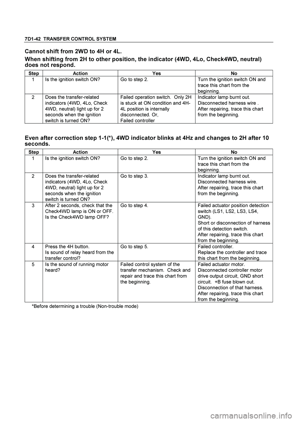
Cannot shift from 2WD to 4H or 4L.
When shifting from 2H to other position, the indicator (4WD, 4Lo, Check4WD, neutral)
does not respond.
Step Action Yes No
1 Is the ignition switch ON? Go to step 2. Turn the ignition switch ON and
trace this chart from the
beginning.
2 Does the transfer-related
indicators (4WD, 4Lo, Check
4WD, neutral) light up for 2
seconds when the ignition
switch is turned ON? Failed operation switch. Only 2H
is stuck at ON condition and 4H-
4L position is internally
disconnected. Or,
Failed controller Indicator lamp burnt out.
Disconnected harness wire .
After repairing, trace this chart
from the beginning.
Even after correction step 1-1(*), 4WD indicator blinks at 4Hz and changes to 2H after 10
seconds.
Step Action Yes No
1 Is the ignition switch ON? Go to step 2. Turn the ignition switch ON and
trace this chart from the
beginning.
2 Does the transfer-related
indicators (4WD, 4Lo, Check
4WD, neutral) light up for 2
seconds when the ignition
switch is turned ON? Go to step 3. Indicator lamp burnt out.
Disconnected harness wire.
After repairing, trace this chart
from the beginning.
3 After 2 seconds, check that the
Check4WD lamp is ON or OFF.
Is the Check4WD lamp OFF? Go to step 4. Failed actuator position detection
switch (LS1, LS2, LS3, LS4,
GND).
Short or disconnection of harness
of this detection switch.
After repairing, trace this chart
from the beginning.
4 Press the 4H button.
Is sound of relay heard from the
transfer control? Go to step 5. Failed controller.
Replace the controller and trace
this chart from the beginning.
5 Is the sound of running motor
heard? Failed control system of the
transfer mechanism. Check and
repair and trace this chart from
the beginning. Failed actuator motor.
Disconnected controller motor
drive output circuit, GND short
circuit. +B fuse blown out.
Disconnection of that harness.
After repairing, trace this chart
from the beginning.
*Before determining a trouble (Non-trouble mode)
Page 3670 of 4264
7D1-44 TRANSFER CONTROL SYSTEM
After operation, indicator of target position blinks for 1.5 sec. at 2Hz, return to 2H
condition (4WD indicator going out)
Step Action Yes No
1 Keep to press the 4H button
(about 10 seconds).
Does the 4WD indicator blink at
2Hz for 15 seconds and then
blink at 4Hz? Failed actuator motor.
Disconnection of controller motor
drive output circuit, or GND short.
+B fuse blown out.
Disconnection of that harness.
After repairing, trace this chart
from the beginning. Go to step 2.
2 Press the 4H button.
Is the sound of relay heard from
the transfer controller? Go to step 3. Failed controller.
Replace the controller and trace
this chart from the beginning.
3 Is the sound of running motor
heart? Failed control system of the
transfer mechanism. Check and
repair and trace this chart from
the beginning. Failed actuator motor.
Disconnection or GND short of
controller motor drive output
circuit.
After repairing, trace this chart
from the beginning.
Page 3671 of 4264

TRANSFER CONTROL SYSTEM 7D1-45
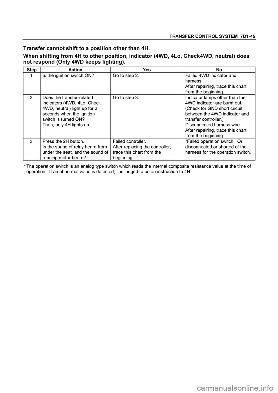
Transfer cannot shift to a position other than 4H.
When shifting from 4H to other position, indicator (4WD, 4Lo, Check4WD, neutral) does
not respond (Only 4WD keeps lighting).
Step Action Yes No
1 Is the ignition switch ON? Go to step 2. Failed 4WD indicator and
harness.
After repairing, trace this chart
from the beginning.
2 Does the transfer-related
indicators (4WD, 4Lo, Check
4WD, neutral) light up for 2
seconds when the ignition
switch is turned ON?
Then, only 4H lights up. Go to step 3. Indicator lamps other than the
4WD indicator are burnt out.
(Check for GND short circuit
between the 4WD indicator and
transfer controller.)
Disconnected harness wire.
After repairing, trace this chart
from the beginning.
3 Press the 2H button.
Is the sound of relay heard from
under the seat, and the sound of
running motor heard? Failed controller.
After replacing the controller,
trace this chart from the
beginning. *Failed operation switch. Or
disconnected or shorted of the
harness for the operation switch.
* The operation switch is an analog type switch which reads the internal composite resistance value at the time of
operation. If an abnormal value is detected, it is judged to be an instruction to 4H.
Page 3673 of 4264

TRANSFER CONTROL SYSTEM 7D1-47
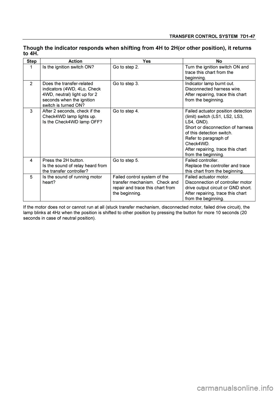
Though the indicator responds when shifting from 4H to 2H(or other position), it returns
to 4H.
Step Action Yes No
1 Is the ignition switch ON? Go to step 2. Turn the ignition switch ON and
trace this chart from the
beginning.
2 Does the transfer-related
indicators (4WD, 4Lo, Check
4WD, neutral) light up for 2
seconds when the ignition
switch is turned ON? Go to step 3. Indicator lamp burnt out.
Disconnected harness wire.
After repairing, trace this chart
from the beginning.
3 After 2 seconds, check if the
Check4WD lamp lights up.
Is the Check4WD lamp OFF? Go to step 4. Failed actuator position detection
(limit) switch (LS1, LS2, LS3,
LS4, GND).
Short or disconnection of harness
of this detection switch.
Refer to paragraph of
Check4WD.
After repairing, trace this chart
from the beginning.
4 Press the 2H button.
Is the sound of relay heard from
the transfer controller? Go to step 5. Failed controller.
Replace the controller and trace
this chart from the beginning.
5 Is the sound of running motor
heart? Failed control system of the
transfer mechanism. Check and
repair and trace this chart from
the beginning. Failed actuator motor.
Disconnection of controller motor
drive output circuit or GND short.
After repairing, trace this chart
from the beginning.
If the motor does not or cannot run at all (stuck transfer mechanism, disconnected motor, failed drive circuit), the
lamp blinks at 4Hz when the position is shifted to other position by pressing the button for more 10 seconds (20
seconds in case of neutral position).
Page 3918 of 4264
7A4–110 UNIT REPAIR (AW30–40LE)
Disassembled View
2 43R20 0074
E nd O FCallo ut
Legend
(1) Check ball
(2) Retainer
(3) Check valve NO.2
(4) Ball
(5) Check valve NO.1
(6) Retainer
(7) Check valve NO.2
(8) Ball
(9) Check valve NO.1
(10) Retainer
(11) Plug
(12) Secondary regulator valve
(13) Spring
(14) Retainer
(15) Plug
(16) Spring
(17) 2–3 shift valve(18) Retainer
(19) Plug
(20) Spring
(21) Reverse control valve
(22) Retainer
(23) Plug
(24) Second coast modulator valve
(25) Spring
(26) Retainer
(27) Plug
(28) 3–4 shift valve
(29) Spring
(30) Retainer
(31) Sleeve
(32) Plunger
(33) Spring
(34) Lock-up relay valve
(35) Upper valve body
Page 3923 of 4264
UNIT REPAIR (AW30–40LE) 7A4–11 5
16. Remove the retainer (30) for lock-up relay valve with
a magnetic finger by pushing in the sleeve.
2 43R20 007 1
17. Remove the sleeve(31) with the plunger(32),
spring(33) and lock-up relay valve(34).
Remove the lock-up relay valve(34), spring(33) and
plunger(32) from the sleeve(31).
2 43R20 006 5
Inspection and Repair
1. Inspect valve springs
Check for damage, squareness, rust and distorted
coils.
Measure the spring free length and replace if less
than below.
mm (in)
2 43R20 0076
SpringFree
lengthColor
(1) Secondary regulator valve32.9
(1.295)PURPLE
(2) 2–3 shift valve30.8
(1.213)PURPLE
(3) Reverse control valve25.6
(1.008)—
(4) Second coast modulator
valve25.3
(0.996)ORANGE
(5) 3–4 shift valve30.8
(1.213)PURPLE
(6) Lock-up relay valve 23.4
(0.912)RED
Page 3924 of 4264
7A4–116 UNIT REPAIR (AW30–40LE)
Reassembly
1. Install the plunger(32) and spring(33) into the
sleeve(31).
Install the lock-up relay valve(34) into the
sleeve(31).
Install the sleeve(31) with the plunger(32),
spring(33) and lock-up relay valve(34) into the bore.
2 43R20 006 5
2. Install the retainer(30).
2 43R20 007 1
3. Install the spring, 3-4 shift valve(28) and plug(27)
into the bore.
2 43R20 0064
4. Install the retainer(26) by pushing the plug.
2 43R20 0072