Page 2682 of 4264

6E–106 ENGINE DRIVEABILITY AND EMISSIONS
10 Repair the open circuit between the fuel pump relay
and battery.
Is the action complete?—Veri fy repai r—
11 Using the DVM and check the fuel pump power supply
circuit.
1. Ignition “On”, engine “Off”.
2. Disconnect the fuel pump connector.
3. Check the circuit for open or short to ground
circuit.
Was the DVM indicated specified value?
10 - 14.5V Go to Step 13Go to Step 12
12 Repair the open or short to ground circuit between the
fuel pump relay and fuel pump.
Is the action complete?—Veri fy repai r—
13 Using the DVM and check the fuel pump ground
circuit.
1. Ignition “Off”, engine “Off”.
2. Disconnect the fuel pump connector.
3. Check the circuit for open circuit.
Was the DVM indicated specified value?
Continuity Go to Step 15Go to Step 14
14 Repair the open circuit between the fuel pump and
body ground.
Is the action complete?—Veri fy repai r—
15 Replace the fuel pump.
Was the problem solved?—Verify repair Go to Step 16
16 Is the ECM programmed with the latest software
release?
If not, download the latest software to the ECM using
the “SPS (Service Programming System)”.
Was the problem solved?—Verify repair Go to Step 17 Step Action Value(s) Yes No
V
1
F2
F-2
�
�
Page 2685 of 4264
.
4. Fuel pressure that drops off during acceleration,
cruise, or hard cornering may case a lean condition.
A lean condition can cause a")
ENGINE DRIVEABILITY AND EMISSIONS 6E–109
The fuel injector(s).
4. Fuel pressure that drops off during acceleration,
cruise, or hard cornering may case a lean condition.
A lean condition can cause a loss of power, surging,
or misfire. A lean condition can be diagnosed using a
Tech 2 Scan Tool.
Following are applicable to the vehicle with
closed Loop System:
If an ex tremely lean condition occurs, the ox ygen
sensor(s) will stop toggling. The ox ygen sensor
output voltage(s) will drop below 500 mV. Also, the
fuel injector pulse width will increase.
Important: Make sure the fuel system is not
operating in the “Fuel Cut-Off Mode.”
When the engine is at idle, the manifold pressure is
low (high vacuum). This low pressure (high vacuum)
is applied to the fuel pressure regulator diaphragm.
The low pressure (high vacuum) will offset the
pressure being applied to the fuel pressure regulator
diaphragm by the spring inside the fuel pressure
regulator. When this happens, the result is lower fuel
pressure. The fuel pressure at idle will vary slightly
as the barometric pressure changes, but the fuel
pressure at idle should always be less than the fuel
pressure noted in step 2 with the engine OFF.
16.Check the spark plug associated with a particular
fuel injector for fouling or saturation in order to
determine if that particular fuel injector is leaking. If
checking the spark plug associated with a particular
fuel injector for fouling or saturation does not
determine that a particular fuel injector is leaking,
use the following procedure:
Remove the fuel rail, but leave the fuel lines and
injectors connected to the fuel rail. Refer to Fuel
Rail Assembly in On-Vehicle Service.
Lift the fuel rail just enough to leave the fuel
injector nozzles in the fuel injector ports.
Caution: In order to reduce the risk of fire and
personal injury that may result from fuel
spraying on the engine, verify that the fuel rail is
positioned over the fuel injector ports and verify
that the fuel injector retaining clips are intact.
Pressurize the fuel system by connecting a 20
amp fused jumper between B+ and the fuel
pump relay connector.
Visually and physically inspect the fuel
injector nozzles for leaks.
17.A rich condition may result from the fuel pressure
being above 376 kPa (55 psi). A rich condition may
cause a 45 to set. Driveability conditions associatedwith rich conditions can include hard starting
(followed by black smoke) and a strong sulfur smell
in the ex haust.
20.This test determines if the high fuel pressure is due
to a restricted fuel return line or if the high fuel
pressure is due to a faulty fuel pressure regulator.
21.A lean condition may result from fuel pressure below
333 kPa (48 psi). A lean condition may cause a 44 to
set. Driveability conditions associated with lean
conditions can include hard starting (when the
engine is cold), hesitation, poor driveability, lack of
power, surging, and misfiring.
22.Restricting the fuel return line causes the fuel
pressure to rise above the regulated fuel pressure.
Command the fuel pump ON with the scan tool. The
fuel pressure should rise above 376 kPa (55 psi) as
the fuel return line becomes partially closed.
NOTE: Do not allow the fuel pressure to exceed 414
kPa (60 psi). Fuel pressure in excess of 414 kPa (60
psi) may damage the fuel pressure regulator.
Caution: To reduce the risk of fire and personal
injury:
It is necessary to relieve fuel system pressure
before connecting a fuel pressure gauge.
Refer to Fuel Pressure Relief Procedure,
below.
A small amount of fuel may be released when
disconnecting the fuel lines. Cover fuel line
fittings with a shop towel before
disconnecting, to catch any fuel that may leak
out. Place the towel in an approved container
when the disconnect is completed.
Fuel Pressure Relief Procedure
1. Remove the fuel cap.
2. Located on the intake manifold which is at the top
right part of the engine.
3. Start the engine and allow it to stall.
4. Crank the engine for an additional 3 seconds.
Fuel Pressure Gauge Installation
1. Remove the fuel pressure fitting cap.
2. Install fuel pressure gauge 5-8840-0378-0 to the
fuel feed line located on the upper right side of the
engine.
3. Reinstall the fuel pump relay.
Page 2846 of 4264

6E–270 ENGINE DRIVEABILITY AND EMISSIONS
FUEL PRESSURE RELIEF
Caution: To reduce the risk of fire and personal
injury, it is necessary to relieve the fuel system
pressure before servicing the fuel system
components.
Caution: After relieving the fuel system pressure, a
small amount of fuel may be released when
servicing fuel lines or connections. Reduce the
chance of personal injury by covering the fuel line
fitting with a short towel before disconnecting the
fittings. The towel will absorb any fuel that may leak
out. When the disconnect is completed, place the
towel in an approved container.
1. Remove the fuel filler cap.
2. Remove the fuel pump relay from the underhood
relay box .
3. Start the engine and allow it to stall.
4. Crank the engine for about 30 seconds.
5. Disconnect the negative battery cable.
FUEL RAIL ASSEMBLY
Removal Procedure
NOTE:
Use care when removing the fuel rail assembly in
order to prevent damage to the injector al connector
terminal and the injector spray tips.
Fitting should be capped and holes plugged during
servicing to prevent dirt and other contaminants from
entering open lines and passage.
Important: An eight-digit identification number is
stamped on side of the fuel injector. Refer to this
number when you service the fuel rail or when a
replacement part is required.
1. Disconnect 4 injector connectors.
2. Lift side-clip up on the fuel rail.
3. Disconnect fuel pressure regulator hose.
4. Disconnect wiring harness from the bands on the
fuel rail.
5. Remove the intake pipe.
6. Loosen flare nut.
A. Lift up the injectors carefully to separate them
from intake manifold.
B. Lift up the fuel rail with injectors as assembly.
Do not separate the fuel injectors from fuel rail.
C. If an injector become separated from fuel rail,
injector backup O-ring and injector retainer clip
must be replaced.
D. Drain residual fuel from fuel rail into an
approved container.
7. If removal of fuel pressure regulator is necessary,
Refer to Fuel Pressure Regulator Removal
Procedure.
Page 2849 of 4264
. Refer to Fuel Rail Installation
Procedure.
Tighten the flare nut to 27 - 33 N·m (2.")
ENGINE DRIVEABILITY AND EMISSIONS 6E–273
7. Install fuel rail assembly. Tighten the nuts to 19 N·m
(1.9 kgf·m). Refer to Fuel Rail Installation
Procedure.
Tighten the flare nut to 27 - 33 N·m (2.8 - 3.4 kgf·m).
8. Connect the negative battery cable.FUEL PRESSURE REGULATOR
Removal Procedure
Caution: To reduce the risk of fire and personal
injury, it is necessary to relieve the fuel system
pressure before servicing the fuel system
components.
Caution: After relieving the fuel system pressure, a
small amount of fuel may be released when
servicing fuel lines or connections. Reduce the
chance of personal injury by covering the fuel line
fitting with a shop towel before disconnecting the
fittings. The towel will absorb any fuel that may leak
out. When the disconnect is completed, place the
towel in an approved container.
NOTE: Compressed air must never be used to test or
clean a fuel pressure regulator, as damage to the fuel
pressure regulator may occur.
NOTE: To prevent damage to the fuel pressure
regulator, do not immerse the pressure regulator in
solvent.
Removal Procedure
1. Depressurize the fuel system. Refer to Fuel
Pressure Relief Procedure.
2. Disconnect the negative battery cable.
3. Remove the fuel pump relay.
4. Disconnect the vacuum line form fuel pressure
regulator.
Page 2850 of 4264
6E–274 ENGINE DRIVEABILITY AND EMISSIONS
5. Remove the fuel pressure regulator retaining screw.
6. Remove the fuel pressure regulator from fuel rail.
Installation Procedure
1. Insert the fuel pressure regulator into the fuel rail.2. Install the fuel pressure regulator retaining bracket
and tighten with a screw.
3. Connect vacuum line onto the fuel pressure
regulator.
4. Install the fuel pump relay.
5. Connect the negative battery cable.
6. Crank the engine until it starts. Cranking the engine
may take longer than usual due to trapped air in the
fuel line.
7. Tighten the flare nut to 27 - 33 N·m (2.8 - 3.4 kgf·m).
Page 3088 of 4264
1-78 HEATER AND AIR CONDITIONING
RTW4A0SH000201
Pressure switch
Disconnect pressure switch connector and check for continuity
between pressure switch side connector terminal.
825r300045
Heater and thermo switch relay.
Check for continuity between the relay terminals.
1 - 5 �����
No continuity
(When battery voltage is applied between 2 - 4 )
1 - 5 �����
Continuity
825r300023
Check for continuity between the relay terminals.
1 - 2 �����
No continuity
(When battery voltage is applied between 3 - 4 )
1 - 2 �����
Continuity
Page 3089 of 4264
HEATER AND AIR CONDITIONING 1-79
TROUBLESHOOTING
FAN CONTROL KNOB (FAN SWITCH)
Current flows to the blower motor through the Heater & A/C relay (X-11) to activate the rotation of the blower motor
by turning “ON” the fan control knob (fan switch). Blower motor speed is controlled in stages by the resistor, by
operating the switch from “LOW” to “HIGH.”
D08R300046-X2
Page 3090 of 4264
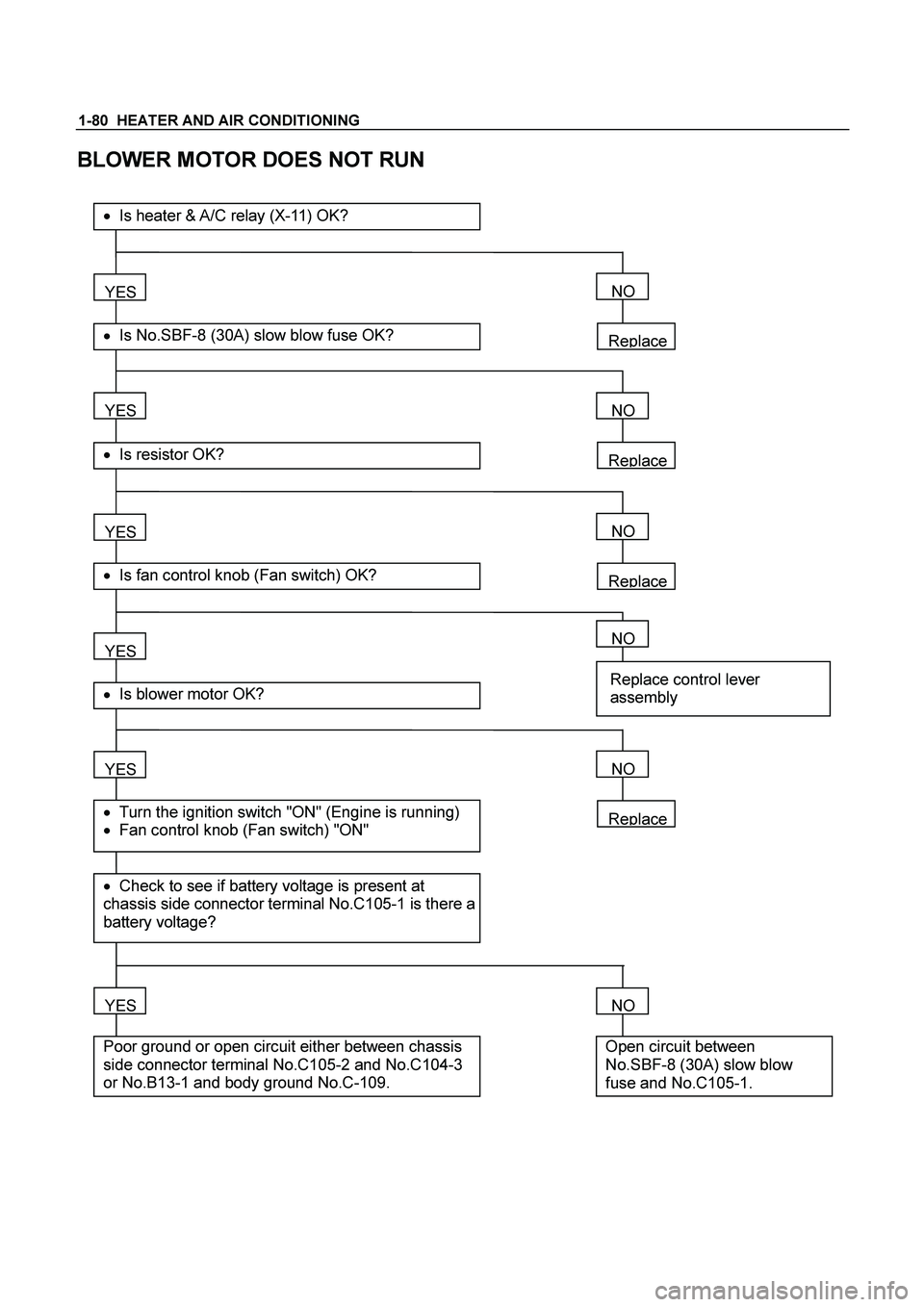
1-80 HEATER AND AIR CONDITIONING
BLOWER MOTOR DOES NOT RUN
Replace
YES
� Is No.SBF-8 (30A) slow blow fuse OK?
��Is heater & A/C relay (X-11) OK?
YES
� Is resistor OK?
YES
� Is fan control knob (Fan switch) OK?
YES
YES
� Check to see if battery voltage is present at
chassis side connector terminal No.C105-1 is there a
battery voltage?
� Turn the ignition switch "ON" (Engine is running)
� Fan control knob (Fan switch) "ON"
� Is blower motor OK?
YES
Poor ground or open circuit either between chassis
side connector terminal No.C105-2 and No.C104-3
or No.B13-1 and body ground No.C-109.
NO
Replace
NO
Replace
NO
NO
Replace control lever
assembly
Replace
NO
NO
Open circuit between
No.SBF-8 (30A) slow blow
fuse and No.C105-1.


Current flows to the blower motor through the Heater & A/C relay (X-11) to activate the rotation of the blower motor")