2004 ISUZU TF SERIES relay
[x] Cancel search: relayPage 1414 of 4264
6E–42 4JA1/4JH1 ENGINE DRIVEABILITY AND EMISSIONS
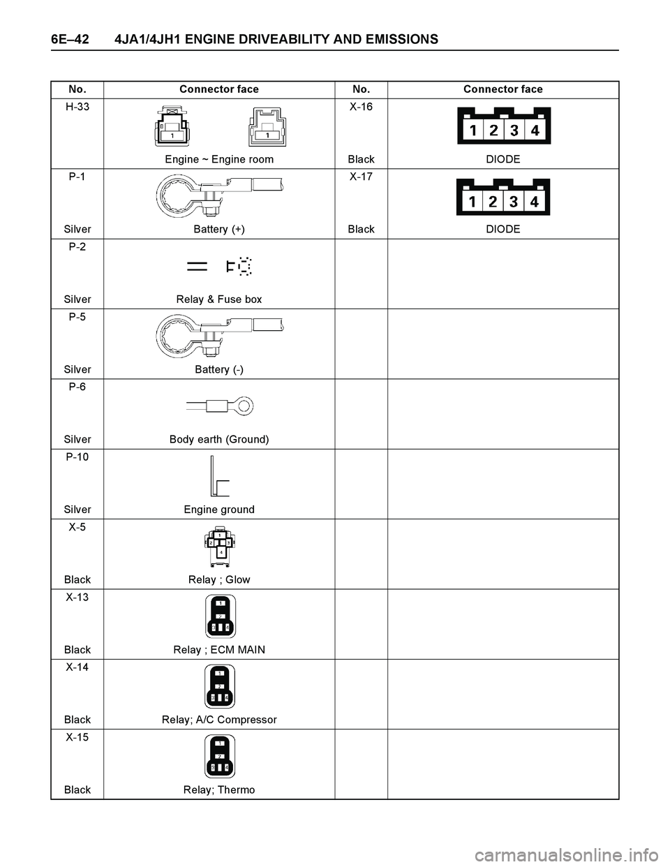
No. Connector face No. Connector face
H-33
Engine ~ Engine roomX-16
Black DIODE
P-1
Silver Battery (+)X-17
Black DIODE
P-2
Silver Relay & Fuse box
P-5
Silver Battery (-)
P-6
Silver Body earth (Ground)
P-10
Silver Engine ground
X-5
Black Relay ; Glow
X-13
Black Relay ; ECM MAIN
X-14
Black Relay; A/C Compressor
X-15
Black Relay; Thermo
Page 1415 of 4264
4JA1/4JH1 ENGINE DRIVEABILITY AND EMISSIONS 6E–43
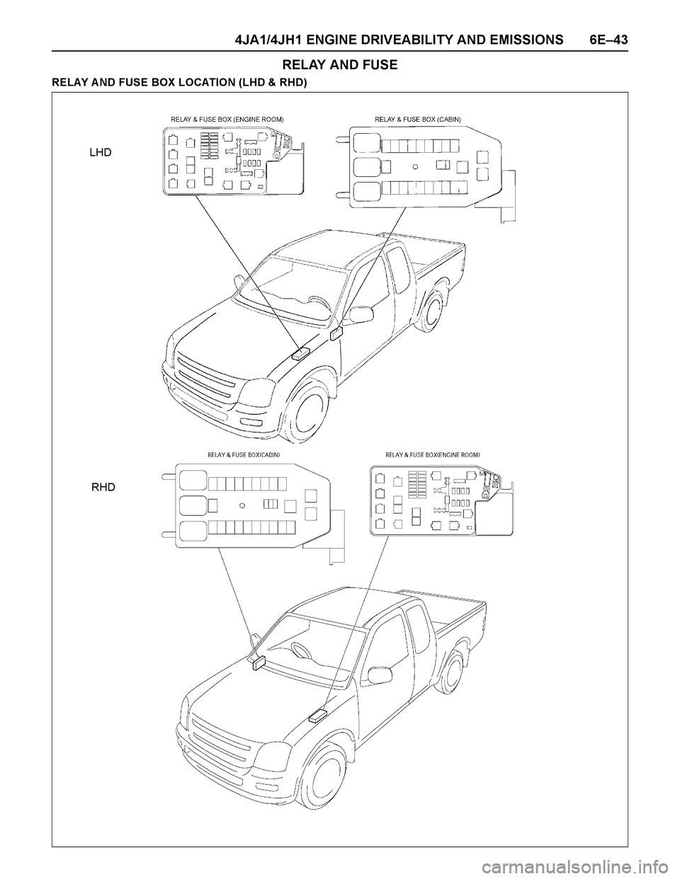
RELAY AND FUSE
RELAY A ND FUSE BOX LOCATION (LHD & RHD)
LHD
RHD
Page 1416 of 4264
6E–44 4JA1/4JH1 ENGINE DRIVEABILITY AND EMISSIONS
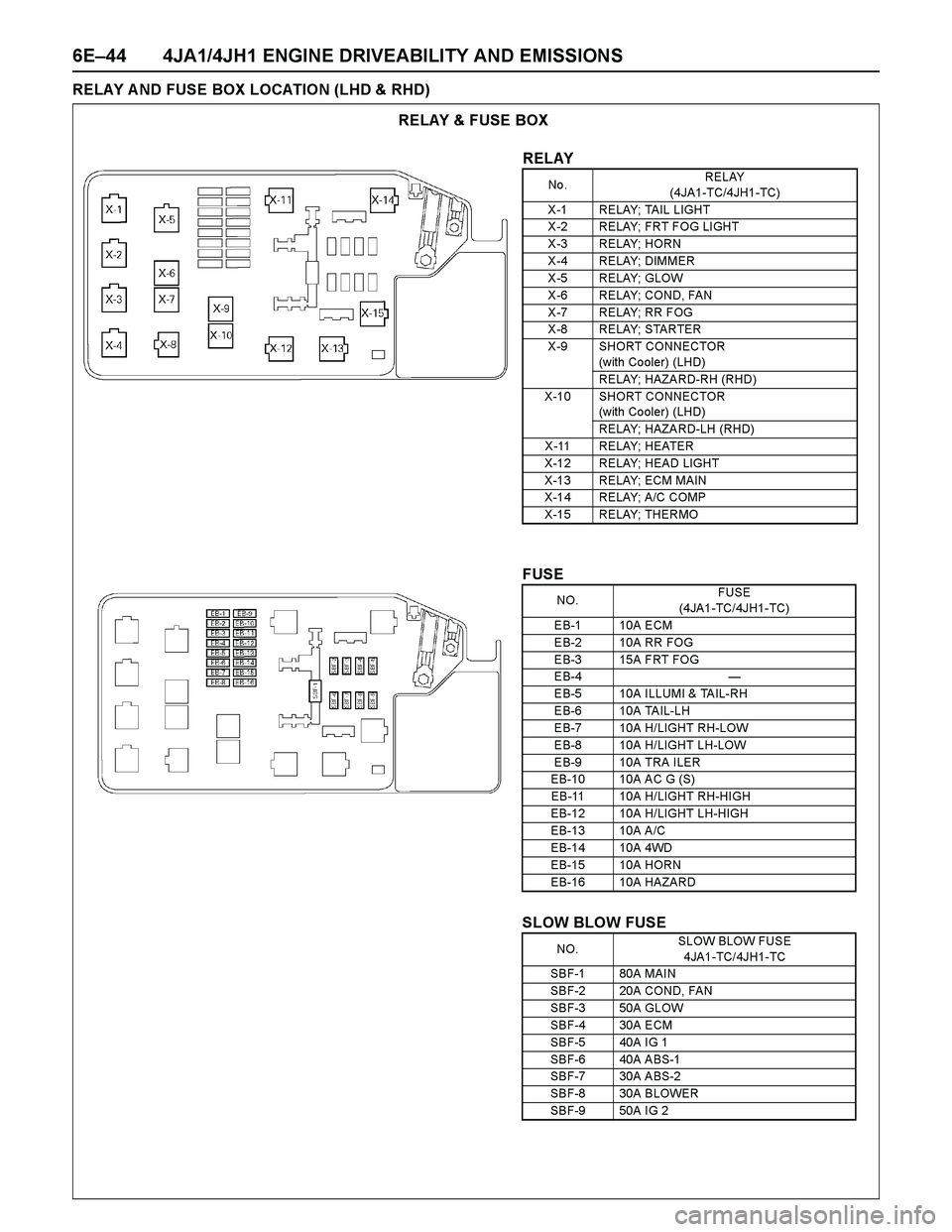
RELAY A ND FUSE BOX LOCATION (LHD & RHD)
RELAY & FUSE BOX
RELAY
No .RELAY
(4JA1-TC/4JH1-TC)
X -1 RELAY; TAIL LIGHT
X -2 RELAY; FRT F OG LI GHT
X -3 RELAY; HORN
X -4 RELAY; DIMMER
X -5 RELAY; GLOW
X -6 RELAY; COND, FAN
X -7 RELAY; RR FOG
X -8 RELAY; STARTER
X -9 SHORT CONNECTOR
(with Co oler) (LHD)
RELAY; HAZARD-RH (RHD)
X-10 SHORT CONNECTOR
(with Co oler) (LHD)
RELAY; HAZARD-LH (RHD)
X -11 RELAY; HEATER
X-12 RELAY; HEAD LIGHT
X-13 RELAY; ECM MAIN
X-14 RELAY; A/C COMP
X-15 RELAY; THERMO
FUSE
SLOW BLOW FUSE
NO.FUSE
(4JA1-TC/4JH1-TC)
EB-1 10A ECM
EB-2 10A RR FOG
EB-3 15A FRT FOG
EB-4 —
EB-5 10A ILLUMI & TAIL-RH
EB-6 10A TAIL-LH
EB-7 10A H/LIGHT RH-LOW
EB-8 10A H/LIGHT LH-LOW
EB-9 10A TRA ILER
EB-10 10A AC G (S)
EB-11 10A H/LIGHT RH-HIGH
EB-12 10A H/LIGHT LH-HIGH
EB-13 10A A/C
EB-14 10A 4WD
EB-15 10A HORN
EB-16 10A HAZARD
NO.SLOW BLOW FUSE
4JA1-TC/4JH1-TC
SBF-1 80A MAIN
SBF-2 20A COND, FAN
SBF-3 50A GLOW
SBF-4 30A ECM
SBF-5 40A IG 1
SBF-6 40A ABS-1
SBF-7 30A ABS-2
SBF-8 30A BLOWER
SBF-9 50A IG 2
Page 1417 of 4264
4JA1/4JH1 ENGINE DRIVEABILITY AND EMISSIONS 6E–45
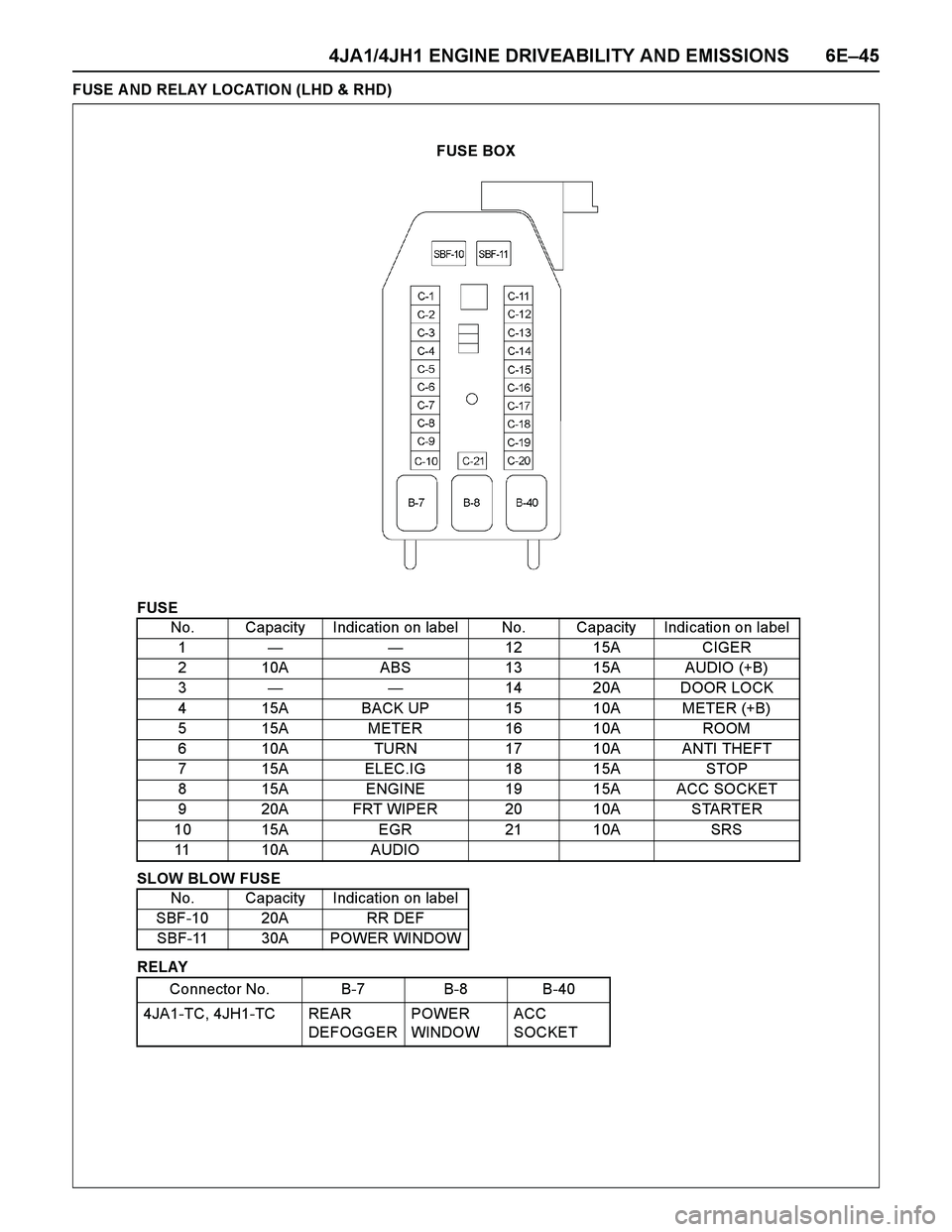
FUSE A ND RELAY LOCATION (LHD & RHD)
FUSE
SLOW BLOW FUSE
RELAYNo. Capacity Indication on label No. Capacity Indication on label
1——12 15A CIGER
2 10A ABS 13 15A AUDIO (+B)
3——14 20A DOOR LOCK
4 15A BACK UP 15 10A METER (+B)
5 15A METER 16 10A ROOM
6 10A TURN 17 10A ANTI THEFT
7 15A ELEC.IG 18 15A STOP
8 15A ENGINE 19 15A ACC SOCKET
9 20A FRT WIPER 20 10A STARTER
10 15A EGR 21 10A SRS
11 10A AUDIO
No. Capacity Indication on label
SBF-10 20A RR DEF
SBF-11 30A POWER WINDOW
Connector No. B-7 B-8 B-40
4JA1-TC, 4JH1-TC REAR
DEFOGGERPOWER
WINDOWACC
SOCKET
FUSE BOX
Page 1427 of 4264
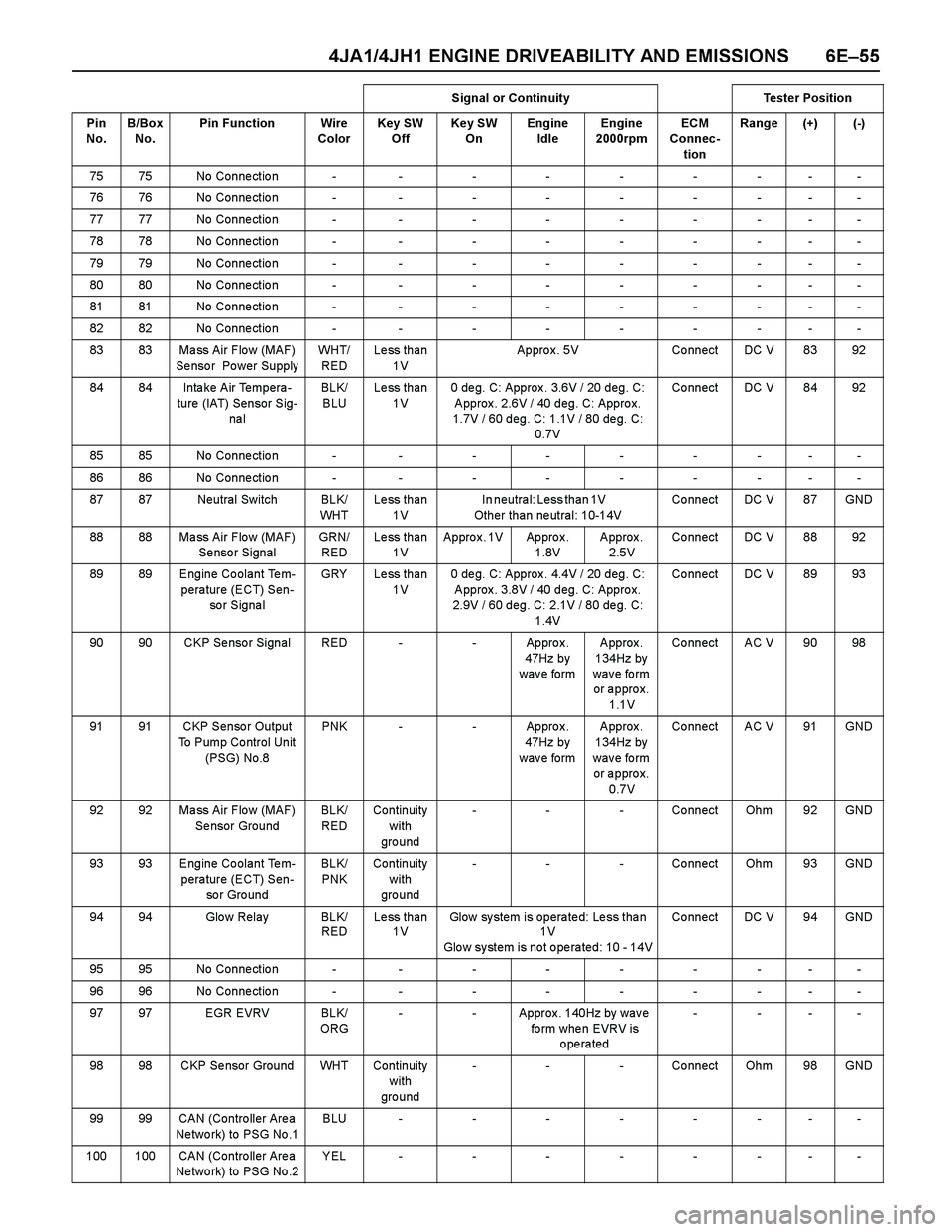
4JA1/4JH1 ENGINE DRIVEABILITY AND EMISSIONS 6E–55
75 75 No Conne ctio n - - - - - - - - -
76 76 No Conne ctio n - - - - - - - - -
77 77 No Conne ctio n - - - - - - - - -
78 78 No Conne ctio n - - - - - - - - -
79 79 No Conne ctio n - - - - - - - - -
80 80 No Conne ctio n - - - - - - - - -
81 81 No Conne ctio n - - - - - - - - -
82 82 No Conne ctio n - - - - - - - - -
83 83 Ma ss Air Flo w (MAF)
Se nso r Po wer SupplyWH T/
REDLess than
1VAppro x . 5V Co nnect DC V 83 92
84 84 Intake Air Tempera-
ture (IAT) Sensor Sig-
na lBLK/
BLULess than
1V0 deg. C: Approx. 3.6V / 20 deg. C:
Approx. 2.6V / 40 deg. C: Approx.
1.7V / 60 deg. C: 1.1V / 80 deg. C:
0.7VCo nnect DC V 84 92
85 85 No Conne ctio n - - - - - - - - -
86 86 No Conne ctio n - - - - - - - - -
87 87 Neutral Switch BLK/
WH TLess than
1VIn neutral: Less than 1V
Other than neutral: 10-14VCo nnect DC V 87 GND
88 88 Ma ss Air Flo w (MAF)
Se nso r SignalGRN/
REDLess than
1VAppro x . 1V Appro x .
1.8VApprox.
2.5VCo nnect DC V 88 92
89 89 Engine Coolant Tem-
perature (ECT) Sen-
so r S ig na lGRY Less than
1V0 deg. C: Approx. 4.4V / 20 deg. C:
Approx. 3.8V / 40 deg. C: Approx.
2.9V / 60 deg. C: 2.1V / 80 deg. C:
1.4VCo nnect DC V 89 93
90 90 CKP Se nso r Signal RED - - Appro x .
47Hz by
w a v e fo rm Approx.
134Hz by
wave form
or approx.
1.1VCo nnect AC V 90 98
91 91 CKP Senso r Output
To Pump Co ntrol Unit
(PSG) No.8PNK - - Appro x .
47Hz by
w a v e fo rm Approx.
134Hz by
wave form
or approx.
0.7VCo nnect AC V 91 GND
92 92 Ma ss Air Flo w (MAF)
Se nsor GroundBLK/
REDContinuity
with
gro und- - - Connect Ohm 92 GND
93 93 Engine Coolant Tem-
perature (ECT) Sen-
so r Gro undBLK/
PNKContinuity
with
gro und- - - Connect Ohm 93 GND
94 94 Glo w Relay BLK/
REDLess than
1VGlow system is operated: Less than
1 V
Glow system is not operated: 10 - 14VCo nnect DC V 94 GND
95 95 No Conne ctio n - - - - - - - - -
96 96 No Conne ctio n - - - - - - - - -
97 97 EGR EVRV BLK/
ORG- - Approx. 140Hz by wave
fo rm whe n EVRV is
operated----
98 98 CKP Se nsor Ground WHT Continuity
with
gro und- - - Connect Ohm 98 GND
99 99 CAN (Contro ller Are a
Ne two rk) to PSG No .1BLU--------
100 100 CAN (Contro ller Are a
Ne two rk) to PSG No .2YEL--------Signal or Continuity Tester Position
Pin
No. B/Box
No.Pin Function Wire
ColorKey SW
OffKey SW
OnEngine
IdleEngine
2000rpmECM
Connec-
tionRange (+) (-)
Page 1431 of 4264
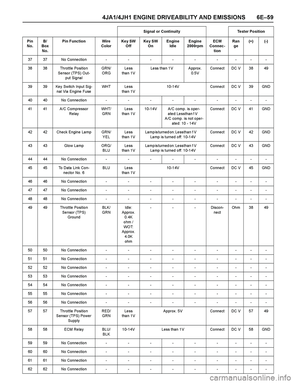
4JA1/4JH1 ENGINE DRIVEABILITY AND EMISSIONS 6E–59
3737No Connection---------
38 38 Throttle Po sitio n
Se nso r (TPS) Out-
put Signa lGRN/
ORGLe ss
tha n 1VLess than 1V Approx.
0.5VCo nnect DC V 38 49
39 39 Ke y Switch Input Sig-
nal Via Engine FuseWH T L e s s
tha n 1V10-14V Co nnect DC V 39 GND
4040No Connection---------
41 41 A/C Compressor
RelayWH T/
GRNLe ss
tha n 1V10-14V A/C comp. is o pe r-
ated: Less than 1V
A/C comp. is no t o pe r-
ate d: 10 - 14VCo nnect DC V 41 GND
42 42 Check Engine La mp GRN/
YELLe ss
tha n 1VLamp is turned on: Less than 1V
Lamp is turned off: 10-14VCo nnect DC V 42 GND
43 43 Glo w Lamp ORG/
BLULe ss
tha n 1VLamp is turned on: Less than 1V
Lamp is turned off: 10-14VCo nnect DC V 43 GND
4444No Connection---------
45 45 To Data Link Co n-
necto r No . 6BLU Less
tha n 1V10-14V Co nnect DC V 45 GND
4646No Connection---------
4747No Connection---------
4848No Connection---------
49 49 Throttle Po sitio n
Se nso r (TPS)
GroundBLK/
GRNIdle:
Appro x.
0.4K
ohm /
WO T:
Appro x.
4.0K
ohm---Discon-
ne ctOh m 3 8 4 9
5050No Connection---------
5151No Connection---------
5252No Connection---------
5353No Connection---------
5454No Connection---------
5555No Connection---------
5656No Connection---------
57 57 Throttle Po sitio n
Senso r (TPS) Po wer
SupplyRED/
GRNLe ss
tha n 1VApprox. 5V Connect DC V 57 49
58 58 ECM Re la y BLU/
BLK10-14V Less than 1V Connect DC V 58 GND
5959No Connection---------
6060No Connection---------
6161No Connection---------
6262No Connection---------Signal or Continuity Tester Position
Pin
No. B/
Box
No.Pin Function Wire
ColorKey SW
OffKey SW
OnEngine
IdleEngine
2000rpmECM
Connec-
tionRan
ge(+) (-)
Page 1451 of 4264
4JA1/4JH1 ENGINE DRIVEABILITY AND EMISSIONS 6E–79
–Are there areas subjected to vibration or
movement (engine, transmission or
suspension)?
–Are there areas ex posed to moisture, road salt
or other corrosives (battery acid, oil or other
fluids)?
–Are there common mounting areas with other
systems/components?
–Have previous repairs been performed to wiring,
connectors, components or mounting areas
(causing pinched wires between panels and
drivetrain or suspension components without
causing and immediate problem)?
–Does the vehicle have aftermarket or dealer-
installed equipment (radios, telephone, etc.)
Step 2: Isolate the problem
At this point, you should have a good idea of what could
cause the present condition, as well as could not cause
the condition. Actions to take include the following:
Divide (and separate, where possible) the system or
circuit into smaller sections
Confine the problem to a smaller area of the vehicle
(start with main harness connections while removing
panels and trim as necessary in order to eliminate
large vehicle sections from further investigation)
For two or more circuits that do not share a common
power or ground, concentrate on areas where
harnesses are routed together or connectors are
shared (refer to the following hints)
Hints
Though the symptoms may vary, basic electrical failures
are generally caused by:
Loose connections:
–Open/high resistance in terminals, splices,
connectors or grounds
Incorrect connector/harness routing (usually in new
vehicles or after a repair has been made):
–Open/high resistance in terminals, splices,
connectors of grounds
Corrosion and wire damage:
–Open/high resistance in terminals, splices,
connectors of grounds
Component failure:
–Opens/short and high resistance in relays,
modules, switches or loads
Aftermarket equipment affecting normal operation of
other systems
You may isolate circuits by:
Unplugging connectors or removing a fuse to
separate one part of the circuit from another part
Operating shared circuits and eliminating those that
function normally from the suspect circuit
If only one component fails to operate, begin testingat the component
If a number of components do no operate, begin tests
at the area of commonality (such as power sources,
ground circuits, switches or major connectors)
What resources you should use
Whenever appropriate, you should use the following
resources to assist in the diagnostic process:
Service manual
Technical equipment (for data analysis)
Ex perience
Technical Assistance
Circuit testing tools
5d. Intermittent Diagnosis
By definition, an intermittent problem is one that does
not occur continuously and will occur when certain
conditions are met. All these conditions, however, may
not be obvious or currently known. Generally,
intermittents are caused by:
Faulty electrical connections and wiring
Malfunctioning components (such as sticking relays,
solenoids, etc.)
EMI/RFI (Electromagnetic/radio frequency
interference)
Aftermarket equipment
Intermittent diagnosis requires careful analysis of
suspected systems to help prevent replacing good
parts. This may involve using creativity and ingenuity to
interpret customer complaints and simulating all
ex ternal and internal system conditions to duplicate the
problem.
What you should do
Step 1: A cquire information
A thorough and comprehensive customer check sheet
is critical to intermittent problem diagnosis. You should
require this, since it will dictate the diagnostic starting
point. The vehicle service history file is another
source for accumulating information about the
complaint.
Step 2: A nalyze the intermittent problem
Analyze the customer check sheet and service history
file to determine conditions relevant to the suspect
system(s).
Using service manual information, you must identify,
trace and locate all electrical circuits related to the
malfunctioning system(s). If there is more than one
system failure, you should identify, trace and locate
areas of commonality shared by the suspect circuits.
Page 1459 of 4264
4JA1/4JH1 ENGINE DRIVEABILITY AND EMISSIONS 6E–87
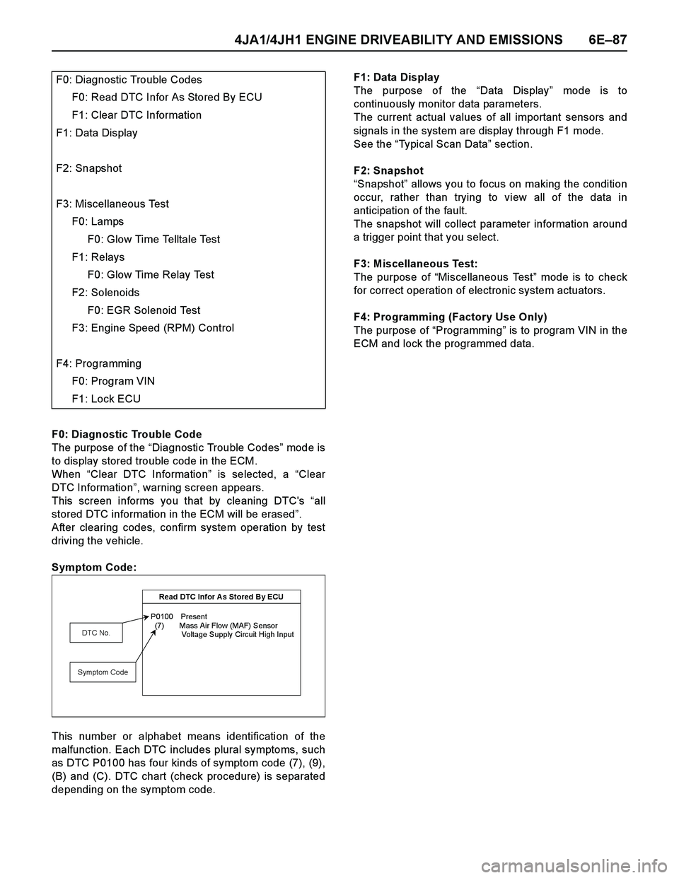
F0: Diagnostic Trouble Code
The purpose of the “Diagnostic Trouble Codes” mod e i s
to display stored trouble code in the ECM.
When “Clear DTC Information” is selected, a “Clear
DTC Information”, warning screen appears.
This screen informs you that by cleaning DTC's “all
stored DTC information in the ECM will be erased”.
After clearing codes, confirm system operation by test
driving the vehicle.
Symptom Code:
This number or alphabet means identification of the
malfunction. Each DTC includes plural symptoms, such
as DTC P0100 has four kinds of symptom code (7), (9),
(B) and (C). DTC chart (check procedure) is separated
depending on the symptom code.F1: Data Display
The purpose of the “Data Display” mode is to
continuously monitor data parameters.
The current actual values of all important sensors and
signals in the system are display through F1 mode.
See the “Typical Scan Data” section.
F2: Snapshot
“Snapshot” allows you to focus on making the condition
occur, rather than trying to view all of the data in
anticipation of the fault.
The snapshot will collect parameter information around
a trigger point that you select.
F3: Miscellaneous Test:
The purpose of “Miscellaneous Test” mode is to check
for correct operation of electronic system actuators.
F4: Programming (Factory Use Only)
The purpose of “Programming” is to program VIN in the
ECM and lock the programmed data. F0: Diagnostic Trouble Codes
F0: Read DTC Infor As Stored By ECU
F1: Clear DTC Information
F1: Data Display
F2: Snapshot
F3: Miscellaneous Test
F0: Lamps
F0: Glow Time Telltale Test
F1: Relays
F0: Glow Time Relay Test
F2: Solenoids
F0: EGR Solenoid Test
F3: Engine Speed (RPM) Control
F4: Programming
F0: Program VIN
F1: Lock ECU
Read DTC Infor A s Stored By ECU
P0100 Present
(7) Mass Air Flow (MAF) Sensor
Voltage Supply Circuit High Input
DTC No.
Symptom Code