2004 ISUZU TF SERIES relay
[x] Cancel search: relayPage 1780 of 4264
6E–408 4JA1/4JH1 ENGINE DRIVEABILITY AND EMISSIONS
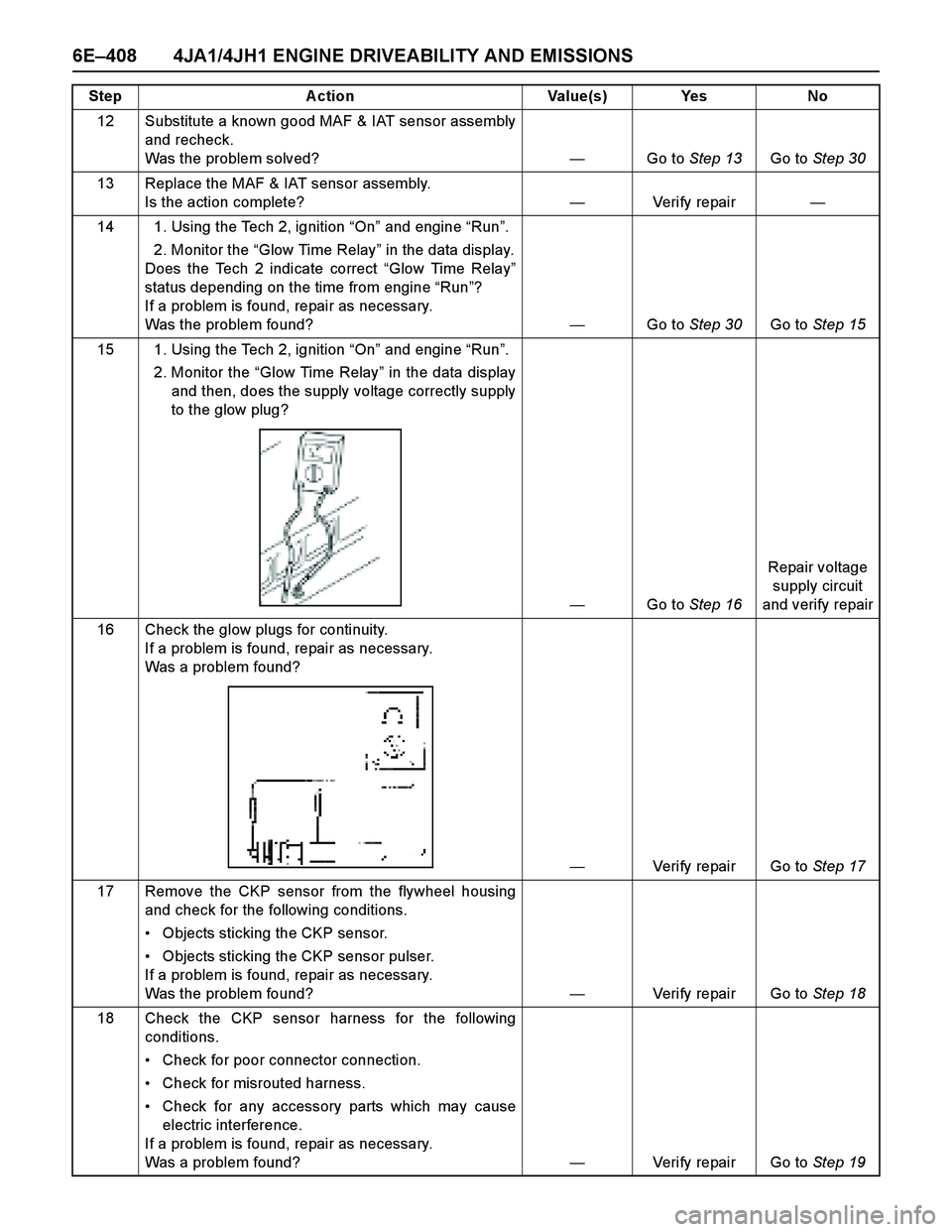
12 Substitute a known good MAF & IAT sensor assembly
and recheck.
Was the problem solved?—Go to Step 13Go to Step 30
13 Replace the MAF & IAT sensor assembly.
Is the action complete?—Veri fy repai r—
14 1. Using the Tech 2, ignition “On” and engine “Run”.
2. Monitor the “Glow Time Relay” in the data display.
Does the Tech 2 indicate correct “Glow Time Relay”
status depending on the time from engine “Run”?
If a problem is found, repair as necessary.
Was the problem found?—Go to Step 30Go to Step 15
15 1. Using the Tech 2, ignition “On” and engine “Run”.
2. Monitor the “Glow Time Relay” in the data display
and then, does the supply voltage correctly supply
to the glow plug?
—Go to Step 16Repair voltage
supply circuit
and verify repair
16 Check the glow plugs for continuity.
If a problem is found, repair as necessary.
Was a problem found?
—Verify repair Go to Step 17
17 Remove the CKP sensor from the flywheel housing
and check for the following conditions.
Objects sticking the CKP sensor.
Objects sticking the CKP sensor pulser.
If a problem is found, repair as necessary.
Was the problem found? —Verify repair Go to Step 18
18 Check the CKP sensor harness for the following
conditions.
Check for poor connector connection.
Check for misrouted harness.
Check for any accessory parts which may cause
electric interference.
If a problem is found, repair as necessary.
Was a problem found? —Verify repair Go to Step 19 Step Action Value(s) Yes No
Page 1829 of 4264
ENGINE MECHANICAL (6VE1 3.5L) 6A-5
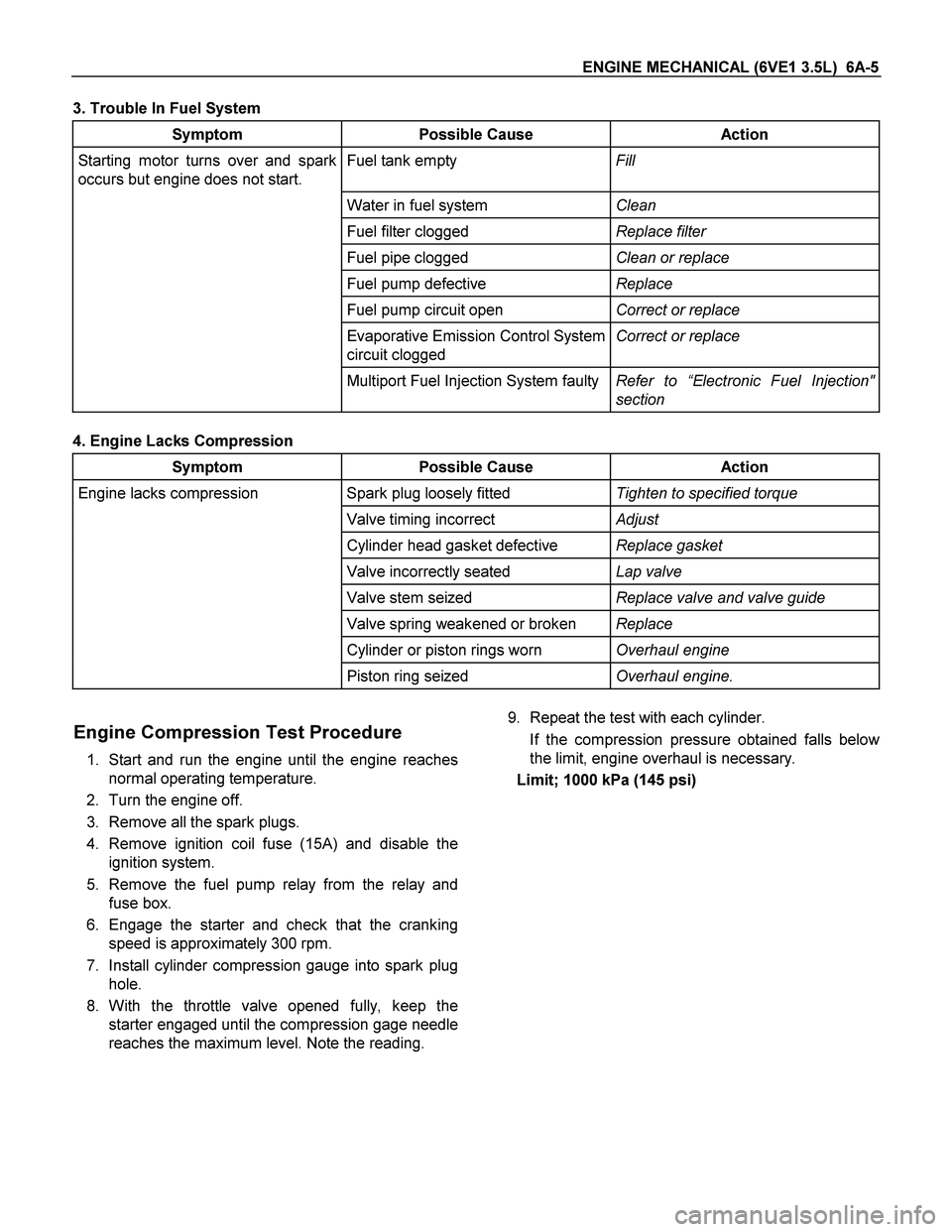
3. Trouble In Fuel System
Symptom Possible Cause Action
Starting motor turns over and spark
occurs but engine does not start. Fuel tank empty Fill
Water in fuel system Clean
Fuel filter clogged Replace filter
Fuel pipe clogged Clean or replace
Fuel pump defective Replace
Fuel pump circuit open Correct or replace
Evaporative Emission Control System
circuit clogged Correct or replace
Multiport Fuel Injection System faultyRefer to “Electronic Fuel Injection"
section
4. Engine Lacks Compression
Symptom Possible Cause Action
Engine lacks compression Spark plug loosely fitted Tighten to specified torque
Valve timing incorrect Adjust
Cylinder head gasket defective Replace gasket
Valve incorrectly seated Lap valve
Valve stem seized Replace valve and valve guide
Valve spring weakened or broken Replace
Cylinder or piston rings worn Overhaul engine
Piston ring seized Overhaul engine.
Engine Compression Test Procedure
1. Start and run the engine until the engine reaches
normal operating temperature.
2. Turn the engine off.
3. Remove all the spark plugs.
4. Remove ignition coil fuse (15A) and disable the
ignition system.
5. Remove the fuel pump relay from the relay and
fuse box.
6. Engage the starter and check that the cranking
speed is approximately 300 rpm.
7. Install cylinder compression gauge into spark plug
hole.
8. With the throttle valve opened fully, keep the
starter engaged until the compression gage needle
reaches the maximum level. Note the reading.
9. Repeat the test with each cylinder.
If the compression pressure obtained falls belo
w
the limit, engine overhaul is necessary.
Limit; 1000 kPa (145 psi)
Page 1830 of 4264
6A-6 ENGINE MECHANICAL (6VE1 3.5L)
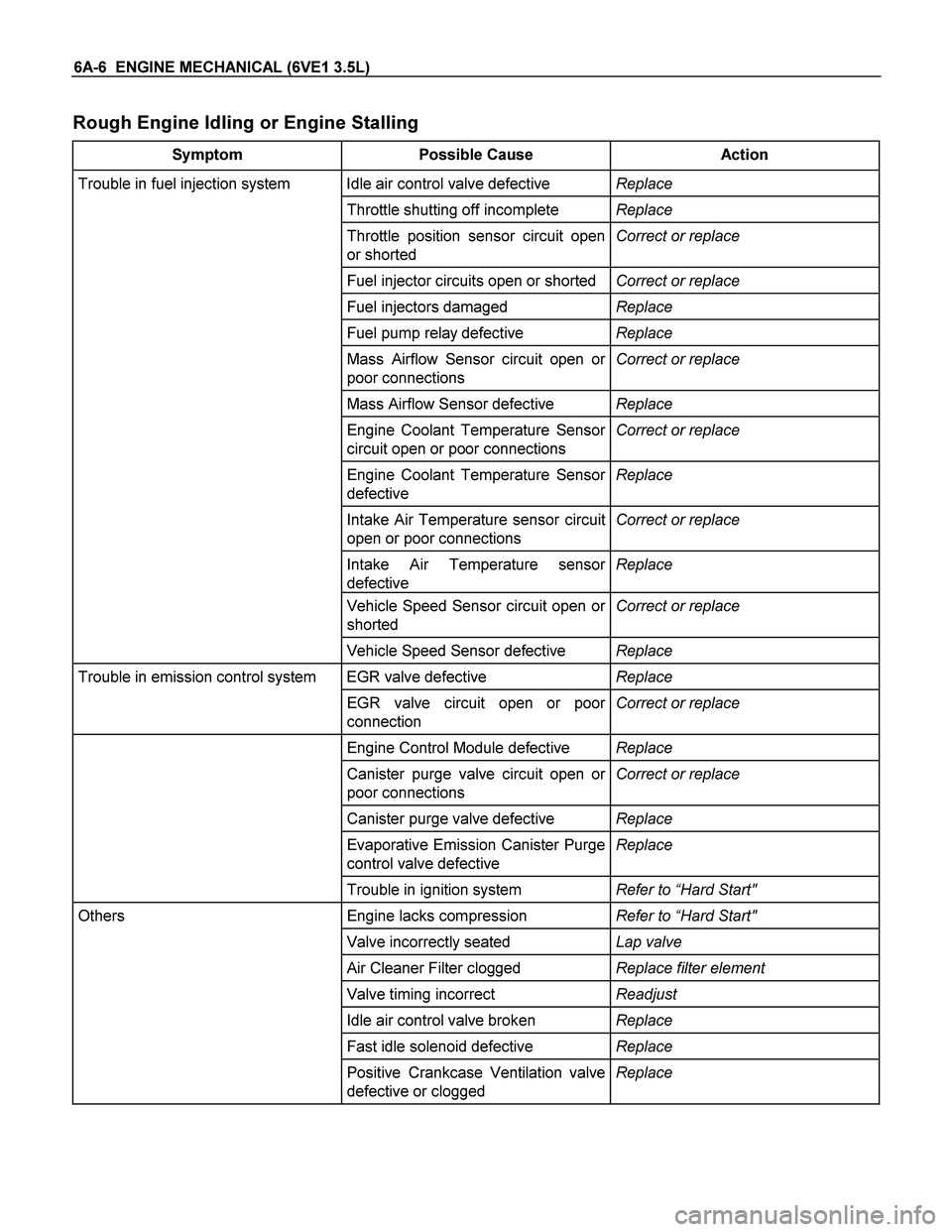
Rough Engine Idling or Engine Stalling
Symptom Possible Cause Action
Trouble in fuel injection system Idle air control valve defective Replace
Throttle shutting off incomplete Replace
Throttle position sensor circuit open
or shorted Correct or replace
Fuel injector circuits open or shortedCorrect or replace
Fuel injectors damaged Replace
Fuel pump relay defective Replace
Mass Airflow Sensor circuit open or
poor connections Correct or replace
Mass Airflow Sensor defective Replace
Engine Coolant Temperature Sensor
circuit open or poor connections Correct or replace
Engine Coolant Temperature Sensor
defective Replace
Intake Air Temperature sensor circuit
open or poor connections Correct or replace
Intake Air Temperature sensor
defective Replace
Vehicle Speed Sensor circuit open or
shorted Correct or replace
Vehicle Speed Sensor defective Replace
Trouble in emission control system EGR valve defective Replace
EGR valve circuit open or poor
connection Correct or replace
Engine Control Module defective Replace
Canister purge valve circuit open or
poor connections Correct or replace
Canister purge valve defective Replace
Evaporative Emission Canister Purge
control valve defective Replace
Trouble in ignition system Refer to “Hard Start"
Others Engine lacks compression Refer to “Hard Start"
Valve incorrectly seated Lap valve
Air Cleaner Filter clogged Replace filter element
Valve timing incorrect Readjust
Idle air control valve broken Replace
Fast idle solenoid defective Replace
Positive Crankcase Ventilation valve
defective or clogged Replace
Page 1839 of 4264

ENGINE MECHANICAL (6VE1 3.5L) 6A-15
Abnormal Combustion
Symptom Possible Cause Action
Trouble in fuel system Fuel pressure control valve defectiveReplace
Fuel filter clogged Replace
Fuel pump clogged Clean or replace
Fuel tank or fuel pipe clogged Clean or replace
Fuel injector clogged Clean or replace
Fuel pump relay defective Replace
Power supply cable for fuel pump
broken or poor connections Reconnect, correct or replace
Mass Airflow (MAF) Sensor circuit
open or defective Correct or replace
MAF Sensor defective Replace
Engine Coolant Temperature (ECT)
Sensor circuit open or shorted Correct or replace
ECT Sensor defective Replace
Throttle Position Sensor adjustment
incorrect Readjust
Throttle Position Sensor defective Replace
Throttle Position Sensor connector
poor connections Reconnect
Vehicle Speed Sensor cable poor
connections or defective Correct or replace
Vehicle Speed Sensor loosely fixed Fix tightly
Vehicle Speed Sensor in wrong
contact or defective Replace
Engine Control Module cable poor
connections or defective Correct or replace
Page 1943 of 4264
ENGINE FUEL (6VE1 3.5L) 6C-1
ENGINE
ENGINE FUEL (6VE1 3.5L)
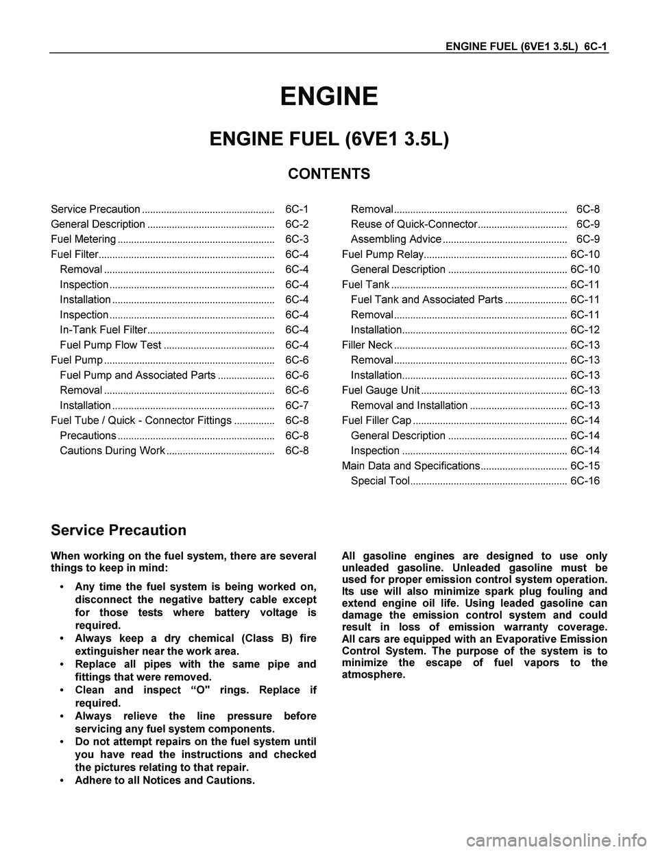
CONTENTS
Service Precaution................................................. 6C-1
General Description............................................... 6C-2
Fuel Metering.......................................................... 6C-3
Fuel Filter................................................................. 6C-4
Removal............................................................... 6C-4
Inspection............................................................. 6C-4
Installation............................................................ 6C-4
Inspection............................................................. 6C-4
In-Tank Fuel Filter............................................... 6C-4
Fuel Pump Flow Test......................................... 6C-4
Fuel Pump............................................................... 6C-6
Fuel Pump and Associated Parts..................... 6C-6
Removal............................................................... 6C-6
Installation............................................................ 6C-7
Fuel Tube / Quick - Connector Fittings............... 6C-8
Precautions.......................................................... 6C-8
Cautions During Work........................................ 6C-8
Removal................................................................ 6C-8
Reuse of Quick-Connector................................. 6C-9
Assembling Advice.............................................. 6C-9
Fuel Pump Relay..................................................... 6C-10
General Description............................................ 6C-10
Fuel Tank................................................................. 6C-11
Fuel Tank and Associated Parts....................... 6C-11
Removal................................................................ 6C-11
Installation............................................................. 6C-12
Filler Neck................................................................ 6C-13
Removal................................................................ 6C-13
Installation............................................................. 6C-13
Fuel Gauge Unit...................................................... 6C-13
Removal and Installation.................................... 6C-13
Fuel Filler Cap......................................................... 6C-14
General Description............................................ 6C-14
Inspection............................................................. 6C-14
Main Data and Specifications................................ 6C-15
Special Tool.......................................................... 6C-16
Service Precaution
When working on the fuel system, there are several
things to keep in mind:
Any time the fuel system is being worked on,
disconnect the negative battery cable except
for those tests where battery voltage is
required.
Always keep a dry chemical (Class B) fire
extinguisher near the work area.
Replace all pipes with the same pipe and
fittings that were removed.
Clean and inspect “O" rings. Replace i
f
required.
Always relieve the line pressure before
servicing any fuel system components.
Do not attempt repairs on the fuel system until
you have read the instructions and checked
the pictures relating to that repair.
Adhere to all Notices and Cautions.
All gasoline engines are designed to use only
unleaded gasoline. Unleaded gasoline must be
used for proper emission control system operation.
Its use will also minimize spark plug fouling and
extend engine oil life. Using leaded gasoline can
damage the emission control system and could
result in loss of emission warranty coverage.
All cars are equipped with an Evaporative Emission
Control System. The purpose of the system is to
minimize the escape of fuel vapors to the
atmosphere.
Page 1947 of 4264
ENGINE FUEL (6VE1 3.5L) 6C-5
Fuel Pump Flow Test
If reduction of fuel supply is suspected, perform the
following checks.
1. Make sure that there is fuel in the tank.
2. With the engine running, check the fuel feed pipe
and hose from fuel tank to injector for evidence o
f
leakage. Retighten, if pipe or hose connection is
loose. Also, check pipes and hoses for squashing
or clogging.
3. Insert the hose from fuel feed pipe into a clean
container, and check for fuel pump flow rate.
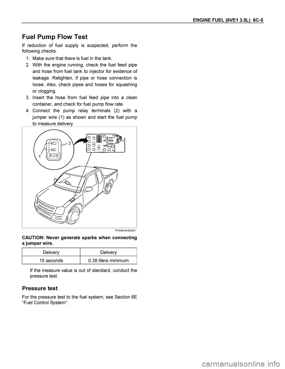
4. Connect the pump relay terminals (2) with a
jumper wire (1) as shown and start the fuel pump
to measure delivery.
RTW36CSH000201
CAUTION: Never generate sparks when connecting
a jumper wire.
Delivery Delivery
15 seconds 0.38 liters minimum
If the measure value is out of standard, conduct the
pressure test.
Pressure test
For the pressure test to the fuel system, see Section 6E
“Fuel Control System".
Page 1952 of 4264
6C-10 ENGINE FUEL (6VE1 3.5L)
Fuel Pump Relay
General Description
In order to control the fuel pump and sender assembly
(FPAS) operation, the FPAS relay is provided. When
the starter switch is turned to “ON" position, the FPAS
relay operates the FPAS for 2 seconds.
When it is turned to “START" position, the Engine
Control Module receives the reference pulse from the
Ignition Control Module and it operates the relay, again
causing the FPAS to feed fuel.
Page 1974 of 4264
6D3-2 STARTING AND CHARGING SYSTEM (6VE1 3.5L)
Starting System
General Description
Cranking Circuit
The cranking system consists of a battery, starter,
starter switch, starter relay, etc. These main
components are connected.
Starter
The cranking system employs a magnetic type
reduction starter in which the motor shaft is also used
as a pinion shaft. When the starter switch is turned on,
the contacts of magnetic switch are closed, and the
armature rotates. At the same time, the plunger is
attracted, and the pinion is pushed forward by the shif
t
lever to mesh with the ring gear.
Then, the ring gear runs to start the engine. When the
engine starts and the starter switch is turned off, the
plunger returns, the pinion is disengaged from the ring
gear, and the armature stops rotation. When the engine
speed is higher than the pinion, the pinion idles, so tha
t
the armature is not driven.