Page 2119 of 4264
3.5L ENGINE DRIVEABILITY AND EMISSIONS 6E-123
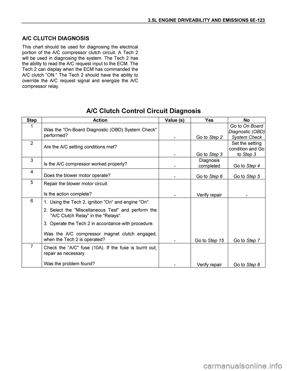
A/C CLUTCH DIAGNOSIS
This chart should be used for diagnosing the electrical
portion of the A/C compressor clutch circuit. A Tech 2
will be used in diagnosing the system. The Tech 2 has
the ability to read the A/C request input to the ECM. The
Tech 2 can display when the ECM has commanded the
A/C clutch “ON." The Tech 2 should have the ability to
override the A/C request signal and energize the A/C
compressor relay.
A/C Clutch Control Circuit Diagnosis
Step Action Value (s) Yes No
1
Was the "On-Board Diagnostic (OBD) System Check"
performed?
- Go to Step 2 Go to On Board
Diagnostic (OBD)
System Check
2
Are the A/C setting conditions met?
- Go to Step 3 Set the setting
condition and Go
to Step 3
3
Is the A/C compressor worked properly?
- Diagnosis
completed Go to Step 4
4
Does the blower motor operate?
- Go to Step 6 Go to Step 5
5
Repair the blower motor circuit.
Is the action complete?
- Verify repair -
6
1. Using the Tech 2, ignition "On" and engine "On".
2. Select the "Miscellaneous Test" and perform the
"A/C Clutch Relay" in the "Relays".
3. Operate the Tech 2 in accordance with procedure.
Was the A/C compressor magnet clutch engaged,
when the Tech 2 is operated?
- Go to Step 15 Go to Step 7
7
Check the "A/C" fuse (10A). If the fuse is burnt out,
repair as necessary.
Was the problem found?
- Verify repair Go to Step 8
Page 2120 of 4264
6E-124 3.5L ENGINE DRIVEABILITY AND EMISSIONS
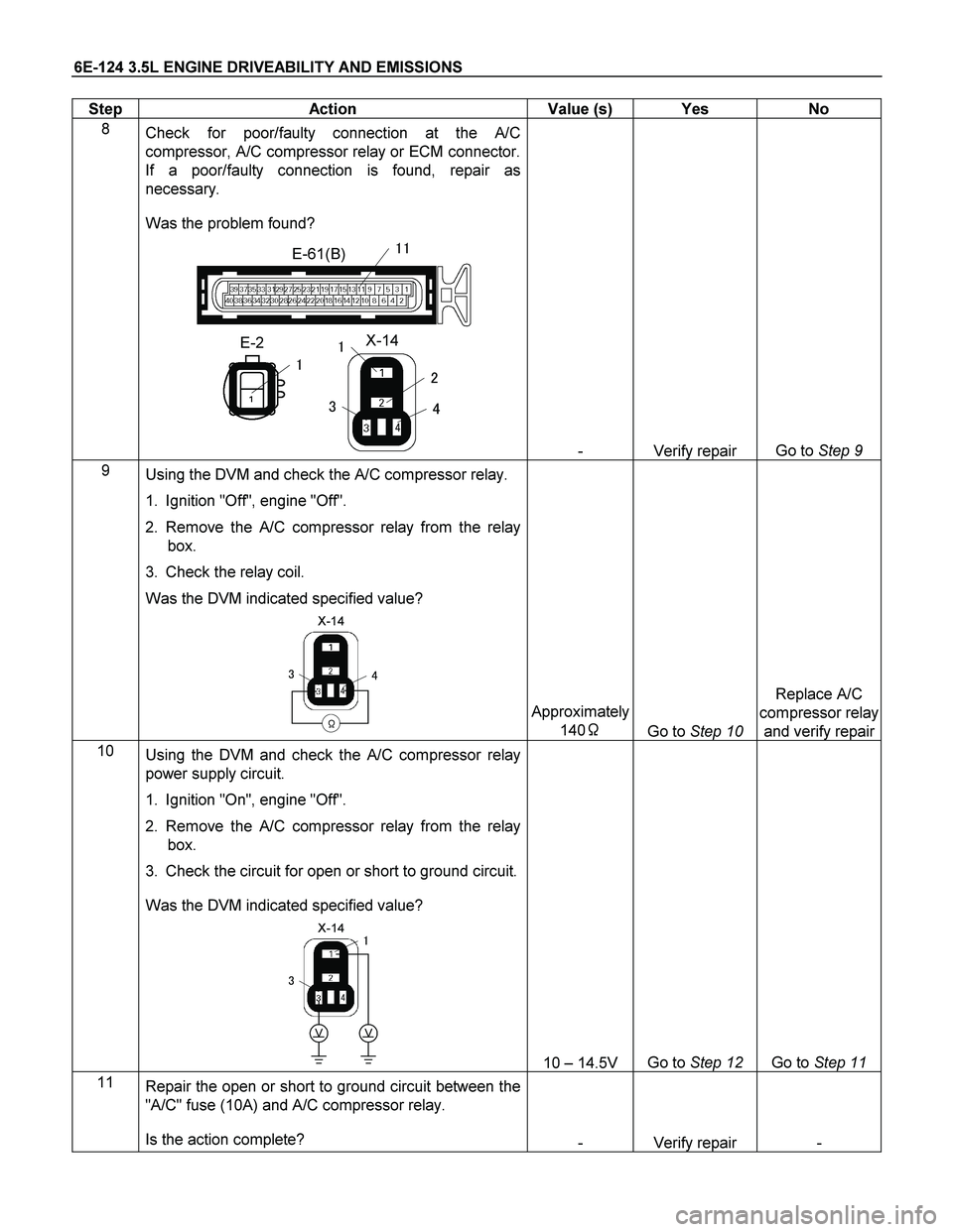
Step Action Value (s) Yes No
8
Check for poor/faulty connection at the A/C
compressor, A/C compressor relay or ECM connector.
If a poor/faulty connection is found, repair as
necessary.
Was the problem found?
E-2
�
X-14
�
�
�
�
�
E-61(B)��
- Verify repair Go to Step 9
9
� Using the DVM and check the A/C compressor relay.
1. Ignition "Off", engine "Off".
2. Remove the A/C compressor relay from the relay
box.
3. Check the relay coil.
Was the DVM indicated specified value?
X-14
���
�
Approximately
140�
Go to Step 10 Replace A/C
compressor relay
and verify repair
10
Using the DVM and check the A/C compressor relay
power supply circuit.
1. Ignition "On", engine "Off".
2. Remove the A/C compressor relay from the relay
box.
3. Check the circuit for open or short to ground circuit.
Was the DVM indicated specified value?
X-14
�
�
�
VV
10 – 14.5V Go to Step 12 Go to Step 11
11
Repair the open or short to ground circuit between the
"A/C" fuse (10A) and A/C compressor relay.
Is the action complete?
- Verify repair -
Page 2121 of 4264
3.5L ENGINE DRIVEABILITY AND EMISSIONS 6E-125
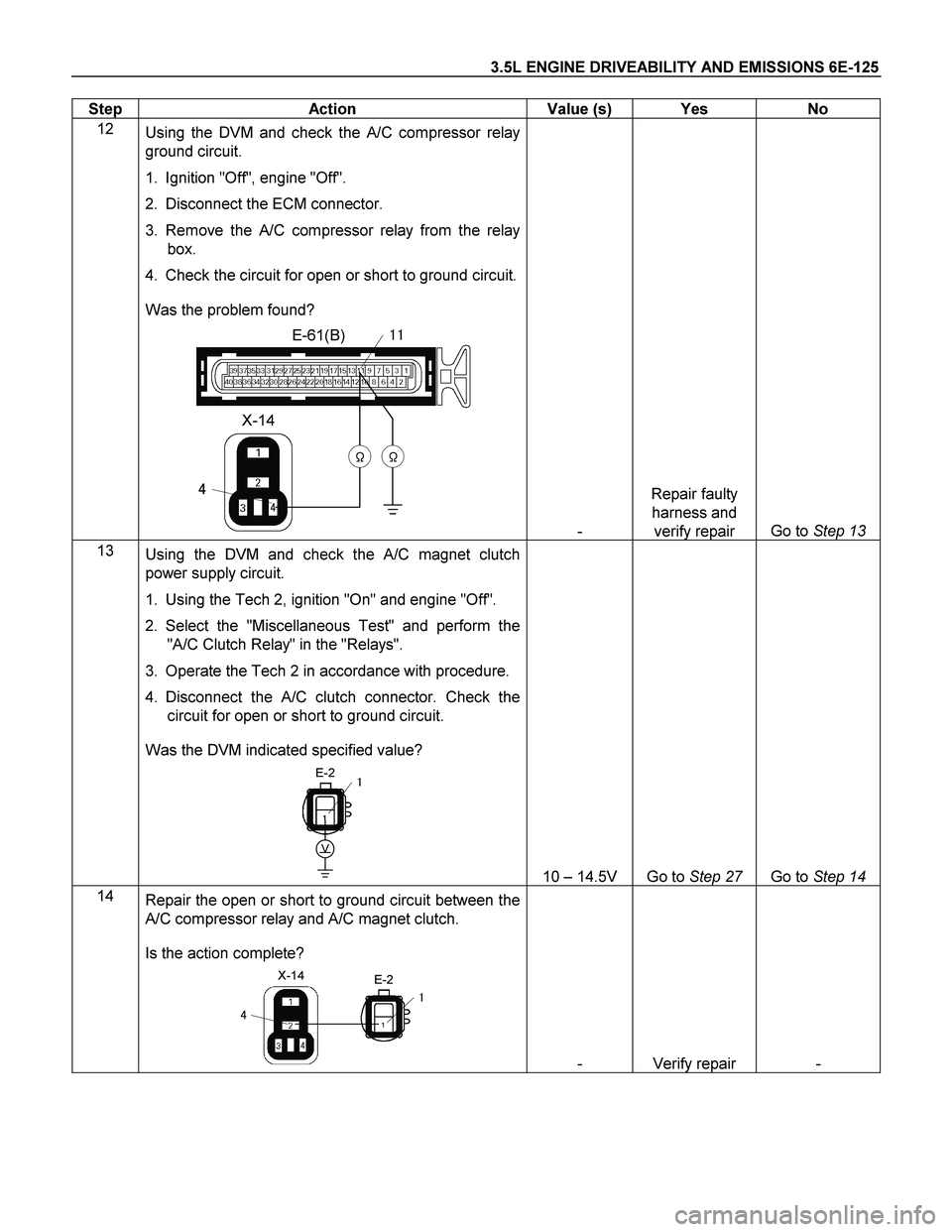
Step Action Value (s) Yes No
12
� Using the DVM and check the A/C compressor relay
ground circuit.
1. Ignition "Off", engine "Off".
2. Disconnect the ECM connector.
3. Remove the A/C compressor relay from the relay
box.
4. Check the circuit for open or short to ground circuit.
Was the problem found?
E-61(B)
X-14
�
�
��
��
- Repair faulty
harness and
verify repair Go to Step 13
13
Using the DVM and check the A/C magnet clutch
power supply circuit.
1. Using the Tech 2, ignition "On" and engine "Off".
2. Select the "Miscellaneous Test" and perform the
"A/C Clutch Relay" in the "Relays".
3. Operate the Tech 2 in accordance with procedure.
4. Disconnect the A/C clutch connector. Check the
circuit for open or short to ground circuit.
Was the DVM indicated specified value?
E-2
V
�
10 – 14.5V Go to Step 27 Go to Step 14
14
Repair the open or short to ground circuit between the
A/C compressor relay and A/C magnet clutch.
Is the action complete?
E-2X-14
�
�
�
- Verify repair -
Page 2122 of 4264
6E-126 3.5L ENGINE DRIVEABILITY AND EMISSIONS
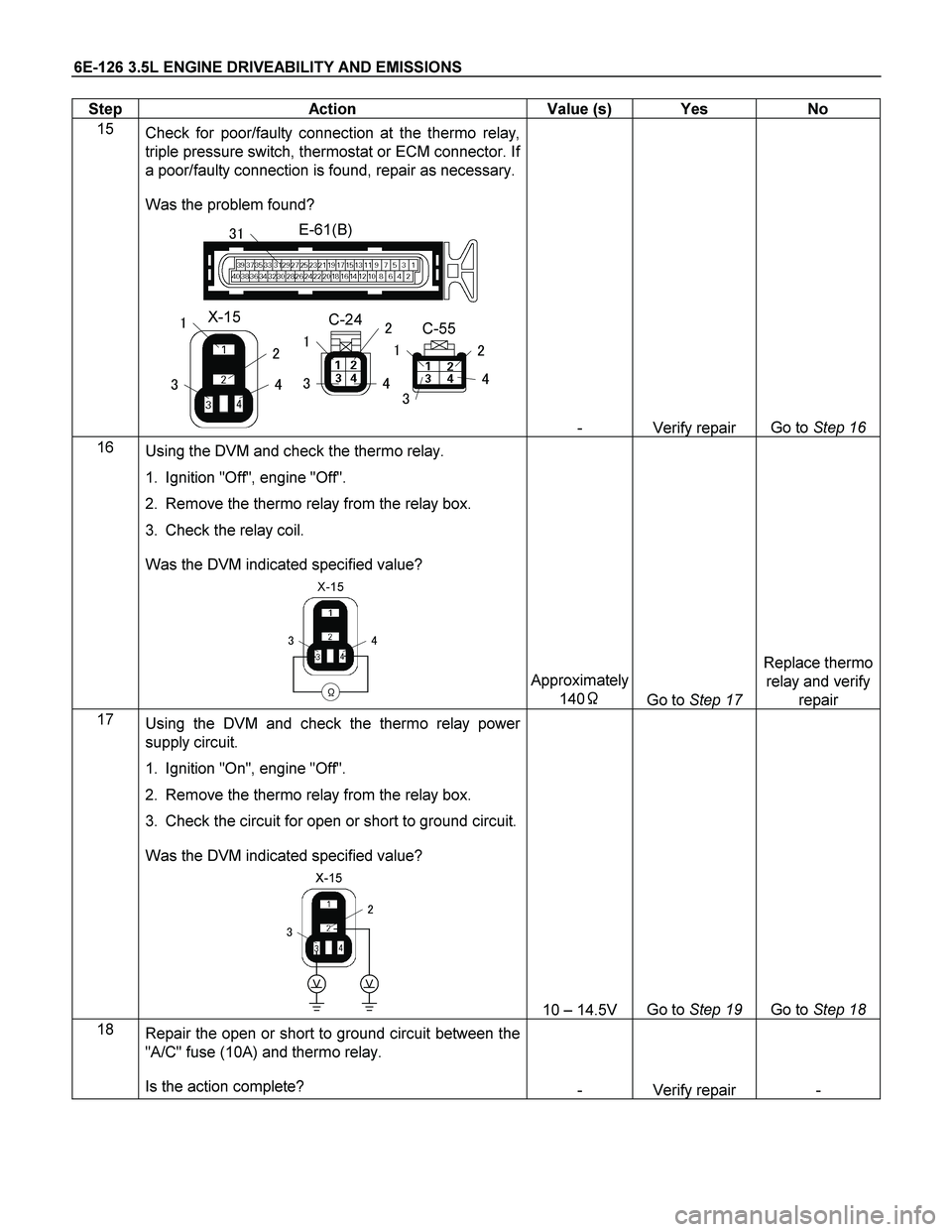
Step Action Value (s) Yes No
15
Check for poor/faulty connection at the thermo relay,
triple pressure switch, thermostat or ECM connector. If
a poor/faulty connection is found, repair as necessary.
Was the problem found?
E-61(B)
X-15
�
�
�
�
�
C-24C-55��
��
�
�
�
�
��
- Verify repair Go to Step 16
16
� Using the DVM and check the thermo relay.
1. Ignition "Off", engine "Off".
2. Remove the thermo relay from the relay box.
3. Check the relay coil.
Was the DVM indicated specified value?
X-15
���
�
Approximately
140�
Go to Step 17 Replace thermo
relay and verify
repair
17
� Using the DVM and check the thermo relay power
supply circuit.
1. Ignition "On", engine "Off".
2. Remove the thermo relay from the relay box.
3. Check the circuit for open or short to ground circuit.
Was the DVM indicated specified value?
X-15
�
�
�
VV
10 – 14.5V Go to Step 19 Go to Step 18
18
Repair the open or short to ground circuit between the
"A/C" fuse (10A) and thermo relay.
Is the action complete?
- Verify repair -
Page 2123 of 4264
3.5L ENGINE DRIVEABILITY AND EMISSIONS 6E-127
Step Action Value (s) Yes No
19
Using the DVM and check the triple pressure switch
circuit.
1. Ignition "On", engine "Off".
2. Turn "On" blower motor.
3. Disconnect the triple pressure switch connector.
4. Check the circuit for open or short to ground circuit.
Was the DVM indicated specified value?
C-24
V
�
10 – 14.5V Go to Step 21 Go to Step 20
20
Repair the open or short to ground circuit between the
thermo relay and triple pressure switch.
Is the action complete?
C-24
X-15
��
�
- Verify repair -
21
Using the DVM and check the triple pressure switch.
1. Ignition "Off", engine "Off".
2. Disconnect the triple pressure switch connector.
3. Check the switch.
Was the switch closed?
Triple Pressure
SW
�
��
- Go to Step 23 Go to Step 22
22
Replace the triple pressure switch.
Is the action complete?
- Verify repair -
Page 2124 of 4264
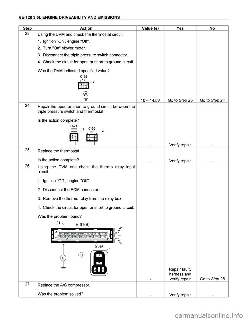
6E-128 3.5L ENGINE DRIVEABILITY AND EMISSIONS
Step Action Value (s) Yes No
23
Using the DVM and check the thermostat circuit.
1. Ignition "On", engine "Off".
2. Turn "On" blower motor.
3. Disconnect the triple pressure switch connector.
4. Check the circuit for open or short to ground circuit.
Was the DVM indicated specified value?
C-55
V
�
10 – 14.5V Go to Step 25 Go to Step 24
24
Repair the open or short to ground circuit between the
triple pressure switch and thermostat.
Is the action complete?
C-55C-24��
- Verify repair -
25
Replace the thermostat.
Is the action complete?
- Verify repair -
26
Using the DVM and check the thermo relay input
circuit.
1. Ignition "Off", engine "Off".
2. Disconnect the ECM connector.
3. Remove the thermo relay from the relay box.
4. Check the circuit for open or short to ground circuit.
Was the problem found?
E-61(B)
X-15
�
�
��
��
- Repair faulty
harness and
verify repair Go to Step 28
27
Replace the A/C compressor.
Was the problem solved?
- Verify repair -
Page 2148 of 4264
6E-152 3.5L ENGINE DRIVEABILITY AND EMISSIONS
Step Action Value (s) Yes No
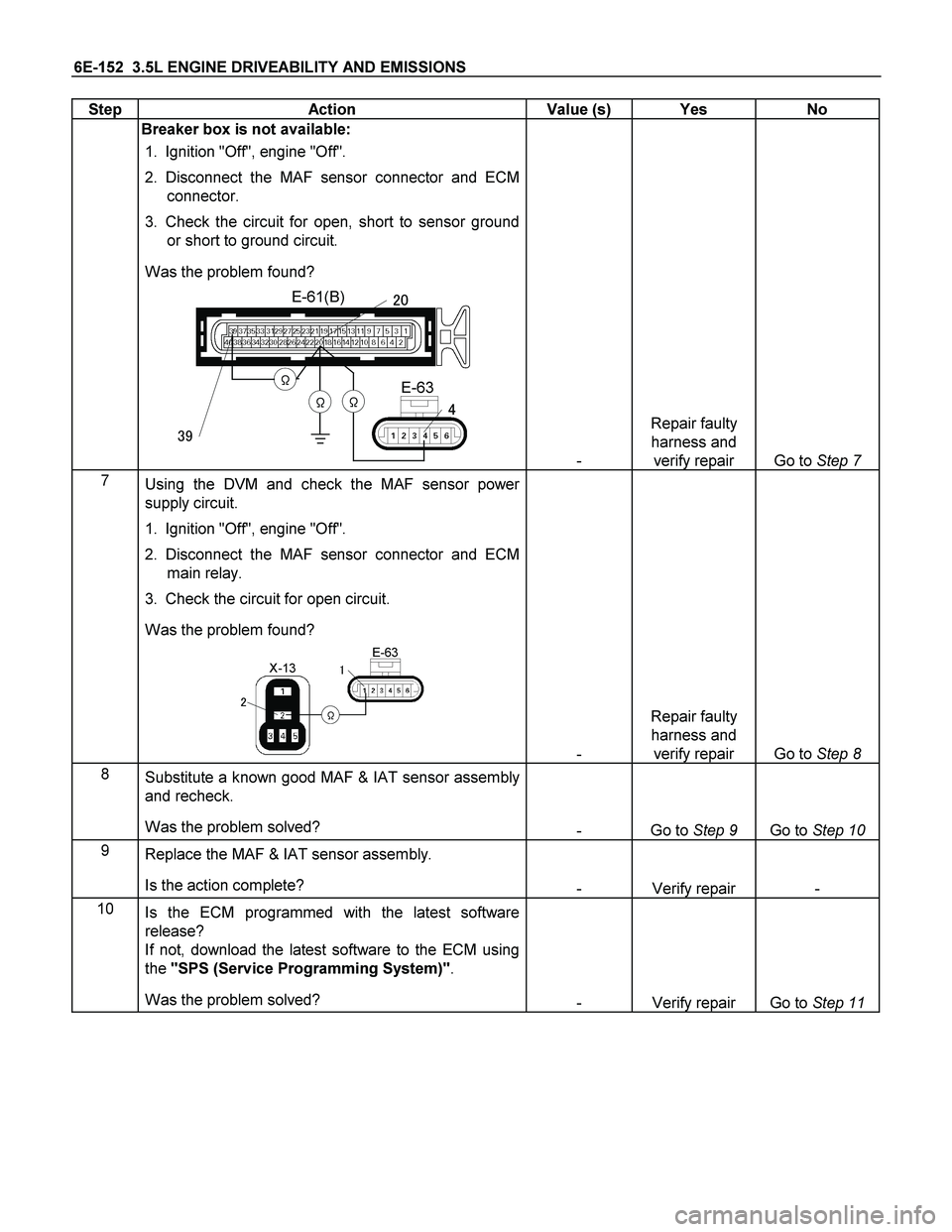
Breaker box is not available:
1. Ignition "Off", engine "Off".
2. Disconnect the MAF sensor connector and ECM
connector.
3. Check the circuit for open, short to sensor ground
or short to ground circuit.
Was the problem found?
E-61(B)
�
��E-63
�
��
��
- Repair faulty
harness and
verify repair Go to Step 7
7
Using the DVM and check the MAF sensor power
supply circuit.
1. Ignition "Off", engine "Off".
2. Disconnect the MAF sensor connector and ECM
main relay.
3. Check the circuit for open circuit.
Was the problem found?
�
X-13E-63
�
�
-
Repair faulty
harness and
verify repair
Go to Step 8
8
Substitute a known good MAF & IAT sensor assembly
and recheck.
Was the problem solved?
- Go to Step 9 Go to Step 10
9
Replace the MAF & IAT sensor assembly.
Is the action complete?
- Verify repair -
10
Is the ECM programmed with the latest software
release?
If not, download the latest software to the ECM using
the "SPS (Service Programming System)".
Was the problem solved?
- Verify repair Go to Step 11
Page 2206 of 4264
6E-210 3.5L ENGINE DRIVEABILITY AND EMISSIONS
Step Action Value (s) Yes No
7
Repair the open or short to ground circuit between the
fuel pump relay and O2 sensor heater for the affected
cylinder.
Was the problem found?
- Verify repair Go to Step 8
8
Repair the open circuit between the O2 sensor heater
and engine ground for the affected cylinder.
Was the problem found?
- Verify repair Go to Step 9
9
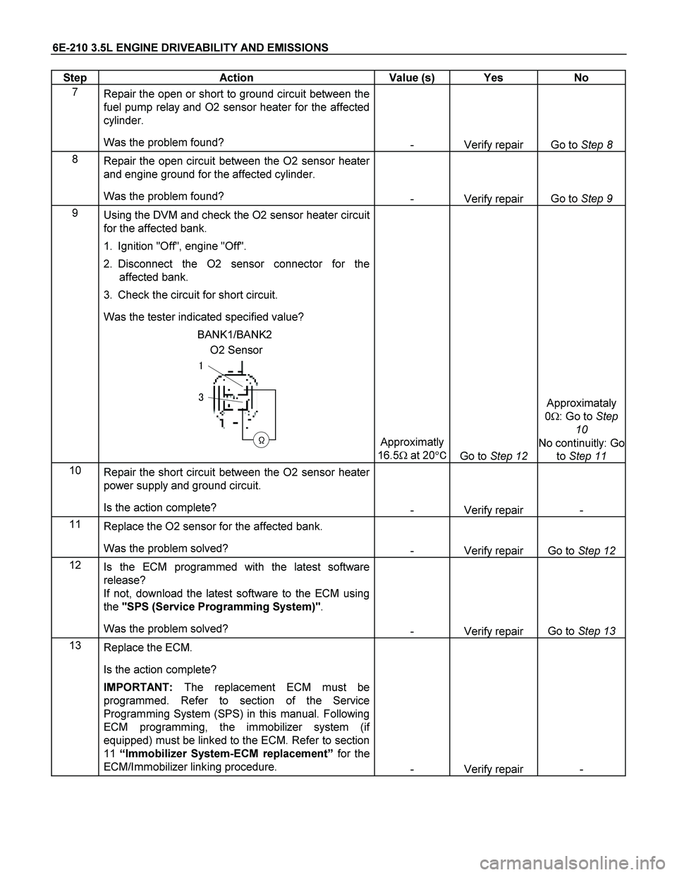
Using the DVM and check the O2 sensor heater circuit
for the affected bank.
1. Ignition "Off", engine "Off".
2. Disconnect the O2 sensor connector for the
affected bank.
3. Check the circuit for short circuit.
Was the tester indicated specified value?
O2 Sensor BANK1/BANK2
�
�
�
Approximatly
16.5� at 20��
Go to Step 12
Approximataly
0�: Go to Step
10
No continuitly: Go
to Step 11
10
Repair the short circuit between the O2 sensor heater
power supply and ground circuit.
Is the action complete?
- Verify repair -
11
Replace the O2 sensor for the affected bank.
Was the problem solved?
- Verify repair Go to Step 12
12
Is the ECM programmed with the latest software
release?
If not, download the latest software to the ECM using
the "SPS (Service Programming System)".
Was the problem solved?
- Verify repair Go to Step 13
13
Replace the ECM.
Is the action complete?
IMPORTANT: The replacement ECM must be
programmed. Refer to section of the Service
Programming System (SPS) in this manual. Following
ECM programming, the immobilizer system (if
equipped) must be linked to the ECM. Refer to section
11 “Immobilizer System-ECM replacement” for the
ECM/Immobilizer linking procedure.
- Verify repair -