Page 3138 of 4264
7B-20 MSG MODEL
REVERSE GEAR AND 5TH GEAR
Disassembly Steps
1. Bearing snap ring
2. Speedometer drive gear and lock ball
3. Bearing spacer
4. Mainshaft end ball bearing
5. Thrust ring snap ring
6. Thrust washer thrust ring
7. Thrust washer and lock ball
8. Counter reverse gear nut and washer
�
9. Counter end ball bearing
�
10. Counter 5th gear
11. Counter reverse gear
12. 5th gear
13. 5th block ring
14. Needle bearing
�
15. Mainshaft lock nut and washer
�
16. Rev. - 5th synchronizer assembly
17. Reverse gear
18. Needle bearing
19. Needle bearing collar
20. Thrust washer
21. Counter reverse gear lock nut
22. Thrust washer
23. Reverse idler gear
24. Thrust washer
25. Reverse idler shaft
�
26. Bearing snap ring
�
27. Bearing snap ring
�
28. Intermediate plate
Page 3139 of 4264

MSG MODEL 7B-21
Important Operations
9. Counter End Ball Bearing
10. Counter 5th Gear
Use the gear remover to remove the counter 5th gear with the
ball bearing.
Gear Remover : 5-8840-0013-0 (J-22888)
15. Mainshaft Lock Nut and Washer
1) Engage the 3rd - 4th synchronizer with the 3rd gear.
2) Engage the 1st - 2nd synchronizer with the 1st gear.
3) Attach the holding fixture to the mainshaft and the
countergear.
Holding Fixture : 5-8840-2001-0 (J-29768)
4) Use the lock nut wrench to remove the lock nut.
Lock Nut Wrench: 5-8840-0353-0 (J-36629)
16. Rev. - 5th Synchronizer Assembly
1) Remove the synchronizer assembly as a set.
2) Disassemble the synchronizer assembly.
1 Springs
2 Sleeve
3 Clutch Hub
4 Inserts
26. Bearing Snap Ring
1) Insert the snap ring pliers
1 into the counter gear bearing
snap ring hole
2.
The snap ring hole is in the intermediate plate
3.
2) Use the snap ring pliers to force open the counter gea
r
bearing snap ring.
Tap on the front of the intermediate plate.
The ball bearing snap ring will come free.
Page 3141 of 4264
MSG MODEL 7B-23
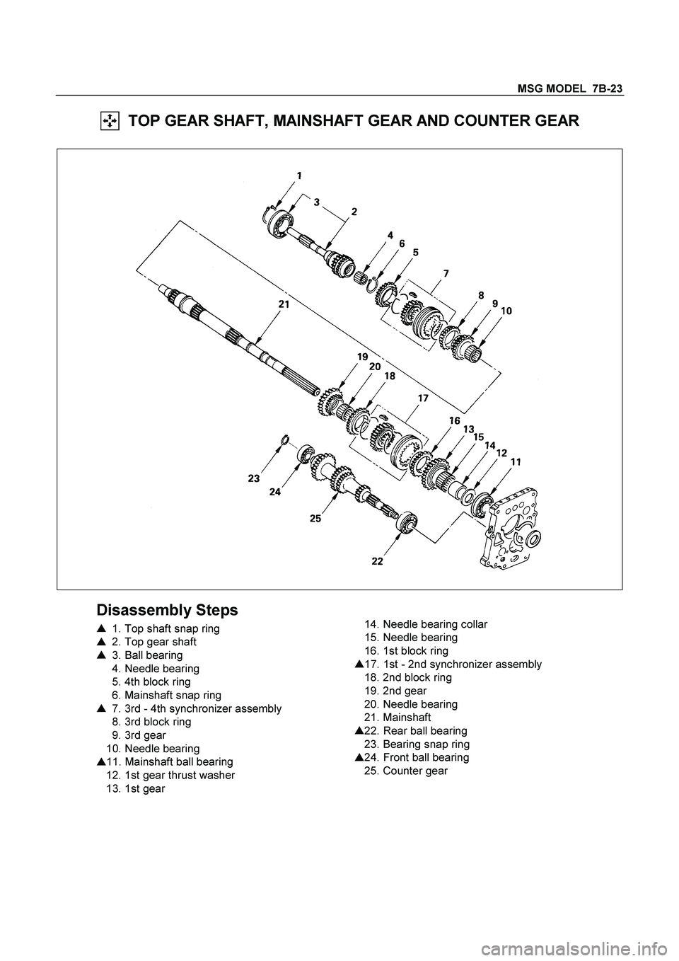
TOP GEAR SHAFT, MAINSHAFT GEAR AND COUNTER GEAR
Disassembly Steps
�
1. Top shaft snap ring
�
2. Top gear shaft
�
3. Ball bearing
4. Needle bearing
5. 4th block ring
6. Mainshaft snap ring
�
7. 3rd - 4th synchronizer assembly
8. 3rd block ring
9. 3rd gear
10. Needle bearing
�
11. Mainshaft ball bearing
12. 1st gear thrust washer
13. 1st gear
14. Needle bearing collar
15. Needle bearing
16. 1st block ring
�
17. 1st - 2nd synchronizer assembly
18. 2nd block ring
19. 2nd gear
20. Needle bearing
21. Mainshaft
�
22. Rear ball bearing
23. Bearing snap ring
�
24. Front ball bearing
25. Counter gear
Page 3143 of 4264

MSG MODEL 7B-25
INSPECTION AND REPAIR
Make the necessary adjustments, repairs, and part replacements if excessive wear or damage is discovered during
inspection.
SHIFT ARM THICKNESS
Use a micrometer to measure the shift arm thickness.
If the measured value is less than the specified limit, the shift
arm must be replaced.
Shift Arm Thickness mm(in)
Standard Limit
1st-2nd 9.6-9.8 (0.378-0.386) 9.0 (0.354)
3rd-4th 6.95-7.2 (0.273-0.283) 6.5 (0.256)
Rev.-5th 6.8-6.9 (0.268-0.272) 6.3 (0.248)
DETENT SPRING FREE LENGTH
Use a venier caliper to measure the detent spring free length.
If the measured value is less than the specified limit, the
detent spring must be replaced.
Detent Spring Free Length mm(in)
Standard Limit
25.6 (1.01) 23.6 (0.93)
DETENT SPRING TENSION
Use a spring tester to measure the valve spring tension.
If the measured value is less than the specified limit, the valve
spring must be replaced.
Valve Spring Tension N(kg/lb)
Compressed
Height mm(in)Standard Limit
22.1 (0.870)61.8-65.7
(6.3-6.7/13.9-14.8)55.9
(5.7/12.6)
BLOCK RING AND DOG TEETH
CLEARANCE
Use a thickness gauge to measure the clearance between the
block ring and the dog teeth.
If the measured value exceeds the specified limit, the block
ring must be replaced.
Block Ring and Dog Teeth Clearance mm(in)
Standard Limit
1st,2nd 2.0 (0.078) 1.3 (0.051)
3rd, 4th, 5th 1.5 (0.059) 0.8 (0.032)
Page 3144 of 4264

7B-26 MSG MODEL
BLOCK RING AND INSERT CLEARANCE
Use a thickness gauge to measure the clearance between the
block ring and the insert.
If the measured value exceeds the specified limit, the block
ring and the insert must be replaced.
Block Ring and Insert Clearance mm(in)
Standard Limit
1st,2nd 3.46-3.74 (0.136-0.147)
3rd, 4th, 5th 3.51-3.79 (0.138-0.149)4.0 (0.157)
CLUTCH HUB AND INSERT CLEARANCE
Use a thickness gauge to measure the clearance between the
clutch hub and the insert.
If the measured value exceeds the specified limit, the clutch
hub and the insert must be replaced.
Clutch Hub and Insert Clearance mm(in)
Standard Limit
0.01 - 0.19 (0.0004 - 0.0075) 0.3 (0.012)
MAINSHAFT RUN - OUT
1. Install the mainshaft to a grinding machine.
2. Use a dial indicator to measure the mainshaft central
portion run-out.
If the measured mainshaft run-out exceeds the specified
limit, the mainshaft must be replaced.
Mainshaft Run - Out mm(in)
Limit
Less than 0.03 (0.0012)
GEAR INSIDE DIAMETER
Use an inside dial indicator to measure the gear inside
diameter.
If the measured value is less than the specified limit, the gear
must be replaced.
Gear Inside Diameter mm(in)
Standard Limit
1st
Rev.45.00-45.01
(1.7717-1.7720)45.10 (1.7756)
2nd
3rd41.00-41.01
(1.6142-1.6146)41.10 (1.6181)
5th34.03-34.04
(1.3398-1.3402)34.10 (1.3425)
Page 3147 of 4264
MSG MODEL 7B-29
REASSEMBLY
MAJOR COMPONENT
INTERNAL PARTS
Reassembly steps
1. Top & main gear shaft assembly
2. Counter gear shaft assembly
3. Rev. and 5th gear assembly
4. Shift fork assembly & interlock pin
5. Detent assembly
Page 3148 of 4264
7B-30 MSG MODEL
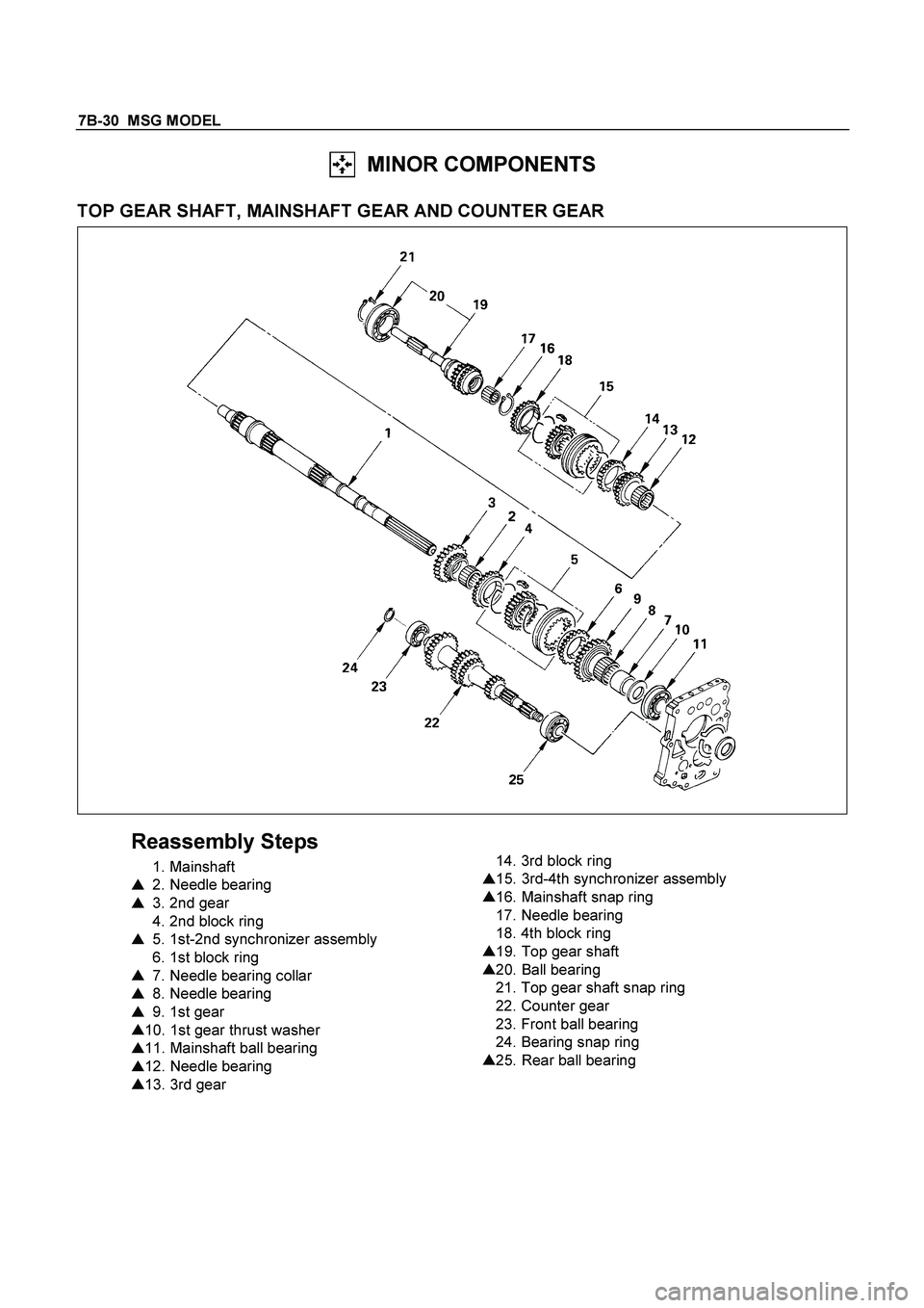
MINOR COMPONENTS
TOP GEAR SHAFT, MAINSHAFT GEAR AND COUNTER GEAR
Reassembly Steps
1. Mainshaft
�
2. Needle bearing
�
3. 2nd gear
4. 2nd block ring
�
5. 1st-2nd synchronizer assembly
6. 1st block ring
�
7. Needle bearing collar
�
8. Needle bearing
�
9. 1st gear
�
10. 1st gear thrust washer
�
11. Mainshaft ball bearing
�
12. Needle bearing
�
13. 3rd gear
14. 3rd block ring
�
15. 3rd-4th synchronizer assembly
�
16. Mainshaft snap ring
17. Needle bearing
18. 4th block ring
�
19. Top gear shaft
�
20. Ball bearing
21. Top gear shaft snap ring
22. Counter gear
23. Front ball bearing
24. Bearing snap ring
�
25. Rear ball bearing
Page 3152 of 4264
7B-34 MSG MODEL
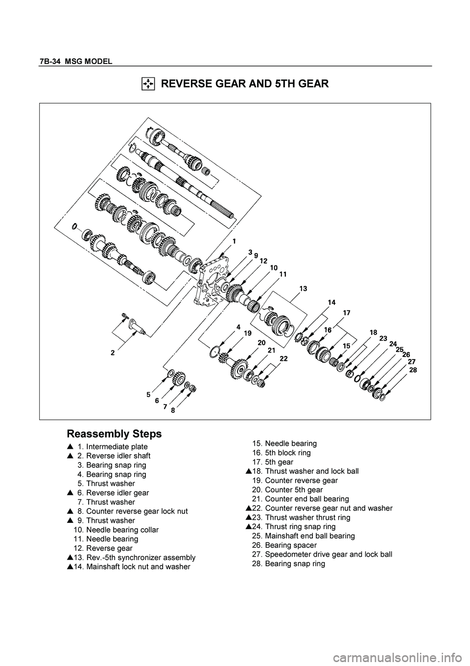
REVERSE GEAR AND 5TH GEAR
Reassembly Steps
�
1. Intermediate plate
�
2. Reverse idler shaft
3. Bearing snap ring
4. Bearing snap ring
5. Thrust washer
�
6. Reverse idler gear
7. Thrust washer
�
8. Counter reverse gear lock nut
�
9. Thrust washer
10. Needle bearing collar
11. Needle bearing
12. Reverse gear
�
13. Rev.-5th synchronizer assembly
�
14. Mainshaft lock nut and washer
15. Needle bearing
16. 5th block ring
17. 5th gear
�
18. Thrust washer and lock ball
19. Counter reverse gear
20. Counter 5th gear
21. Counter end ball bearing
�
22. Counter reverse gear nut and washer
�
23. Thrust washer thrust ring
�
24. Thrust ring snap ring
25. Mainshaft end ball bearing
26. Bearing spacer
27. Speedometer drive gear and lock ball
28. Bearing snap ring