Page 3197 of 4264
MANUAL TRANSMISSION 7B1-33
6. Mesh the 1st-2nd and 3rd-4th synchronizers with
both the 1st and 3rd gears (double engagement).
226RS015
This will prevent the mainshaft from turning.
7. Install the new mainshaft hub nut.
Use the mainshaft nut wrench 5-8840-2156-0 to
tighten the mainshaft nut (23) to the specified
torque.
Torque: 137 N�
�� �m (14 kg�
�� �m/101 lb�
�� �ft)
226RW214
8. Use a punch to stake the mainshaft nut (23).
226RW153
9. Install needle bearing (22), 5th block ring (21), and
5th gear (20).
10. Apply engine oil to the counter reverse gear (19) and
the reverse gear (26).
Install the counter reverse gear (19) to the counter
shaft.
The reverse gear projection must be facing the
intermediate plate.
226RW151
Page 3199 of 4264
 which will
provide the minimum clearance between the
intermediate plate (30) and the snap ring (10).
226RS022
�
Th")
MANUAL TRANSMISSION 7B1-35
14. Select reverse idler gear snap ring (10) which will
provide the minimum clearance between the
intermediate plate (30) and the snap ring (10).
226RS022
�
There are three snap ring sizes available.
The snap rings are color-coded to indicate their
thickness.
Intermediate Plate and Snap Ring Clearance
Standard: 0 - 0.15 mm (0 - 0.0059 in)
Snap Ring Availability
Thickness Color Coding
1.2 mm (0.047 in) White
1.3 mm (0.051 in) Yellow
1.4 mm (0.055 in) Blue
226RS021
�
Use a pair of snap ring pliers to install the snap
ring to the reverse idler shaft.
The snap ring must be fully inserted into the
reverse idler shaft snap ring groove.
15. Install thrust washer and lock ball (9) by performing
the following steps:
�
Use a thickness gauge to measure the
clearance between the 5th gear and the thrust
washer.
5th Gear and Thrust Washer Clearance
Standard: 0.10 - 0.25 mm (0.004 - 0.010 in))
� Measure clearance "A" as shown in the figure.
226RS023
�
Select appropriate thrust washer from chart.
�
There are four thrust washer sizes available.
Thrust Washer Availability
Thickness
mm (in) Color
CodingA mm (in) Clearance
mm (in)
7.9 (0.311) White 8.05 - 8.1
(0.317-0.319) 0.15 - 0.25
(0.006-0.010)
8.0 (0.315) Yellow8.1 - 8.2
(0.319-0.323) 0.1 - 0.25
(0.004-0.010)
8.1 (0.319) Green8.2 - 8.3
(0.323-0.327) 0.1 - 0.25
(0.004-0.010)
8.2 (0.323) Blue 8.3 - 8.36
(0.327-0.329) 0.1 - 0.21
(0.004-0.008)
�
The thrust washers are color coded to indicate
their thickness as shown in the figure.
Page 3200 of 4264
7B1-36 MANUAL TRANSMISSION
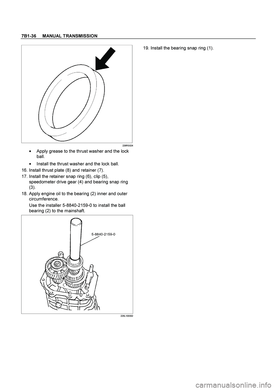
226RS024
�
Apply grease to the thrust washer and the lock
ball.
�
Install the thrust washer and the lock ball.
16. Install thrust plate (8) and retainer (7).
17. Install the retainer snap ring (6), clip (5),
speedometer drive gear (4) and bearing snap ring
(3).
18. Apply engine oil to the bearing (2) inner and outer
circumference.
Use the installer 5-8840-2159-0 to install the ball
bearing (2) to the mainshaft.
226L100002
19. Install the bearing snap ring (1).
Page 3202 of 4264
7B1-38 MANUAL TRANSMISSION
Legend
(1) Top Gear Shaft Snap Ring (16) 1st Outside Ring
(2) Top Gear Shaft (17) 1st Block Ring
(3) Ball Bearing (18) Needle Bearing
(4) Needle Bearing (19) Clutch Hub Snap Ring
(5) Top Block Ring (20) 1st-2nd Synchronizer Assembly
(6) Mainshaft Snap Ring (21) 2nd Block Ring
(7) 3rd-4th Synchronizer Assembly (22) 2nd Outside Ring
(8) 3rd Block Ring (23) 2nd Inside Ring
(9) 3rd Gear (24) 2nd Gear
(10) Needle Bearing (25) Needle Bearing
(11) Needle Bearing Collar (26) Mainshaft
(12) Mainshaft Ball Bearing (27) Bearing Snap Ring
(13) 1st Gear Thrust Bearing (28) Front Roller Bearing
(14) 1st Gear (29) Center Roller Bearing
(15) 1st Inside Ring (30) Counter Gear Shaft
Page 3203 of 4264
MANUAL TRANSMISSION 7B1-39
Disassembly
1. Use a pair of snap ring pliers to remove the top gear
shaft snap ring(1).
2. Remove top gear shaft(2) with ball bearing(3).
3. Use a bench press and the bearing remover 5-8840-
0015-0 to remove the ball bearing(3).
226RW216
4. Remove needle bearing (4) and top block ring (5),
mainshaft snap ring.
5. Use a pair of snap ring pliers to remove the
mainshaft snap ring (6).
226RS008
6. Use a bench press and the bearing remover 5-8840-
0015-0 to remove the 3rd-4th synchronizer
assembly (7) as a set.
Disassemble the synchronizer assembly.
226RW217
Legend
(1) Springs
(2) Sleeve
(3) Clutch Hub
(4) Inserts
7. Remove 3rd block ring (8), 3rd gear (9), and needle
bearing (10).
8. Use a bench press and the bearing remover 5-8840-
0015-0 to remove the 1st gear(14) together with the
mainshaft ball bearing(12), 1st gear thrust bearing
(13), and needle bearing collar (11).
226RW218
Page 3204 of 4264
7B1-40 MANUAL TRANSMISSION
9.Disassemble 1st inside ring (15), 1st outside ring (16),
and 1st block ring (17).
10.Remove needle bearing (18).
11.Use a pair of snap ring pliers to remove the clutch
hub snap ring (19).
226RS031
12.Use bench press and the bearing remover 5-8840-
0015-0 to remove the 2nd gear (24) together with
1st-2nd synchronizer assembly (20), 2nd block ring
(21), 2nd outside ring (22), and inside ring (23).
Disassemble the synchronizer assembly.
226RW220
Legend
(1) Springs
(2) Sleeve
(3) Clutch Hub
(4) Inserts
13. Remove needle bearing (25) from mainshaft (26).
14. Remove bearing snap ring (27).
15. Remove the front roller bearing (28) by performing
the following steps.
�
Remove the ring, outer race and bearing
assembly by using a bench press and remover
5-8840-0015-0.
� Remove the inner race by using a bench press
and remover 5-8840-0015-0.
226RW219
16. Remove center roller bearing (29) from counter gear
shaft (30).
Page 3205 of 4264
MANUAL TRANSMISSION 7B1-41
Inspection and Repair
Make the necessary adjustments, repairs, and part
replacements if excessive wear or damage is
discovered during inspection.
Block Ring and Dog Teeth Clearance
� Use a thickness gauge to measure the clearance
between the block ring and the dog teeth.
226RS035
If the measured value exceeds the specified limit,
the block ring must be replaced.
Block Ring and Dog Teeth Clearance
Standard Limit
1.5 mm (0.059 in) 0.8 mm (0.032 in)
Page 3206 of 4264

� Use a thickness gauge to measure the clearance
between the block ring and the dog teeth.
226RS036
If the measured value exceeds")
7B1-42 MANUAL TRANSMISSION
1st-2nd Synchronizer (3-CONE)
� Use a thickness gauge to measure the clearance
between the block ring and the dog teeth.
226RS036
If the measured value exceeds the specified limit,
the 1st-2nd synchronizer assembly must be
replaced.
Block Ring and Dog Teeth Clearance
Standard Limit
1.5 mm (0.059 in) 0.8 mm (0.032 in)
Block Ring and Insert Clearance
� Use a vernier caliper or thickness gauge to measure
the clearance between the block ring and the insert.
226RS037
If the measured value exceeds the specified limit,
the block ring and the insert must be replaced.
Block and Insert Clearance
Standard Limit
3rd-4th 3.46 - 3.76 mm
(0.136 - 0.148 in) 4.0 mm
(0.158 in)
1st-2nd3.86 – 4.16 mm
(0.152 - 0.164 in) 4.9 mm
(0.193 in)
Rev.5th3.59 - 3.91 mm
(0.141 - 0.154 in) 4.1 mm
(0.161 in)
Clutch Hub and Insert Clearance
�
Use a thickness gauge to measure the clearance
between the clutch hub and the insert.
226RS038
If the measured value exceeds the specified limit,
the clutch hub and the insert must be replaced.
Clutch Hub and Insert Clearance
Standard Limit
1st-2nd
3rd-4th 0.01 – 0.21 mm
(0.004 - 0.0083 in) 0.3 mm
(0.012 in)
Rev-5th0.09 – 0.31 mm
(0.0035 - 0.0122 in) 0.4 mm
(0.016 in)
.
226RS015
This will prevent the mainshaft from turning.
7.")
 Top Gear Shaft Snap Ring (16) 1st Outside Ring
(2) Top Gear Shaft (17) 1st Block Ring
(3) Ball Bearing (18) Needle Bearing
(4) Needle Bearing (")
.
2. Remove top gear shaft(2) with ball bearing(3).
3. Use a bench pre")
, 1st outside ring (16),
and 1st block ring (17).
10.Remove needle bearing (18).
11.Use a pair of snap ring pliers to remove the c")
