Page 3207 of 4264

MANUAL TRANSMISSION 7B1-43
Mainshaft Run-out
� Install the mainshaft to V-blocks.
�
Use a dial indicator to measure the mainshaft
central portion run-out.
226RS039
If the measured mainshaft run-out exceeds the
specified limit, the mainshaft must be replaced.
Mainshaft Run-out
Limit: 0.05 mm (0.0020 in)
Gear Inside Diameter
�
Use an inside dial indicator to measure the gear
inside diameter.
226RS040
If the measured value is less than the specified limit,
the gear must be replace.
Gear Inside Diameter
Standard Limit
1st
3rd 45.000 - 45.013 mm
(1.771 - 1.772 in) 45.100 mm
(1.776 in)
2nd 52.000 - 52.013 mm
(2.047 - 2.048 in) 52.100 mm
(2.051 in)
Rev. 48.000 - 48.013 mm
(1.889 - 1.890 in) 48.100 mm
(1.894 in)
5th 32.000 - 32.013 mm
(1.259 - 1.260 in) 32.100 mm
(1.246 in)
Reverse Idler Gear and Idler Gear Shaft
Clearance
�
Use a micrometer to measure the idler gear shaft
diameter.
� Use an inside dial indicator to measure the idler
gear inside diameter.
226RS041
�
Calculate the idler gear and idler gear shaft
clearance.
Idler gear inside diameter-idler gear shaft diameter =
idle gear and idler gear shaft clearance.
If the measured value exceeds the specified limit,
the idle gear and/or the idler gear shaft must be
replaced
Idler Gear and Idler Gear Shaft Clearance
Standard: 0.041 - 0.074 mm (0.0016 -0.0029 in)
Limit: 0.150 mm (0.0059 in)
Page 3209 of 4264
 Ring
(2) Outer Race and Roller Assembly
(3) Inner Race
3. Instal")
MANUAL TRANSMISSION 7B1-45
�
Use bearing installer 5-8840-2194-0 to install the
ring.
RTW47BSH000501
Legend
(1) Ring
(2) Outer Race and Roller Assembly
(3) Inner Race
3. Install bearing snap ring (27) to counter gear shaft
(30).
4. Apply engine oil to the needle bearing (25) and the
2nd gear (24) thrust surfaces.
Install the needle bearing (25) and the 2nd gear (24)
to the mainshaft (26).
The 2nd gear (24) dog teeth must be facing the
transmission rear side.
226RS046
5. Assemble 2nd inside ring (23), 2nd outside ring (22),
and 2nd block ring (21) on 2nd gear (24).
�
Apply engine oil to the synchronizer ring friction
surfaces.
226RS047
Legend
(1) Block Ring
(2) Outside Ring
(3) Inside Ring
(4) 2nd Gear
(5) Needle Bearing
6. Assemble 1st-2nd synchronizer assembly (20) by
performing the following steps:
1. Check that the inserts (3) fit snugly into the
clutch hub (5) insert grooves.
2. Check that the inserts springs (4) are fitted to
the inserts as shown in the illustration.
3. Check that the clutch hub (5) and the sleeve (6)
slide smoothly.
Page 3211 of 4264
MANUAL TRANSMISSION 7B1-47
226RS031
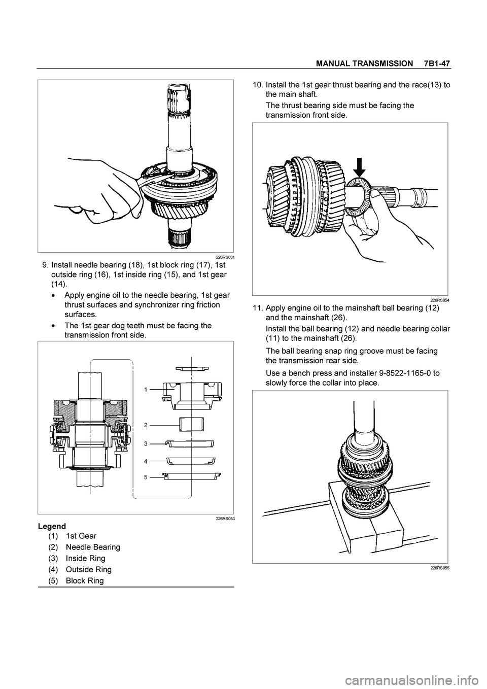
9. Install needle bearing (18), 1st block ring (17), 1st
outside ring (16), 1st inside ring (15), and 1st gear
(14).
�
Apply engine oil to the needle bearing, 1st gear
thrust surfaces and synchronizer ring friction
surfaces.
�
The 1st gear dog teeth must be facing the
transmission front side.
226RS053
Legend
(1) 1st Gear
(2) Needle Bearing
(3) Inside Ring
(4) Outside Ring
(5) Block Ring
10. Install the 1st gear thrust bearing and the race(13) to
the main shaft.
The thrust bearing side must be facing the
transmission front side.
226RS054
11. Apply engine oil to the mainshaft ball bearing (12)
and the mainshaft (26).
Install the ball bearing (12) and needle bearing collar
(11) to the mainshaft (26).
The ball bearing snap ring groove must be facing
the transmission rear side.
Use a bench press and installer 9-8522-1165-0 to
slowly force the collar into place.
226RS055
Page 3212 of 4264
 and the
3rd gear (9) thrust surfaces.
Install the needle bearing (10) and the 3rd gear (9)
to the mainshaft.
The 3")
7B1-48 MANUAL TRANSMISSION
12. Apply engine oil to the needle bearing (10) and the
3rd gear (9) thrust surfaces.
Install the needle bearing (10) and the 3rd gear (9)
to the mainshaft.
The 3rd gear dog teeth must be facing the
transmission front side.
226RS056
13. Install 3rd block ring (8).
14. Check and install 3rd-4th synchronizer assembly (7)
by the following steps:
1. Check that the inserts (3) fit snugly into the
clutch hub insert grooves.
2. Check that the insert springs (4) are fitted to the
inserts as shown in the illustration.
3. Check that the clutch hub (5) and the sleeve (6)
slide smoothly.
4. Install the synchronizer assembly to the
mainshaft.
The clutch hub face with the heavy boss must be
facing the 3rd gear side.
226RW221
226RS049
15. Select and install mainshaft snap ring(6) in the
following way:
Select the snap ring which will provide the minimum
clearance between the 3rd-4th clutch hub and the
snap ring.
226RS058
There are three snap ring sizes available.
The snap rings are color coded to indicate their
thickness as shown in the figure.
Page 3213 of 4264
MANUAL TRANSMISSION 7B1-49
226RS021
Clutch Hub and Snap Ring Clearance
Standard: 0 - 0.1 mm (0 - 0.004 in)
Snap Ring Availability
Thickness Color Coding
1.80 mm (0.071 in) White
1.85 mm (0.073 in) Yellow
1.90 mm (0.075 in) Blue
�
Use a pair of snap ring pliers to install the snap
ring to the mainshaft.
The snap ring must be fully inserted into the
mainshaft snap ring groove.
16. Install top block ring (5).
Apply grease to the needle bearing (4) inner and
outer circumferences and install needle bearing (4)
in the top gear shaft (2).
17. Use a bench press to install the top gear shaft ball
bearing (3) to the top gear shaft (2).
226RS059
The snap ring groove of the ball bearing (3) must be
facing the transmission front side.
18. Use a pair of snap ring pliers to install the top gear
shaft snap ring (1) to the top gear shaft (2).
Page 3220 of 4264
7B1-56 MANUAL TRANSMISSION
2. HARD SHIFTING
Checkpoint Trouble Cause Countermeasure
Change lever play
Clutch pedal free play
Repair or replace the
applicable parts and regrease
Readjust the clutch pedal free
play
Worn change lever sliding
portions
Improper clutch pedal free
play
Change lever operationRepair or regrease the change
lever assembly
Replenish or replace the
engine oil
Hard operating change lever
caused insufficient grease
Insufficient or improper gear
oil
OK
OKNG NG NG NG
OK OKGear oil
Continued on the next page
Shift rod and quadrant box
sliding faces, and other partsReplace the shidt rod and/or
the quadrant boxWorn shift rod and/or sliding
faces
Repair or replace the sleeveSleeve movement failure
NG NG
OKShift block sleeve movement
Page 3226 of 4264
. REFER TO THE SRS
COMPONENT AND WIRING LOCATION VIEW IN
ORDER TO DETERMINE WHET")
7B1-62 MANUAL TRANSMISSION
Service Precaution
WARNING: THIS VEHICLE HAS A SUPPLEMENTAL
RESTRAINT SYSTEM (SRS). REFER TO THE SRS
COMPONENT AND WIRING LOCATION VIEW IN
ORDER TO DETERMINE WHETHER YOU ARE
PERFORMING SERVICE ON OR NEAR THE SRS
COMPONENTS OR THE SRS WIRING. WHEN YOU
ARE PERFORMING SERVICE ON OR NEAR THE
SRS COMPONENTS OR THE SRS WIRING, REFER
TO THE SRS SERVICE INFORMATION. FAILURE TO
FOLLOW WARNINGS COULD RESULT IN POSSIBLE
AIR BAG DEPLOYMENT, PERSONAL INJURY, OR
OTHERWISE UNNEEDED SRS SYSTEM REPAIRS. CAUTION: Always use the correct fastener in the
proper location. When you replace a fastener, use
ONLY the exact part number for that application.
ISUZU will call out those fasteners that require a
replacement after removal. ISUZU will also call out
the fasteners that require thread lockers or thread
sealant. UNLESS OTHERWISE SPECIFIED, do not
use supplemental coatings (Paints, greases, or
other corrosion inhibitors) on threaded fasteners or
fastener joint interfaces. Generally, such coatings
adversely affect the fastener torque and the joint
clamping force, and may damage the fastener.
When you install fasteners, use the correct
tightening sequence and specifications. Following
these instructions can help you avoid damage to
parts and systems.
Page 3245 of 4264
MANUAL TRANSMISSION 7B1-81
Intermediate Plate with Gear Assembly, Detent, Shift Arm, Shift Rod, and
Interlock Pin
Disassembled View
RTW47BLF000501
Legend
(1) Detent Spring Plate and Gasket (7) 1st-2nd Shift Rod
(2) Detent Spring (8) 3rd-4th Shift Rod
(3) Detent Ball (9) 3rd-4th Shift Arm
(4) Spring (10) 1st-2nd Shift Arm
(5) Rev-5th Shift Rod (11) Interlock Pin
(6) Rev-5th Shift Arm and Reverse Inhibitor (12) Intermediate Plate and Gear Assembly

Snap Ring Availability
Thickness Color Coding
1.80 mm (0.071 in) White
1.85")

 Detent Spring Plate a")