Page 3050 of 4264
1-40 HEATER AND AIR CONDITIONING
COMPRESSOR
REMOVAL AND INSTALLATION (4J ENGINE)
852R300006
Removal Steps
1. Air duct
2. Magnetic clutch harness connector
3. Lock nut
4. Tension adjustment bolt
5. Drive belt
6. Refrigerant line
7. Bolt; compressor to bracket
8. Compressor assembly
Installation Steps
8. Compressor assembly
� 7. Bolt; compressor to bracket
� 6. Refrigerant line
5. Drive belt
4. Tension adjustment bolt
3. Lock nut
2. Magnetic clutch harness connector
1. Air duct
Page 3085 of 4264
HEATER AND AIR CONDITIONING 1-75
Important Operation - Removal
1. Control lever assembly
Refer to “CONTROL LEVER ASSEMBLY” in this section.
2. Illumination Bulb
To remove the illumination bulb, insert an ordinary screwdriver
into the slot (B) at the back of the bulb. Turn the bulb
counterclockwise and pull it free.
Page 3096 of 4264

pres-sure
abnormally
low
Condenser is not hot and
excessive bubble in sight glass
��
Insuf")
1-86 HEATER AND AIR CONDITIONING
RESULT SYMPTOM TROUBLE CAUSE CORRECTION
Suction
(Low)
pres-sure
abnormally
low
Condenser is not hot and
excessive bubble in sight glass
��
Insufficient refrigerant
��
Check sight
glass.(See “Reading
Sight Glass”)
��
Check for leaks
��
Discharge and
recover refrigerant.
Recharge to specified
amount
Frost on the expansion valve inlet
line ��
Expansion valve clogged
��
Replace the
expansion valve
A distinct difference in
temperature between the inlet and
outlet refrigerant lines of the
receiver/drier ��
Receiver/drier clogged
��
Replace the receiver/
drier
Expansion valve outlet refrigerant
line is not cold and low-pressure
gauge indicates vacuum
��
The temperature sensor of
the expansion valve is
defective, and the valve
cannot regulate the correct
flow of the refrigerant ��
Replace the
expansion valve
Discharge temperature is low and
air flow from vents is restricted
��Frozen evaporator core fins
��Check electronic
thermostat and
replace as necessary
Low-pressure gauge reading is
low, or a vacuum reading may be
shown ��
Clogged or blocked
refrigerant line
��
Replace refrigerant
line
Suction
(Low) and
Discharge
(High)
pressure
abnor-
mally
high
No bubbles in sight glass after
condenser is cooled by water
(Insufficient cooling)
��
Excessive refrigerant in
system
��
Check sight
glass.(See “Reading
Sight Glass”)
��
Discharge and
recover refrigerant.
Recharge to specified
amount
Reduce air flow through con-
denser
��
Condenser clogged
��Radiator (condenser) fan
does not rotate properly ��
Clean
��Check cooling fan
operation
Suction (Low) pressure hose is
not cold ��
Air in system ��
Evacuate and charge
refrigerant
Suction
(Low) and
Discharge
(High)
pres-sure
abnor-
mally
low
Insufficient cooling and excessive
bubbles in the sight glass ��
Insufficient refrigerant in
system
��
Check sight glass.
(See “Reading Sight
Glass”)
��
Check for leaks
��Discharge and
recover refrigerant.
Recharge to specified
amount
Page 3121 of 4264
MSG MODEL 7B-3
GENERAL DESCRIPTION
The MSG type transmission is fully synchronized 5-speed unit with blocking ring type synchronizers and a constant
mesh type reverse gear.
The unit consists principally of a case with an integral clutch housing, intermediate plate, rear cover and gears.
The top of the rear cover is a quadrant box containing the transmission control mechanism.
The case and rear cover are cast aluminum alloy to reduce weight.
Page 3133 of 4264
MSG MODEL 7B-15
DISASSEMBLY
MAJOR COMPONENTS
RTW47BLF000301
Disassembly Steps
1. Clutch shift block and release bearing
2. Clutch shift fork
3. Speedometer sensor
4. Speedometer driven gear assembly
5. Gear control box assembly
�
6. Front cover with oil seal
�
7. Counter gear snap ring
�
8. Bearing snap ring
9. Rear cover with oil seal
10. Transmission case
11. Intermediate plate with gear assembly
Page 3135 of 4264
MSG MODEL 7B-17
MAJOR COMPONENT
INTERNAL PARTS
Disassembly steps
1. Detent assembly
2. Shift fork assembly & interlock pin
3. Rev. and 5th gear assembly
4. Counter gear shaft assembly
5. Top & main gear shaft assembly
Page 3136 of 4264
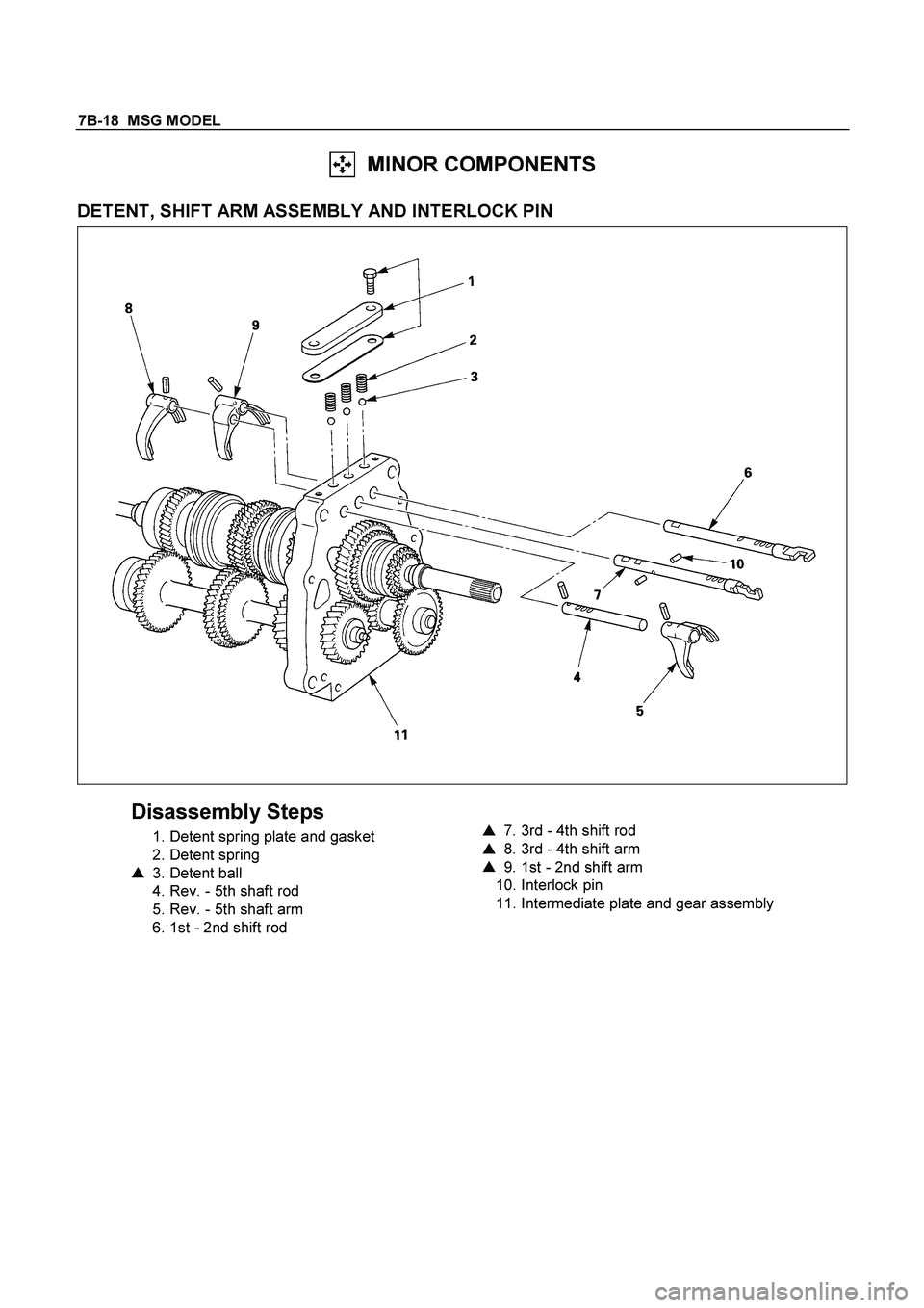
7B-18 MSG MODEL
MINOR COMPONENTS
DETENT, SHIFT ARM ASSEMBLY AND INTERLOCK PIN
Disassembly Steps
1. Detent spring plate and gasket
2. Detent spring
�
3. Detent ball
4. Rev. - 5th shaft rod
5. Rev. - 5th shaft arm
6. 1st - 2nd shift rod
�
7. 3rd - 4th shift rod
�
8. 3rd - 4th shift arm
�
9. 1st - 2nd shift arm
10. Interlock pin
11. Intermediate plate and gear assembly
Page 3137 of 4264
MSG MODEL 7B-19
Important Operations
3. Detent Ball
7. 3rd - 4th Shift Rod
8. 3rd - 4th Shift Arm
9. 1st - 2nd Shift Arm
1) Hold a round bar against the shift arm end.
This will prevent damage to other components.
2) Use a spring pin remover to remove the shift arm spring pin
from the shift arm and the shift rod.
Spring Pin Remover : 9-8529-2201-0
Discard the used spring pin.
3) Move the 3rd - 4th shift rod forward.
Take care not to lose the interlock pins.

852R300006
Removal Steps
1. Air duct
2. Magnetic clutch harness connector
3. Lock nut")


 Hold a round bar against the shift arm end.
Thi")