Page 3428 of 4264

3A-12 FRONT ALIGNMENT
Toe-in Adjustment
Measurement should be taken with the vehicle on a surface
plate.
If a surface plate is not available, toe-in should be checked
with the vehicle parked on a level floor.
1. Set front wheels to straight ahead position.
2. Align the toe-in gauge with center height of each wheel a
t
front end.
3.
Apply center marks to each wheel, then take measurement
of distance A between the center marks on each wheel.
4. Slowly move the vehicle rearward until the center marks
reach the rear end position.
5. Take measurement of distance B between the cente
r
marks at rear end.
The toe-in can be calculated with next formula.
Toe-in = B - A
Toe-in mm (in)
4�2 (High ride suspension)
4�4 0�2 (0�0.08)
To adjust the toe-in angle, loosen the lock nuts (2) on the tie
rod (1) and turn the tie rod. Turn both rods the same amount,
to keep the steering wheel centered.
Lock Nut Torque N�
m (kgf�
m/lb�
ft)
98�6.0 (10.0�0.6 / 72.3�4.3)
RTW330SH000201
Trim Height
Trim Height : at Curb Weight
Trim height (Z) = A - B
mm (in)
Z
140�
5 (5.51)
Page 3429 of 4264
FRONT ALIGNMENT 3A-13
450R100002-X
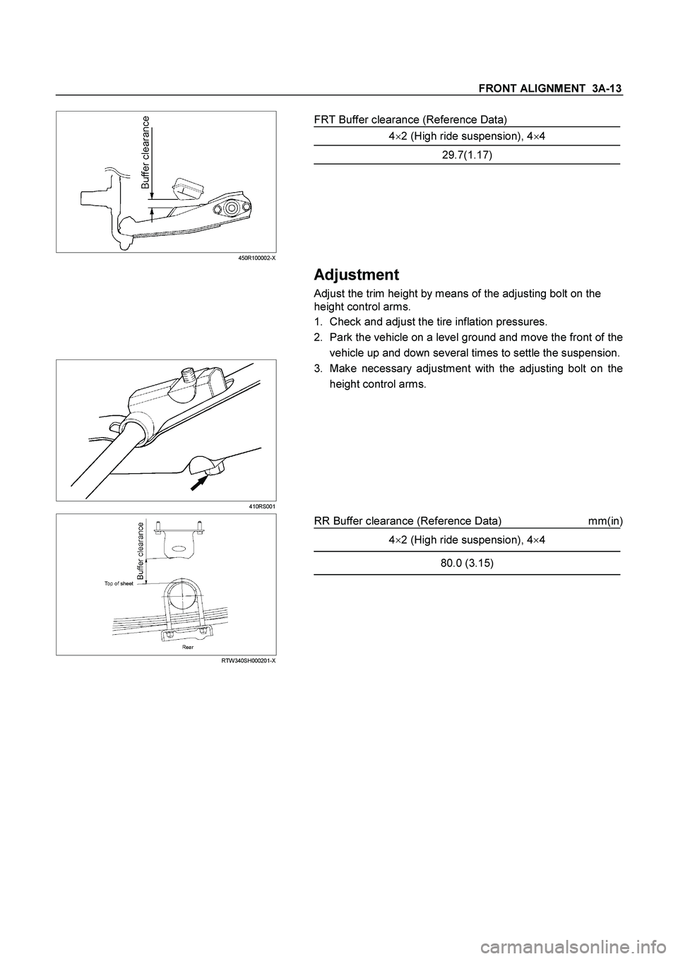
FRT Buffer clearance (Reference Data)
4�2 (High ride suspension), 4�4
29.7(1.17)
Adjustment
Adjust the trim height by means of the adjusting bolt on the
height control arms.
1. Check and adjust the tire inflation pressures.
2. Park the vehicle on a level ground and move the front of the
vehicle up and down several times to settle the suspension.
410RS001
3. Make necessary adjustment with the adjusting bolt on the
height control arms.
RTW340SH000201-X
RR Buffer clearance (Reference Data) mm(in)
4�
2 (High ride suspension), 4�
4
80.0 (3.15)
Page 3499 of 4264
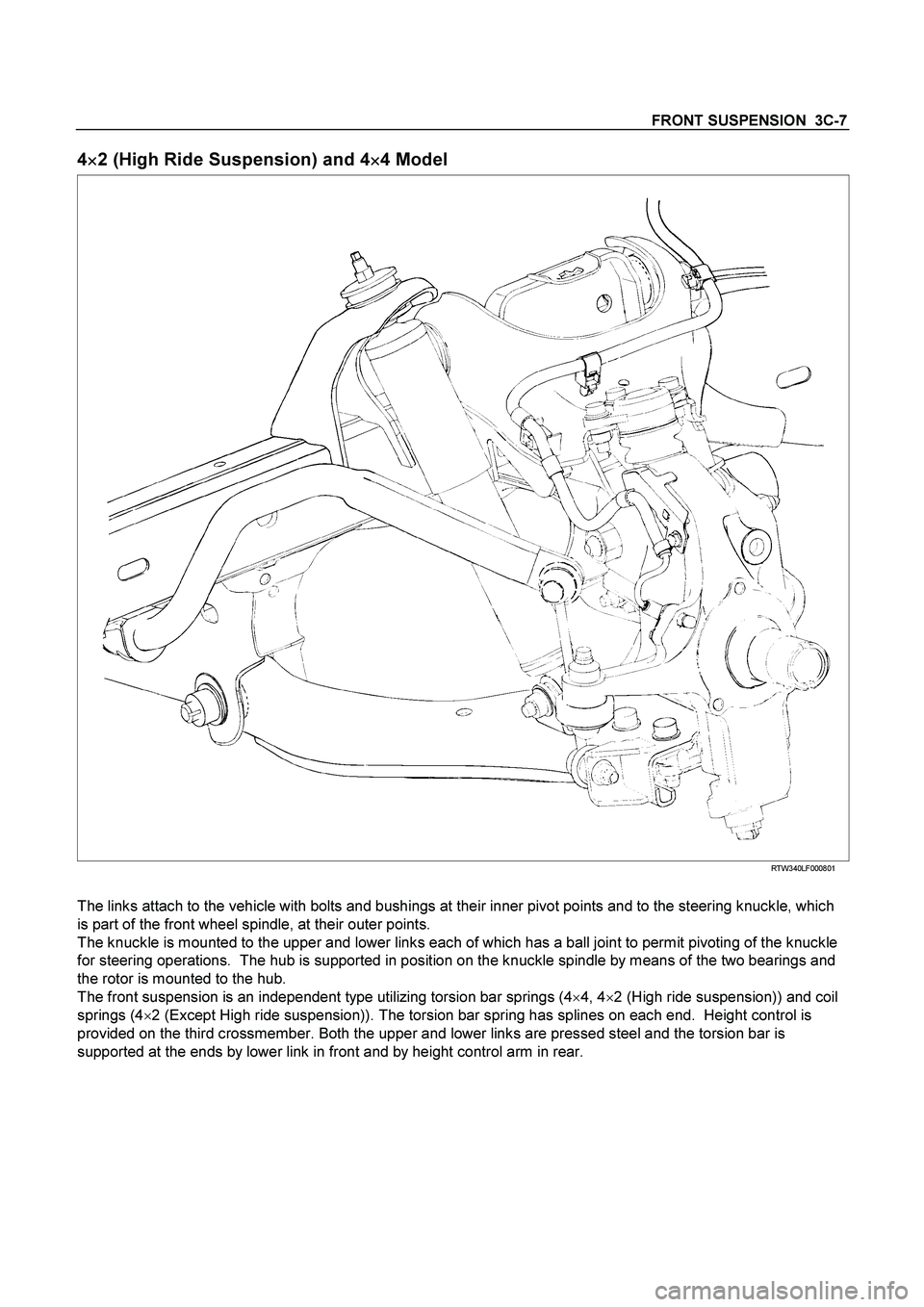
FRONT SUSPENSION 3C-7
4
�
�� �2 (High Ride Suspension) and 4
�
�� �4 Model
RTW340LF000801
The links attach to the vehicle with bolts and bushings at their inner pivot points and to the steering knuckle, which
is part of the front wheel spindle, at their outer points.
The knuckle is mounted to the upper and lower links each of which has a ball joint to permit pivoting of the knuckle
for steering operations. The hub is supported in position on the knuckle spindle by means of the two bearings and
the rotor is mounted to the hub.
The front suspension is an independent type utilizing torsion bar springs (4�
4, 4�
2 (High ride suspension)) and coil
springs (4�
2 (Except High ride suspension)). The torsion bar spring has splines on each end. Height control is
provided on the third crossmember. Both the upper and lower links are pressed steel and the torsion bar is
supported at the ends by lower link in front and by height control arm in rear.
Page 3503 of 4264
, then tighten it to the specified
torque.
Torque: 55N
�
�� �m (5.6kg
�
�� �m/41lb ft)
3.")
FRONT SUSPENSION 3C-11
NOTE: Paint mark to be outer side of after assembly to
vehicle.
2. Install nut (2), then tighten it to the specified
torque.
Torque: 55N
�
�� �m (5.6kg
�
�� �m/41lb ft)
3. Install bolt (7) and nut (4), then tighten to the
specified torque.
Buffer clearance: 25.9 mm (1.02 in)
Torque: 137N�
�� �m (14.0kg�
�� �m/101 lb ft)
NOTE: Apply oil to the thread.
NOTE: Tighten the bolt and nut with the parts in the
position shown in the illustration below.
RTW340SH001301-X
4. Install nut (6), then tighten it to the specified
torque.
Torque: 50N�
�� �m (5.1kg�
�� �m/37 lb ft)
5. Tighten the cam bolt (8) and nut (3), it to the
interim torque, then turn the cam bolt to the setting
mark applied during disassembly.
6. Install ball joint nut, then tighten it to the specified
torque with just enough additional torque to align
cotter pin holes. Install new cotter pin (5).
Torque: 147N�
�� �m (15.0kg�
�� �m/108 lb ft)
NOTE: Check the trim height. Refer to Front Alignment
Inspection and Adjustment.
7. Nut (3) tighten it to the specified torque.
Buffer clearance: 25.9 mm (1.02 in)
Torque: 186N�
�� �m (19.0kg�
�� �m/137 lb ft)
NOTE: Apply oil to the thread.
NOTE: Tighten the bolt and nut with the parts in the
position shown in the illustration below.
RTW340SH001301-X
8. Install wheel and tire assembly. Refer to wheel in
this section.
Page 3526 of 4264
3C-34 FRONT SUSPENSION
Torsion Bar
Torsion Bar and Associated Parts
RTW340MF000501
Legend
(1)
Adjust Bolt, End Piece and Seat
(2)
Height Control Arm
(3) Torsion Bar
Removal
1. Raise the vehicle and support the frame with
suitable safety stands.
2. Apply the setting marks (1) to the adjust bolt and end piece, then remove adjust bolt, end piece and
seat.
410RS004
Page 3527 of 4264
FRONT SUSPENSION 3C-35
3. Apply the setting marks(2) to the height control
arm and torsion bar, then remove height control
arm.
NOTE: “Besco chassis grease” shall be applied on
contact area of height control arm with frame.
(RH & LH Both side)
410RS005
4. Apply the setting marks (3) to the torsion bar and
lower control arm, then remove torsion bar.
RTW340SH000301
Inspection and Repair
Make necessary correction or parts replacement if
wear, damage, corrosion or any other abnormal
condition are found through inspection.
Check the following parts:
� Torsion bar
�
Height control arm
�
Adjust bolt
Installation
1. Apply grease to the serrated portions, then install
torsion bar. Make sure the bars are on their correct
respective sides and align the setting marks (3).
410RS007
RTW340SH000301
Page 3528 of 4264
3C-36 FRONT SUSPENSION
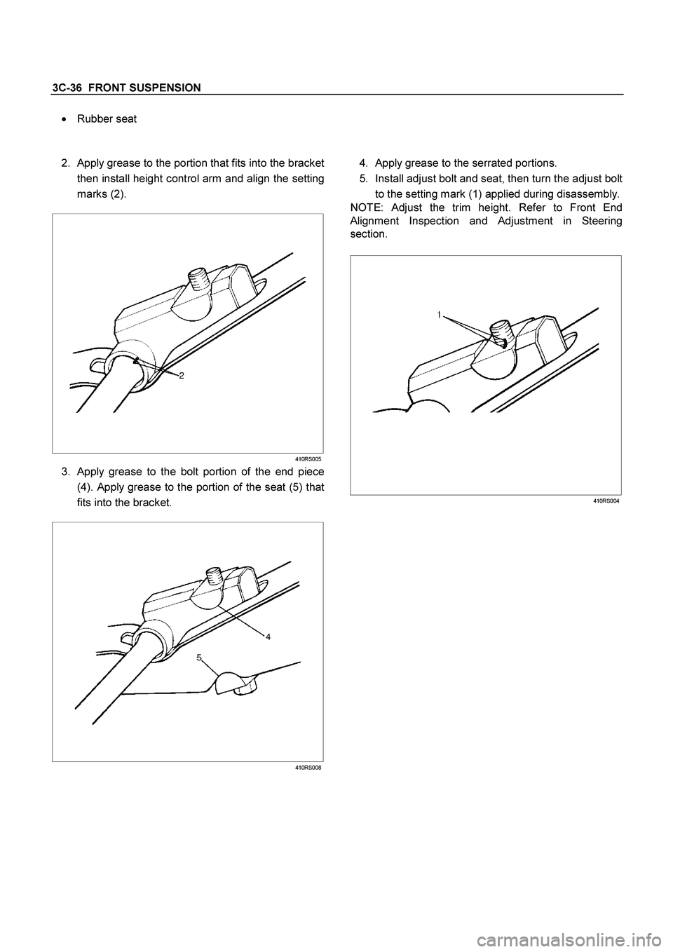
� Rubber seat
2.
Apply grease to the portion that fits into the bracket
then install height control arm and align the setting
marks (2).
410RS005
3. Apply grease to the bolt portion of the end piece
(4). Apply grease to the portion of the seat (5) that
fits into the bracket.
410RS008
4. Apply grease to the serrated portions.
5. Install adjust bolt and seat, then turn the adjust bolt
to the setting mark (1) applied during disassembly.
NOTE: Adjust the trim height. Refer to Front End
Alignment Inspection and Adjustment in Steering
section.
410RS004
Page 3530 of 4264
3C-38 FRONT SUSPENSION
4. Remove the hub assembly. Refer to Front Hub
and Disk in this section.
5. Remove tie-rod end from the knuckle. Refer to
Power Steering Unit in Steering section.
6. Remove the speed sensor from the knuckle.
7. Loosen torsion bar by height control arm adjust
bolt, then remove torsion bar. Refer to Torsion Ba
r
in this section.
8. Remove speed sensor harness.
9. Remove back plate.
10. Remove lower ball joint by using remover 5-8840-
2005-0.
CAUTION: Be careful not to damage the ball joint
boot.
901RW271
11. Remove upper ball joint by using remover 5-8840-
2121-0.
CAUTION: Be careful not to damage the ball joint
boot.
901RW272
12. Remove knuckle assembly.
13. Remove oil seal. If replacement required.
(4�
4 Model Only)
14. Remove washer. If replacement required.
(4�
4 Model Only)
15. Remove needle bearing by using remover 5-8840-
2000-0 and sliding hammer 5-8840-0019-0.
If replacement required. (4�
4 Model Only)
(4�
4 Model Only)
RTW340SH00401

Adjust Bolt, End Piece and Seat
(2)
Height Control Arm
(3) Tors")
 to the height control
arm and torsion bar, then remove height control
arm.
NOTE: “Besco chassis grease” shall be applied on
contact area of")