Page 2506 of 4264
6A-86 ENGINE MECHANICAL (C24SE)
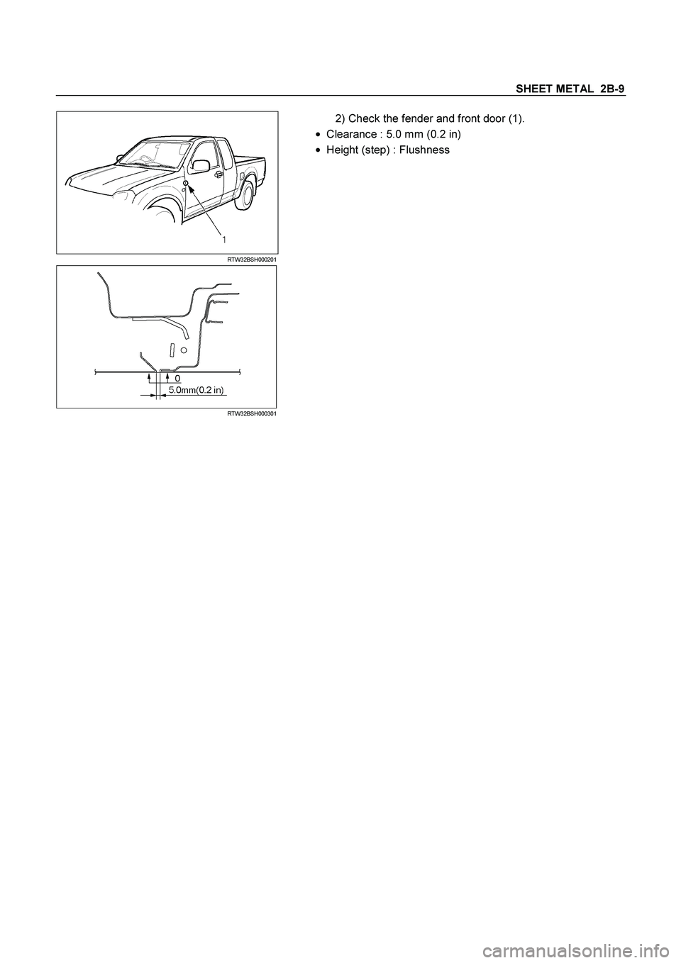
Crankshaft, Cylinder Block (continued)
Flywheel
Starter ring gear Before fitting, heat ring gear to 180�C -
230�C
Lateral run-out Permissible lateral run-out of installed
starter ring gear to flywheel: 0.5mm
Precision turning Permissible removal of material in clutch
disc lining surface area: 0.3mm
In order to achieve the functional
relationship again after removal of material,
the same removal of material must take
place on the fore part of the flywheel
(contact for clutch assembly)
Dimension A: 2.1 to 2.2mm
Cylinder block
Top deck flatness mm 0.05
Cylinder block height mm 271�0.075
Page 2935 of 4264
SHEET METAL 2B-3
Important Operations - Removal
1. Washer Nozzle Tube
1) Open the hood.
2) Support the hood.
3) Remove the windshield washer nozzle tube.
2. Hood Hinge Bolts
�
Before removing
the hinges from the engine hood, scribe a
mark showing location of
the hinges to facilitate installation in
the original position.
RTW32BSH000101
Important Operations - Installation
3. Engine Hood
�
Check the engine hood and fender. (1)
�
Clearance : 4.0 mm (0.16 in)
�
Height (step) : Flushness
�
Adjust clearance with the hinges on the engine hood.
�
Adjust height (step) with the hood rests (1).
Engine Hood Striker
�
Apply a light coat of grease to the striker.
Page 2941 of 4264
SHEET METAL 2B-9
RTW32BSH000201
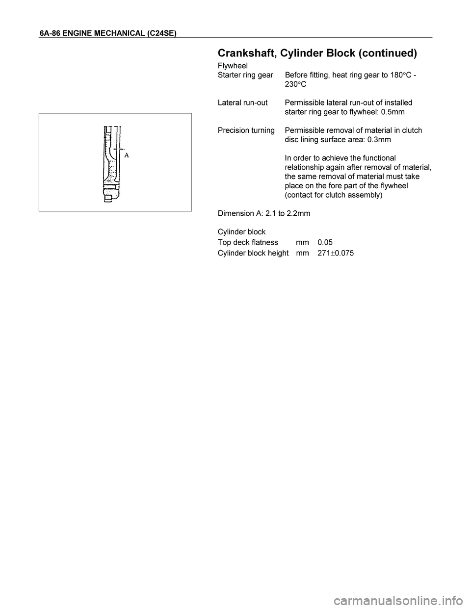
2) Check the fender and front door (1).
�
Clearance : 5.0 mm (0.2 in)
�
Height (step) : Flushness
RTW32BSH000301
Page 3143 of 4264

MSG MODEL 7B-25
INSPECTION AND REPAIR
Make the necessary adjustments, repairs, and part replacements if excessive wear or damage is discovered during
inspection.
SHIFT ARM THICKNESS
Use a micrometer to measure the shift arm thickness.
If the measured value is less than the specified limit, the shift
arm must be replaced.
Shift Arm Thickness mm(in)
Standard Limit
1st-2nd 9.6-9.8 (0.378-0.386) 9.0 (0.354)
3rd-4th 6.95-7.2 (0.273-0.283) 6.5 (0.256)
Rev.-5th 6.8-6.9 (0.268-0.272) 6.3 (0.248)
DETENT SPRING FREE LENGTH
Use a venier caliper to measure the detent spring free length.
If the measured value is less than the specified limit, the
detent spring must be replaced.
Detent Spring Free Length mm(in)
Standard Limit
25.6 (1.01) 23.6 (0.93)
DETENT SPRING TENSION
Use a spring tester to measure the valve spring tension.
If the measured value is less than the specified limit, the valve
spring must be replaced.
Valve Spring Tension N(kg/lb)
Compressed
Height mm(in)Standard Limit
22.1 (0.870)61.8-65.7
(6.3-6.7/13.9-14.8)55.9
(5.7/12.6)
BLOCK RING AND DOG TEETH
CLEARANCE
Use a thickness gauge to measure the clearance between the
block ring and the dog teeth.
If the measured value exceeds the specified limit, the block
ring must be replaced.
Block Ring and Dog Teeth Clearance mm(in)
Standard Limit
1st,2nd 2.0 (0.078) 1.3 (0.051)
3rd, 4th, 5th 1.5 (0.059) 0.8 (0.032)
Page 3189 of 4264

MANUAL TRANSMISSION 7B1-25
Inspection and Repair
Make the necessary adjustments, and part
replacements if excessive wear or damage is
discovered during inspection.
Shift Arm Thickness
� Use a micrometer to measure the shift arm
thickness.
If the measured value is less than the specified limit,
the shift arm must be replaced.
Shift Arm Thickness
Standard Limit
1st-2nd 9.60 - 9.85 mm
(0.378 - 0.388 in)
3rd-4th
Rev.5th 9.60 - 9.80 mm
(0.378 - 0.386 in) 9.0 mm
(0.354 in)
230RS006
Detent Spring Free Length
� Use a vernier caliper to measure the detent spring
free length.
If the measured value is less than the specified limit,
the detent spring must be replaced.
Detent Spring Free Length
Standard Limit
26.8 mm (1.06 in) 26.2 mm (1.03 in)
SOUTH AFRICA 5th-Rev Only
Detent Spring Free Length
Standard Limit
Outer 27.6 mm (1.09 in) 27.0 mm (1.06 in)
Inner 26.6 mm (1.05 in) 26.0 mm (1.02 in)
220RS012
Detent Spring Tension
�
Use a spring tester to measure the detent spring
tension.
If the measured value is less than the specified limit,
the detent spring must be replaced.
Detent Spring Tension
Compressed height Standard
20 mm (0.787 in) 87.2 - 97.1 N
(19.6 - 21.8 lb)
220RS013
SOUTH AFRICA 5th-RV Only
Detent Spring Free Length
Compressed Standard
Outer 20 mm (0.787 in) 93.5 – 103.3 N
(21.0 – 23.3 lb)
Inner 20 mm (0.787 in) 26.4 – 36.3 N
(5.9 – 8.2 lb)
Page 3247 of 4264

MANUAL TRANSMISSION 7B1-83
Inspection and Repair
Make the necessary adjustments, and part
replacements if excessive wear or damage is
discovered during inspection.
Shift Arm Thickness
� Use a micrometer to measure the shift arm
thickness.
If the measured value is less than the specified limit,
the shift arm must be replaced.
Shift Arm Thickness
Standard Limit
1st-2nd 9.60 - 9.85 mm
(0.378 - 0.388 in)
3rd-4th
Rev.5th 9.60 - 9.80 mm
(0.378 - 0.386 in) 9.0 mm
(0.354 in)
230RS006
Detent Spring Free Length
�
Use a vernier caliper to measure the detent spring
free length.
If the measured value is less than the specified limit,
the detent spring must be replaced.
Detent Spring Free Length
Standard Limit
26.8 mm (1.06 in) 26.2 mm (1.03 in)
SOUTH AFRICA 5th-Rev Only
Detent Spring Free Length
Standard Limit
Outer 27.6 mm (1.09 in) 27.0 mm (1.06 in)
Inner 26.6 mm (1.05 in) 26.0 mm (1.02 in)
220RS012
Detent Spring Tension
�
Use a spring tester to measure the detent spring
tension.
If the measured value is less than the specified limit,
the detent spring must be replaced.
Detent Spring Tension
Compressed height Standard
20 mm (0.787 in) 87.2 - 97.1 N
(19.6 - 21.8 lb)
220RS013
SOUTH AFRICA 5th-RV Only
Detent Spring Free Length
Compressed Standard
Outer 20 mm (0.787 in) 93.5 – 103.3 N
(21.0 – 23.3 lb)
Inner 20 mm (0.787 in) 26.4 – 36.3 N
(5.9 – 8.2 lb)
Page 3419 of 4264

FRONT ALIGNMENT 3A-3
Inspection
Before making any adjustments affecting caster, camber or
toe-in, the following front end inspection should be made.
1. Inspect the tires for proper inflation pressure. Refer to
Main Data and Specifications in Wheel and Tire System
section.
2. Make sure that the vehicle is unlade condition (Withno
passenger or loading).
3. Make sure that the spare tire is installed at the normal
position.
4. Inspect the front wheel bearings for proper adjustment.
Refer to Front Hub and Disc Overhaul in Suspension
section.
5. Inspect the ball joints and tie rod ends. If excessive
looseness is noted, correct before adjusting. Refer to
Steering Linkage in this section.
6. Inspect the wheel and tires for run-out. Refer to Wheel
Replacement in Wheel and Tire System section.
7. Inspect the trim height. If not within specifications, the
correction must be made before adjusting caster.
8. Inspect the steering unit for looseness at the frame.
9. Inspect shock absorbers for leaks or any noticeable noise.
Refer to Shock Absorber in Suspension section.
10. Inspect the control arms or stabilizer bar attachment fo
r
looseness. Refer to Suspension section.
11. Inspect the front end alignment using alignment equipment.
Follow the manufacturer’s instructions.
12. Park the vehicle on a level surface.
Page 3424 of 4264

3A-8 FRONT ALIGNMENT
Toe-in Adjustment
Measurement should be taken with the vehicle on a surface
plate.
If a surface plate is not available, toe-in should be checked
with the vehicle parked on a level floor.
1. Set front wheels to straight ahead position.
2. Align the toe-in gauge with center height of each wheel a
t
front end.
3.
Apply center marks to each wheel, then take measurement
of distance A between the center marks on each wheel.
4. Slowly move the vehicle rearward until the center marks
reach the rear end position.
5. Take measurement of distance B between the cente
r
marks at rear end.
The toe-in can be calculated with next formula.
Toe-in = B - A
Toe-in mm (in)
4�
2
(Except high ride suspension) 0�
2 (0�
0.08)
To adjust the toe-in angle, loosen the lock nuts (2) on the tie
rod (1) and turn the tie rod. Turn both rods the same amount,
to keep the steering wheel centered.
Lock Nut Torque N�
m (kgf�
m/lb�
ft)
98�6.0 (10.0�0.6 / 72.3�4.3)
RTW330SH000101
Trim Height
Trim Height : at Curb Weight (Reference Data)
Trim height (Z) = A - B
Front mm (in)
Z
105(4.13)
 Open the hood.
2) Support the hood.
3) Remove the windshield washer nozzle tube.
2. Hood Hinge Bolts")