Page 1881 of 4264
 6A-57
Disassembly
1. Remove camshaft bracket fixing bolts (1).
2. Remove camshaft assembly (intake).
3. Remove camshaft assembly (Exhaust side).
4. Remove shim (4)")
ENGINE MECHANICAL (6VE1 3.5L) 6A-57
Disassembly
1. Remove camshaft bracket fixing bolts (1).
2. Remove camshaft assembly (intake).
3. Remove camshaft assembly (Exhaust side).
4. Remove shim (4) and tappet (5).
5. Use the 5�8840�2446�0 valve spring compresso
r
and 5�8840�2547�0 valve spring compressor
adapter to remove split collar.
014RW042
6. Remove valve spring.
7. Remove valve.
8. Remove oil controller and spring lower seat.
9. Remove the valve guide using the 5�8840�2442�0
valve guide replacer.
Inspection and Repair
Valve Spring
CAUTION: Visually inspect the valve springs and
replace them if damage or abnormal wear is
evident.
1. Measure the free height of the springs. The
springs must be replaced if the free height is belo
w
the specified limit.
Standard: 44.6 mm (1.756 in)
Limit: 43.6 mm (1.717 in)
014RS004
2. Measure the valve spring squareness with a steel
square and replace the valve springs if the
measured value exceeds the specified limit.
Limit: 2 mm (0.079 in)
014RS005
3. Using a spring tester to compress the springs to
the installed height, measure the compressed
spring tension, and replace the springs if the
measured tension is below the specified limit.
At installed height: 35.0 mm (1.38 in)
Standard: 196 N (44 lb)
Limit: Less than 181 N (41 lb)
Page 1883 of 4264
 6A-59
Valve Guide Replacement
1. Using Valve guide replacer: 5�8840�2442�0,
drive out the valve guide from the combustion
chamber side.
014RS008
2. Apply engin")
ENGINE MECHANICAL (6VE1 3.5L) 6A-59
Valve Guide Replacement
1. Using Valve guide replacer: 5�8840�2442�0,
drive out the valve guide from the combustion
chamber side.
014RS008
2. Apply engine oil to the outside of the valve guide.
Using valve guide replacer 5�8840�2442�0,
drive in a new valve guide from the camshaft side,
and check the valve guide height.
Valve guide upper end height: 13.0 mm (0.5118
in)
(Measured from the cylinder head upper face)
014RW046
3. Check the clearance. If the clearance is less than
the specified value, ream the inside diameter o
f
valve guide. Using a sharp 6 mm reamer, ream the
valve guide to obtain the specified clearance.
Valve Seat
1. Measure the protrusion of the valve stem when a
new valve is installed in the cylinder head. If the
protrusion of the valve stem exceeds the limit,
replace the valve seat insert or the cylinder head
assembly.
Protrusion of valve stem
Intake
Standard: 39.32 mm (1.5480 in)
Limit: 39.47 mm (1.5539 in)
Exhaust
Standard: 39.30 mm (1.5472 in)
Limit: 39.45 mm (1.5531 in)
014RW047
Page 1889 of 4264
ENGINE MECHANICAL (6VE1 3.5L) 6A-65
014RW060
2. Remove twenty fixing bolts from inlet and exhaust
camshaft bracket on one side bank, then camshaft
brackets (2).
014RW027
3. Remove camshaft assembly (3), (4).
4. Remove three fixing bolts (7) from camshaft drive
gear retainer (8), then camshaft drive gea
r
assembly.
Inspection and Repair
1. Use a micrometer to measure the cam lobe height
and uneven wear. Replace the camshaft if eithe
r
the lobe height or the uneven wear exceeds the
specified limit.
Lobe height: 44.709 mm (1.7602 in)
Uneven wear: 0.05 mm (0.0020 in)
014RW043
2. Use a micrometer to measure the diameter and
the uneven wear of the camshaft journals.
Replace the camshaft if the diameter or the
uneven wear exceeds the specified limit.
Journal Diameter
Standard: 25.972 mm�
�� �25.993 mm (1.0225
in�
�� �1.0233 in)
Limit: 25.8 mm (1.0157 in)
Uneven wear: 0.05 mm (0.0020 in)
014RS023
Page 2459 of 4264
ENGINE MECHANICAL (C24SE) 6A-39
Camshaft Housing, Check for Plane Surface
Clean
Sealing surfaces.
Inspection
Check length and width of sealing surface for deformation and
diagnosis for warpage and use straight edge feeler gauge.
Measure
Height of camshaft housing (sealing surface to sealing
surface).
Dimension I: (74.0 mm)
Cylinder Head, Removal and Installation
Important
Only remove cylinder head with engine cold (room
temperature).
Removal
1. Remove the alternator, power steering and V-belts.
Removal
2. Loosen the fastening bolts from alternator.
3. Loosen the lower alternator fastening bolt by swinging
the alternator to the rear.
Removal
4. Remove the front toothed belt cover.
5. Remove the toothed belt from camshaft pulley.
See operation "Timing Check and Adjust".
Page 2498 of 4264
6A-78 ENGINE MECHANICAL (C24SE)
Adjustment Values/Checking Values
Valve clearance
Inlet Hydraulic valve lash adjustment
Outlet No adjustment necessary
Spark plugs - electrode gap 1.0 � 1.1mm
Compression The difference in compression
between the individual cylinders
in the engine must not exceed
100 kPa (1 bar).
Pressure loss The pressure loss of an engine
in perfect condition per cylinder
is not more than max. 25%
Cylinder Head
Cylinder Head Gasket
Thickness - installed mm 1.2
Valve seat width at cylinder head
inlet mm 1.0 to 1.5
outlet mm 1.7 to 2.2
Valve stem play inlet mm 0.018 to 0.052
outlet mm 0.038 to 0.072
Permissible valve stem to cone runout
inlet mm 0.03
outlet mm 0.33
Overall height of cylinder head
(Sealing surface to sealing surface) mm 95.5 � 0.25
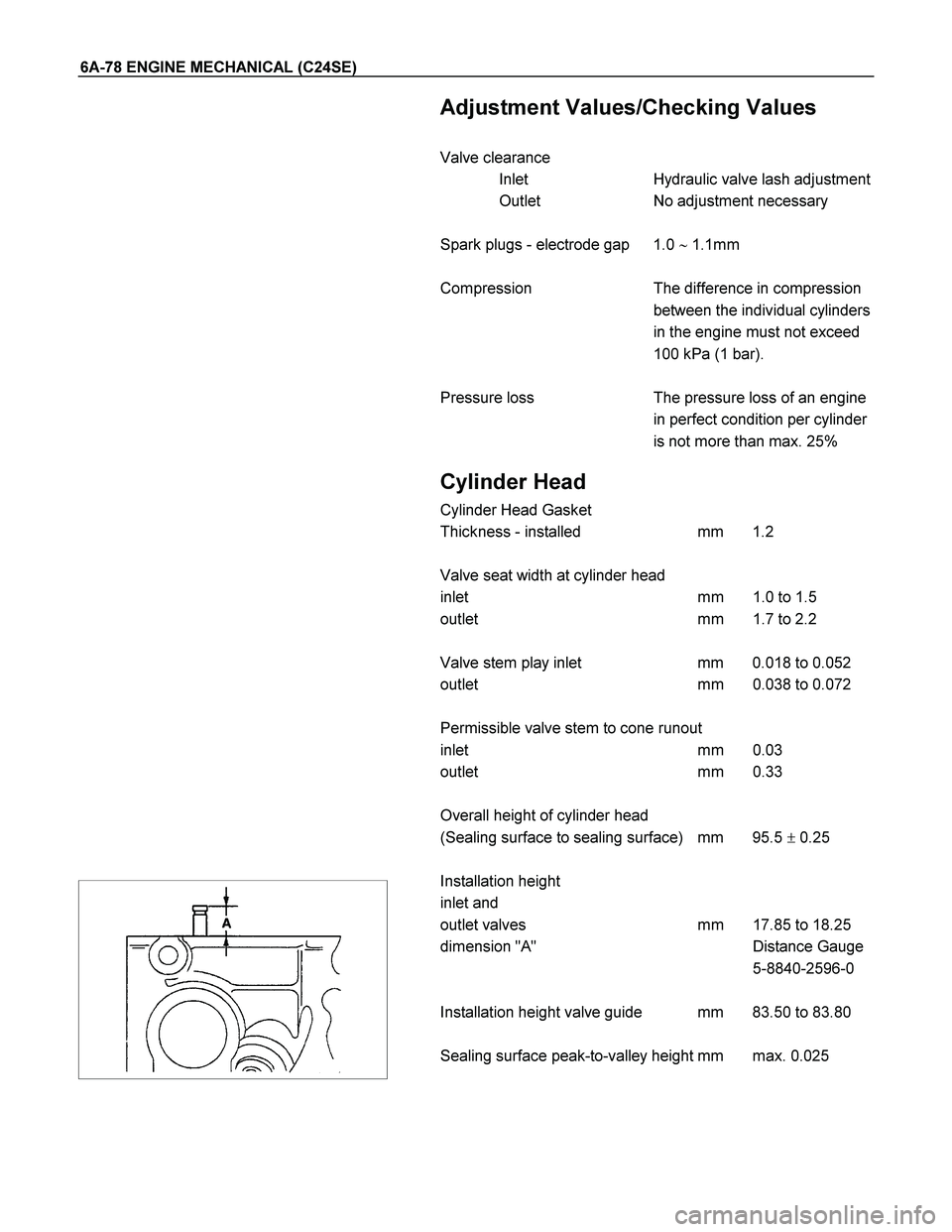
Installation height
inlet and
outlet valves mm 17.85 to 18.25
dimension "A" Distance Gauge
5-8840-2596-0
Installation height valve guide mm 83.50 to 83.80
Sealing surface peak-to-valley height mm max. 0.025
Page 2499 of 4264
 6A-79
Cylinder Head (continued)
Valve System
Valve lifter valve play compensator
(hydraulic)
Valve rotators
(inlet or outlet) outlet
Valve play
(warm or col")
ENGINE MECHANICAL (C24SE) 6A-79
Cylinder Head (continued)
Valve System
Valve lifter valve play compensator
(hydraulic)
Valve rotators
(inlet or outlet) outlet
Valve play
(warm or cold) inlet mm 0
outlet mm 0
Cylinder head height mm 280.3�0.075
Cylinder head bottom, face parallelism mm 0.05
Valve Dimensions
C24SE
A in mm B in
mm C(diameter in mm) and identification mark D
1) 2) Normal K Oversize K1
0.075 Oversize K2
0.150 Oversize A
0.250
Inlet valve 104.2 103.8 41.8 7.012
6.998 7.087
7.073 7.162
7.148 7.262
7.248 44�
Outlet valve 104.0 103.6 36.5 6.992
6.978 7.087
7.053 7.142
7.128 7.242
7.228 44�
Valve stem
bore - 7.050
7.030 7.125
7.105 7.200
7.180 7.300
7.280 -
1) Production
2) Customer service
The P and A department only supplies valves with a length of 103.8mm (inlet valve) and 103.6mm (outlet valve)
only
Camshaft
2.4L
Identification letter K
Colour code Normal size -
0.1mm undersize violet
Radial runout mm 0.03
End play mm 0.09 to 0.21
Cam lift Inlet and outlet valve mm 6.67
Page 2501 of 4264
 6A-81
Crankshaft, Cylinder Block
Cylinder Grinding and Piston Dimensions
Size Cylinder bore dia. in mm Cylinder to Related piston dia. in mm Piston head
Cranksh")
ENGINE MECHANICAL (C24SE) 6A-81
Crankshaft, Cylinder Block
Cylinder Grinding and Piston Dimensions
Size Cylinder bore dia. in mm Cylinder to Related piston dia. in mm Piston head
Crankshaft co- efficient
housing
co-efficient
over to over to
Production
(2.4L) 1 87.48
87.49 87.49
87.50 99
00 87.46
87.47 87.47
87.48 99
00
Customer
service
(2.4L) - 87.99 88.00 0+0.5 87.97 87.98 7+0.5
Piston diameter must be measured at the position "D".
*inclusive
Cylinder Bore
Rebore cylinder Permissible oversize to 0.5mm (see parts
microfiche)
After reboring, invalidate original crankcase
housing coefficient and drive in new oversize
coefficient
Permissible out-of-round: 0.013mm
Permissible taper: 0.013mm
Measure out-of-round in bore at 4 different
heights
Piston projection above upper edge of cylinder block
0.40mm
Piston
Type Recessed pistons
Clearance For short-blocks and cylinder blocks with
complete pistons, the clearance is 0.02 to
0.04mm
For replacement (oversize), depending on
available pistons, a clearance of 0.02 to
0.04mm is permissible
Page 2502 of 4264
6A-82 ENGINE MECHANICAL (C24SE)
Crankshaft, Cylinder Block (continued)
Piston Rings
2.4L
Square ring Height mm 1.2
Tapered ring Height mm 1.5
Oil scraper Height mm 2.5
Ring gap offset 180�
Note that the upper steel band ring gap is offset 25 to 50mm to
the left and the lower 25 to 50mm to the right opposite the
intermediate ring gap.
Piston Pin
Length mm 61.5
Diameter mm 21
Type Shrunk into con-rod
Play mm 2.4L
in piston 0.010-0.015
in con-rod none
Installation When installing piston pins,
heat con-rods to approx.
280�C in oil bath. This
temperature should under no
circumstances be exceeded.
Crankshaft, Cylinder Block (continued)
The permissible weight variation of con-rods without piston and
bearing shell inside an engine is 8 g.
As the con-rods do not have balancing studs, reworking is not
possible.
Con-rods can only be replaced in sets.
 6A-65
014RW060
2. Remove twenty fixing bolts from inlet and exhaust
camshaft bracket on one side bank, then camshaft
brackets (2).
014RW027
3. R")
 6A-39
Camshaft Housing, Check for Plane Surface
Clean
Sealing surfaces.
Inspection
Check length and width of sealing surface for deformation and
diagn")

Crankshaft, Cylinder Block (continued)
Piston Rings
2.4L
Square ring Height mm 1.2
Tapered ring Height mm 1.5
Oil scraper Height mm 2.5
Ring")