Page 3479 of 4264
POWER-ASSISTED STEERING SYSTEM 3B-49
Lock Cylinder
Lock Cylinder and Associated Parts
This illustration is based on the RHD model.
RTW43BLF000701
Legend
(1) Steering Column Cover
(2) Steering Wheel
(3) Inflator Module or Horn pad
(4) Combination Switch and SRS Coil Assembly
(5) Steering Column Assembly
(6) Lock Cylinder Assembly
(7) Instrument Panel Lower Cover
(8) Driver Knee Bolster (reinforcement)
Removal
1. Turn the steering wheel so that the vehicle's wheels
are pointing straight ahead.
2. Turn the ignition switch to "LOCK".
3. Disconnect the battery "-" terminal cable, and wait a
t
least 5 minutes. (with SRS air bag)
4. Disconnect the yellow 2-way SRS connector located
under the steering column. (with SRS air bag)
Page 3484 of 4264

Torque: 2 - 4 N�
�� �m (0.2 – 0.4 kg�
�� �m/")
3B-54 POWER-ASSISTED STEERING SYSTEM
10. Push the born pad area 1-4.
Tighten the born pad fixing screw to the specifed
torque (without SRS air bag)
Torque: 2 - 4 N�
�� �m (0.2 – 0.4 kg�
�� �m/17 - 35 lb ft)
NOTE: A horn pad is not struck at the time o
f
attachment.
RTW43BSH000401
11. Align the each snap stud of driver air bag to the hole
of steering wheel. (with SRS air bag)
060R300030
060R300020
12. Push the SRS air bag area1 and area2. At that time
confirm the audible noise of each stud. (with SRS ai
r
bag)
060R300036
13. Enable the SRS (Refer to "Enabling the SRS" in this
section). (with SRS air bag)
14. Install driver knee bolster (reinforcement).
15. Install instrument panel lower cover, then install the
engine hood opening lever.
16. Connect the yellow 2-way SRS connector located
under the steering column. (with SRS air bag)
17. Connect the battery "-" terminal cable. (with SRS ai
r
bag)
System Inspection (with SRS air bag)
Turn the ignition switch to "ON" while watching warning
light.
The light should flash 7 times and then go off. If lamp
does not operate correctly, refer to Restraints section.
Page 3485 of 4264
POWER-ASSISTED STEERING SYSTEM 3B-55
Steering Column
Steering Column and Associated Parts
This illustration is based on the RHD model.
RTW43BLF000201
Legend
(1) Inflator Module or Horn Pad
(2) Steering Wheel
(3) Steering Column Cover
(4) Combination Switch and SRS Coil Assembly
(5) Steering Column Assembly
(6) Second Steering Shaft
(7) Lower Second Steering Shaft
(8) Instrument Panel Lower Cover
(9) Driver Knee Bolster (reinforcement)
Removal
1. Turn the steering wheel so that the vehicle's wheels
are pointing straight ahead.
2. Turn the ignition switch to "LOCK".
3. Disconnect the battery "-" terminal cable, and wait at
least 5 minutes. (with SRS air bag)
4. Disconnect the yellow 2-way SRS connector located
under the steering column. (with SRS air bag)
Page 3490 of 4264

CAUTION: When turning the SRS coil counte
r")
3B-60 POWER-ASSISTED STEERING SYSTEM
9. Turn the SRS coil counter clockwise to full, return
about 3 turns and align the neutral mark. (with SRS
air bag)
CAUTION: When turning the SRS coil counte
r
clockwise to full, stop turning if resistance is felt.
Forced further turning may damage to the cable in
the SRS coil.
826RW014
10. When installing the steering column cover, be sure to
route each wire harness as illustrated so that the
harnesses do not catch any moving parts.
825RW017
Legend
(1) Steering Column Cover
(2) Starter Switch Harness
(3) Combination Switch Harness
(4) Inflator Module Harness
11. Install steering wheel and align the setting marks
made when removing.
Refer to the adjustment method in case a mark is
not attached in this section.
NOTE: Confirm SRS and Horn harness connector is
fixed by the steering wheel.
RTW33BSH000601
CAUTION: Never apply force to the steering wheel in
direction of the shaft by using a hammer or othe
r
impact tools in an attempt to remove the steering
wheel. The steering shaft is designed as an energy
absorbing unit.
12. Tighten the steering wheel fixing nut to the specified
torque.
Torque: 31 - 39 N�
�� �m (3.2 – 4.0 kg�
�� �m/23 - 29 lb ft)
13. Support the module and carefully connect the
module connector and horn lead, then install inflato
r
module.
NOTE: Pass the lead wire through the tabs on the
plastic cover (wire protector) of inflator to prevent lead
wire from being pinched.
14. Tighten bolts to specified torque.
Torque: 2 - 4 N�
�� �m (0.2 – 0.4 kg�
�� �m/17 - 35 lb in)
15. Install driver knee bolster (reinforcement).
16. Install instrument panel lower cover.
17. Install the engine hood opening lever.
18. Connect the yellow 2-way SRS connector and horn
lead located under the steering column.
19. Connect the battery "-" terminal cable. (with SRS ai
r
bag)
Page 3595 of 4264

TRANSFER CASE 7D-7
Removal
NOTE: Before removing transmission and transfer
assembly from vehicle, change the transfer mode to
2WD using the 4WD push button switch on dash panel.
1.
Disconnect battery ground cable.
2.
Raise and support vehicle with suitable stands. Drain
transfer case fluid.
3. Remove the center exhaust pipe(5). (6VE1 only)
4.
Remove rear propeller shaft (1) and front propelle
r
shaft (2)(3).
NOTE: Apply alignment marks on the flange at both
front and rear sides.
5.
Disconnect harness connectors and clip.
Connector: transfer switch, 2WD-4WD actuator,
speed sensor.
NOTE: Avoid turning the vehicle ignition switch to the
ON position when the 2WD-4WD connector is removed
(battery connected).
If the ignition switch must be turned to the ON position,
the controller must first be removed (memory must be
cleared because the CHECK 4WD INDICATOR will
light).
6.
Remove transfer case (4) from the vehicle.
Installation
1.
Apply a thin coat of molybdenum disulfide grease to
the input shaft spline as shown in the figure.
260R300001
Page 3598 of 4264
7D-10 TRANSFER CASE
Transfer Control Unit
RTW37DLF000401
Legend
(1) Transfer Control Unit
(3) Bolt
(2) Protector
Removal
1.
Disconnect the battery ground cable.
Remove the driver’s seat.
2.
Peel back the floor carpet on the driver's side of the
vehicle to expose the transfer control unit.
3.
Disconnect the harness connector from the Transfe
r
control unit.
4. Remove the Transfer control unit.
Installation
1.
Install the Transfer control unit.
2.
Connect the harness connector to the Transfe
r
control unit.
3.
Connect the battery ground cable.
Page 3658 of 4264
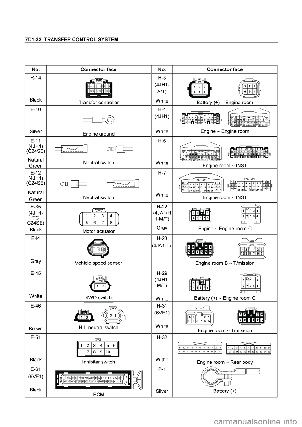
7D1-32 TRANSFER CONTROL SYSTEM
No. Connector face No. Connector face
R-14
Black
Transfer controller H-3
(4JH1-
A/T)
WhiteBattery (+) � Engine room
E-10
Silver
Engine ground H-4
(4JH1)
WhiteEngine � Engine room
E-11
(4JH1)
(C24SE)
Natural
Green
Neutral switch H-6
White
Engine room �
INST
E-12
(4JH1)
(C24SE)
Natural
Green
Neutral switch H-7
WhiteEngine room �
INST
E-35
(4JH1-
TC
C24SE)
Black
Motor actuator H-22
(4JA1/H
1-M/T)
Gray Engine �
Engine room C
E44
Gray
Vehicle speed sensor H-23
(4JA1-L)
Engine room B �
T/mission
E-45
White
4WD switch H-29
(4JH1-
M/T)
WhiteBattery (+) � Engine room C
E-46
Brown
H-L neutral switch H-31
(6VE1)
WhiteEngine room �
T/mission
E-51
Black
Inhibiter switch H-32
WitheEngine room � Rear body
E-61
(6VE1)
Black
ECM P-1
SilverBattery (+)
Page 3659 of 4264
TRANSFER CONTROL SYSTEM 7D1-33
No. Connector face No. Connector face
P-2
Silver
Relay & Fuse box
P-5
Silver
Battery (-)
P-6
Silver
Body earth (Ground)
P-10
Silver
Engine ground
P-13
(4JH1)
Gray
Shift on the fly actuator
R-14
Black 2-4WD Control unit
R-15
Black 2-4WD Control unit
 Steering Column Cover
(2) Steeri")
 Inflator Module or Horn")
 Transfer Control Unit
(3) Bolt
(2) Protector
Removal
1.
Disconnect the battery ground cable.
Remove the")

P-6
Silver
Body earth (Ground)
P-10
Silver
Engin")