Page 3113 of 4264
HEATER AND AIR CONDITIONING 1-103
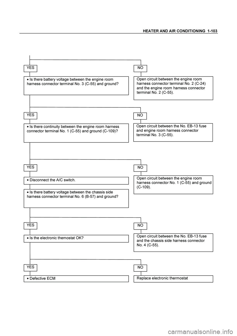
YES
�
Disconnect the A/C switch.
�
Is there battery voltage between the chassis side
harness connector terminal No. 6 (B-57) and ground?
Open circuit between the engine room
harness connector terminal No. 2 (C-24)
and the engine room harness connector
terminal No. 2 (C-55).
NO YES
�
Is there battery voltage between the engine room
harness connector terminal No. 3 (C-55) and ground?
Open circuit between the No. EB-13 fuse
and engine room harness connector
terminal No. 3 (C-55).
NO YES
�
Is there continuity between the engine room harness
connector terminal No. 1 (C-55) and ground (C-109)?
Open circuit between the engine room
harness connector No. 1 (C-55) and ground
(C-109).
NO
YES
�
Is the electronic themostat OK? Open circuit between the No. EB-13 fuse
and the chassis side harness connector
No. 4 (C-55).
NO
YES
�
Defective ECM Replace electronic thermostat
NO
Page 3125 of 4264

MSG MODEL 7B-7
REMOVAL AND INSTALLATION
Read this Section carefully before performing any removal and installation procedure. This Section gives you
important points as well as the order of operation. Be sure that you understand everything in this Section before
you begin.
Important Operations - Removal
Battery Cable
Disconnect the negative (-) cable from the battery terminal.
Engine Hood
Apply setting marks to the engine hood and the engine hood
hinges before removing the engine hood.
Gear Shift Lever
1. Place the gear shift lever in the neutral position.
2. Remove the gear shift lever knob.
3. Remove the front console assembly.
4. Remove the gear shift lever grommet and dust cover.
5. Remove the gear shift lever cover bolts.
6. Remove the gear shift lever.
Note:
Cover the shift lever hole to prevent the entry of foreign
material into the transmission.
Lifting the Vehicle
1. Jack up the vehicle.
2. Place chassis stands at the front and the rear of the
vehicle.
Transmission Oil Draining
1. Remove the transmission oil drain plug.
2. Replace the drain plug after draining the oil.
Page 3132 of 4264
7B-14 MSG MODEL
Exhaust Pipe
1. Install the exhaust pipe to the exhaust manifold and the
2nd exhaust pipe.
2. Install the exhaust pipe bracket to the transmission case.
Gear Shift Lever
1. Replenish the transmission case with the specified engine
oil.
Transmission Case Oil lit(US gal.)
1.55 (0.41)
2. Install the gear shift lever to the gear control box.
3. Tighten the gear shift lever cover bolts to the specified
torque.
Shift Lever Cover Bolt Torque N�
m(kgf�
m/lb�
ft)
19.6 (2.0 / 14.5)
4. Install the dust cover and the grommet.
5. Install the front console assembly.
6. Install the gear shift lever knob.
Lowering the Vehicle
1. Place a jack beneath the vehicle.
2. Raise the jack to remove the chassis stands.
3. Lower the vehicle to the ground.
Engine Hood
Align the setting marks(applied at removal)on the engine hood
and the engine hood hinges to install the engine hood.
Battery Cable
Connect the negative (-) cable to the battery terminal.
Page 3172 of 4264
7B1-8 MANUAL TRANSMISSION
Removal
1. Disconnect battery ground cable.
2. Remove gear control lever knob (1).
3. Remove rear floor console (2). (Bucket seat)
Refer to the section “Floor Console”.
4. Remove front floor console (3).
Refer to the section “Floor Console”.
745R300006
Legend
(1) Knob
(2) Rear Floor Console
(3) Front Floor Console
5. Remove grommet assembly (4).
RTW47BMH000101
Page 3181 of 4264
. (6VE1)
Torque: 67 N�
�� �m (6.8 kg�
�� �m/49 lb�
�� �ft)
RTW37ASH000101
15. Install rear propeller shaft (6).
Torque: 63 N�
�� �")
MANUAL TRANSMISSION 7B1-17
14. Install the exhaust pipe (8). (6VE1)
Torque: 67 N�
�� �m (6.8 kg�
�� �m/49 lb�
�� �ft)
RTW37ASH000101
15. Install rear propeller shaft (6).
Torque: 63 N�
�� �m (6.4 kg�
�� �m/46 lb�
�� �ft)
16. Install center bearing on crossemember.
Torque: 69 N�
�� �m (7.0 kg�
�� �m/51 lb�
�� �ft)
17. Install gear control lever (5).
Torque: 19 N�
�� �m (1.9 kg�
�� �m/14 lb�
�� �ft)
18. Install grommet assembly (4).
Torque: Screw 1.4 N�
�� �m (0.14 kg�
�� �m/12 lb�
�� �in)
Nut 7 N�
�� �m (0.7 kg�
�� �m/61 lb�
�� �in)
RTW47BMH000101
Legend
(1) Grommet Assembly
(2) Floor Panel
(3) Front
19. Install front floor console (3) and rear floor console
(2).
20. Install gear control lever knob (1).
To the female thread portion, adhesive (TB1344 or
LOCTITE 222 or equiv.) of 3 - 4 drops to be applied
and transmission knob tightened.
Torque: 9 N�
�� �m (0.9 kg�
�� �m/78 lb�
�� �in)
After tightening to specified torque, knob
rewrenched until direction of shift pattern due
positioned.
21. Connect battery ground cable.
Page 3229 of 4264
MANUAL TRANSMISSION 7B1-65
Removal
1. Disconnect battery ground cable.
2. Remove gear control lever knob (1).
3. Remove rear floor console (2). (Bucket seat)
Refer to the section “Floor Console”.
4. Remove front floor console (3).
Refer to the section “Floor Console”.
745R300006
Legend
(1) Knob
(2) Rear Floor Console
(3) Front Floor Console
5. Remove grommet assembly (4).
RTW47BMH000101
Page 3239 of 4264
MANUAL TRANSMISSION 7B1-75
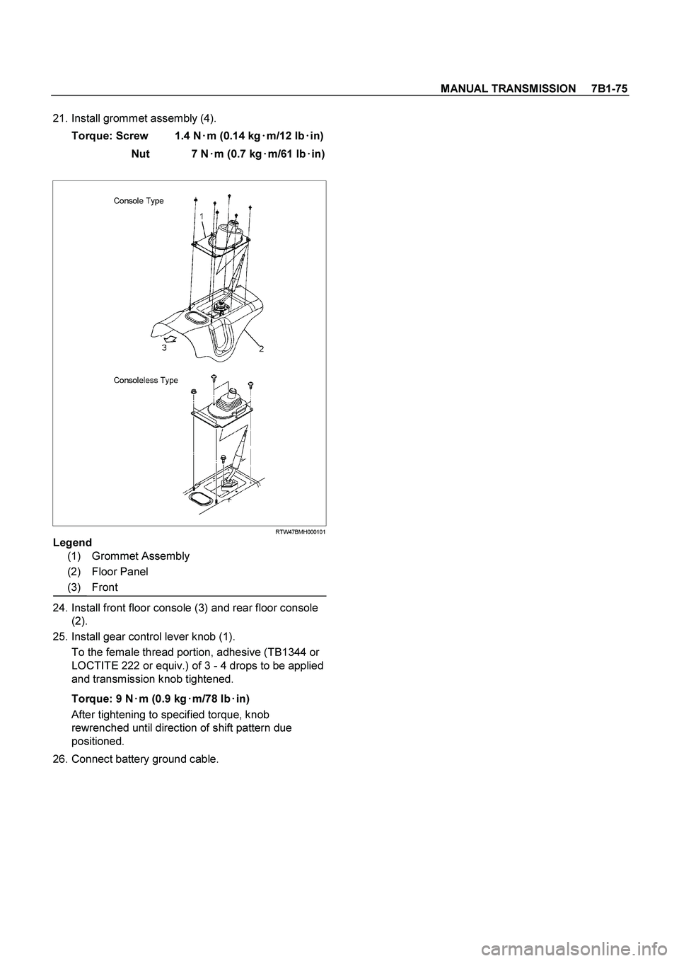
21. Install grommet assembly (4).
Torque: Screw 1.4 N�
�� �m (0.14 kg�
�� �m/12 lb�
�� �in)
Nut 7 N�
�� �m (0.7 kg�
�� �m/61 lb�
�� �in)
RTW47BMH000101
Legend
(1) Grommet Assembly
(2) Floor Panel
(3) Front
24. Install front floor console (3) and rear floor console
(2).
25. Install gear control lever knob (1).
To the female thread portion, adhesive (TB1344 or
LOCTITE 222 or equiv.) of 3 - 4 drops to be applied
and transmission knob tightened.
Torque: 9 N�
�� �m (0.9 kg�
�� �m/78 lb�
�� �in)
After tightening to specified torque, knob
rewrenched until direction of shift pattern due
positioned.
26. Connect battery ground cable.
Page 3317 of 4264

IMMOBILIZER SYSTEM 11A-31
Diagnostic procedure
�
Once the cause of DTC is repaired or gone,
engine can be operated normally, and present
DTC becomes history code.
�
History code is canceled by no repeat failure on 25
consequence ignition key on afterward.
�
History code cannot be canceled by batter
y
connector disconnected.
Clearing Diagnostic Trouble Codes
IMPORTANT:
Do not clear DTCs unless directed to do
so by the service information provided for each
diagnostic procedure. When DTCs are cleared, the
Failure Record data which may help diagnose an
intermittent fault will also be erased from memory.
Verifying Vehicle Repair
Verification of vehicle repair will be more
comprehensive for vehicles with immobilizer system
diagnostic. Following a repair, the technician should
perform the following steps:
1.
Review and record the Fail Records for the DTC
which has been diagnosed.
2.
Clear DTC(s).
3.
Operate the vehicle within conditions noted in the
Fail Records.
4.
Monitor the DTC status information for the DTC
which has been diagnosed until the diagnostic test
associated with that DTC runs.
Following these steps are very important in verifying
repairs on immobilizer systems. Failure to follow these
steps could result in unnecessary repairs.
Diagnostic Aids
Check the condition for system parts.
�
Installation condition, poor connection, damage,
system parts malfunction. Harness, Fuse, Relay,
Immobilizer coil (antenna), Key, Meter, Immobilize
r
control unit (ICU), Engine control module (ECM).
NOE: Breakage of immobilizer fuse does not operate
immobilizer system. Check engine lamp flashes at this
time.
Check the Electro-Magnetic Interference (EMI)
�
Location of vehicle check
Move the vehicle to a new location and perform
the check again.
�
Non-OEM Parts.
Switch is "OFF" or remove the Non-OEM parts and
perform the check again.
�
Other
Remove the accessory and another key from key.
Check the other items.
�
Battery voltage is low.
�
Immobilizer programming functions.
Must be programmed immobilizer system.
�
Registration for security code, immobilizer control
unit parts number.
�
Key switch operation.
Immobilizer system may detect a history DTC b
y
the timing of ON-OFF of a key switch.
�
Active the immobilizer system.
�
Keyless entry system is malfunction.
�
Anti theft system is malfunction.
Check the operation
Check the operation "Lock / unlock" by using transmitte
r
(key) on the vehicle.

.
3. Remove rear floor console (2). (Bucket seat)
Refer to the section “Flo")
.
3. Remove rear floor console (2). (Bucket seat)
Refer to the section “Fl")